Pepwave AP One Series: AP One/ AP One 300M / AP One mini / AP One Flex / AP One In-Wall Pepwave AP Pro Series: AP Pro Document Rev.3.0.10 Mar 27, 14 COPYRIGHT & TRADEMARKS Specifications are subject to change without notice. Copyright © 3/27/14 Pepwave Ltd. All Rights Reserved. Pepwave and the Pepwave logo are trademarks of Pepwave Ltd. Other brands or products mentioned may be trademarks or registered trademarks of their respective owners.
User Manual Table of Contents 1. Introduction and Scope .....................................................................................................4 2. Product Features and Benefits .........................................................................................5 3. Package Contents ...........................................................................................................6 3.1 AP One ...................................................................................
User Manual 9. Commands .......................................................................................................................64 9.1 Activate Changes .........................................................................................................65 9.2 Firmware .......................................................................................................................66 9.3 Configuration ..................................................................................
User Manual 1. Introduction and Scope Pepwave’s AP Series of enterprise-grade 802.11b/g/n Wi-Fi access points is engineered to provide fast, dependable, and flexible operation in a variety of environments, all controlled by an easy-to-use centralized management system.
User Manual 2. Product Features and Benefits Key features and benefits of the Pepwave AP series: High-powered Wi-Fi transmitter enhances coverage and lowers cost of ownership. Independent security policies and encryption mechanisms for each virtual access point allow fast, flexible, cost-effective network builds. Centralized management via InControl reduces maintenance expense and time. WDS support allows secure and fast network expansion.
User Manual 3. Package Contents 3.1 AP One Each Pepwave AP One package contains: 1 x Pepwave AP One 1 x omni-directional antenna 1 x power supply 1 x instruction sheet 3.2 AP One 300M Each Pepwave AP One 300M package contains: 1 x Pepwave AP One 300M 2 x omni-directional antennas 1 x power supply 1 x instruction sheet 3.3 AP One mini Each Pepwave AP One mini package contains: 1 x Pepwave AP One mini 1 x omni-directional antenna 1 x power supply 1 x instruction sheet 3.
User Manual 3.5 Ap One In-Wall Each Pepwave AP One In-Wall package contains: 1 x Pepwave AP One In-Wall 1 x mounting kit 3.6 AP Pro Each Pepwave AP Pro package contains: 1 x Pepwave AP Pro 1 x instruction sheet 1 x installation guide http://www.pepwave.
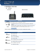
User Manual 4. Hardware Overview 4.1 AP One Front View Rear Panel View Connectors Antenna RP-SMA connector for attaching the antenna. (Left Connector) WAN Reset 10/100BaseT Ethernet connector, normally connected to a back haul network. Inset reset button. Depress with a pin and hold for at least five seconds to restore factory defaults. For further details, please refer to Restoring Factory Defaults. Power Connector DC 12V power input for use with the supplied power adapter.
User Manual 4.2 AP One 300M Front View Rear Panel View Connectors USB WAN Reserved for future functionality. 10/100BaseT Ethernet connector, normally connected to a back haul network. 10/100BaseT Power over Ethernet 802.3af connector, normally connected to a back haul network. WAN Inset reset button. Depress with a pin and hold for at least five seconds to restore factory defaults. For further details, please refer to Restoring Factory Defaults.
User Manual 4.3 AP One mini Front View Rear Panel View Connectors USB Reserved for future functionality. Power Connector DC 12V power input for use with the supplied power adapter. 10/100BaseT Ethernet connector, normally connected to a back haul WAN network. Antenna RP-SMA connector for attaching the antenna. (Right Connector) LED Indicators PWR OFF – Power is off. ON – Power is on. RDY RED – Device is not booted. AMBER – Device is not booted. ENET OFF – Ethernet port is not connected.
User Manual 4.4 AP One Flex Front View Rear LED Indicators Connectors Panel inside the lid Connectors LAN1*PoE LAN2 / 3 Reset 10/100BaseT Power over Ethernet Passive PoE connector Ethernet LAN Port Inset reset button. Depress with a pin and hold for at least five seconds to restore factory defaults. For further details, please refer to Restoring Factory Defaults. http://www.pepwave.
User Manual LED Indicators OFF – Unit is initializing. ON – Unit is ready. OFF – Ethernet port is not connected. LAN ON – Ethernet port is connected. Indicate the signal strength. Mounting the Unit Pepwave AP One Flex can be mounted on a flat surface or a pole using the wall/pole mount (available separately). Flexible ball joint to connect to AP One Flex Pole/Wall Mount Pole/Wall Mount with Ball Joint Pole/Wall Mount For pole mount with metallic strips http://www.pepwave.
User Manual 4.5 AP One In-Wall Front View Top View Connectors Panel at the bottom Connectors Panel at the side Connectors LAN POE IN LAN/UPLINK Reset Pass Through Ethernet LAN ports 10/100BaseT Power over Ethernet Passive PoE connector Inset reset button. Depress with a pin and hold for at least five seconds to restore factory defaults. For further details, please refer to Restoring Factory Defaults. Digital pass through for PBX Power Connector DC 48V power input. http://www.pepwave.
User Manual 4.6 AP Pro Front View Top View AP Pro Rear Panel View AP Pro 300M Rear Panel View AP Pro Duo Rear Panel View Connectors Antenna Female N-type connectors for attaching antennas. Ground Ground connection. Console RJ-45 Console connector for Pepwave Console Adapter with remote factory reset functionality. WAN Power Connector 10/100BaseT Power over Ethernet 802.3af connector, normally connected to a back haul network.
User Manual 5. Installation Your Pepwave access point acts as a bridge between wireless and wired Ethernet interfaces. A typical setup follows: http://www.pepwave.
User Manual 5.1 Installation Procedures 1. Attach the antenna to your Pepwave access point. 2. Connect the Ethernet port on the unit with the backbone network using an Ethernet cable. The port should auto sense whether the cable is straight-through or crossover. 3. Connect the power adapter to the power connector of the unit. Plug the power adapter into a power source. 4. Wait for the status LED to turn green. 5. Connect a PC to the backbone network.
User Manual 6. Information The Information section contains a number of tabs to keep you up-to-date on your access point’s status and operation. http://www.pepwave.
User Manual 6.1 System Click System, located under Information on the left, to display tabs for basic and advanced AP configuration options. System Information Model Firmware Version Model name of your access point. Firmware version number running on your access point. AP Name Name of your access point as defined in the configuration. Location Location of your access point as defined in the configuration. Serial Number Serial number of your access point.
User Manual Click Close to dismiss the IP Info dialog. Wireless Click Wireless, located under Information on the left, to display tabs containing information about your Pepwave access point, connected clients, WDS, and nearby networks. http://www.pepwave.
User Manual 6.1.1 AP Info http://www.pepwave.
User Manual Wireless Information – AP Info Wireless Network SSID Radio Security Policy Channel Default VLAN ID MAC Address (BSSID) SSID of your access point. Frequency used by your access point’s radio. Wireless authentication and encryption methods used by your access point. 802.11 channel used by your access point. VLAN ID tagged onto all outgoing packets generated using the current wireless network profile. Detailed BSSIDs for the current wireless network profile.
User Manual 6.1.2 Connected Clients Wireless Information – Connected Clients Refresh Interval Refresh Total Interval used when refreshing connected client data. Click to manually refresh connected client data. Number of connected clients since the last refresh. MAC address Client MAC address. Manufacturer AP manufacturer name, based on MAC prefix. IP Address IP address of the connected client. Type Radio mode of the connected client. Signal Duration Signal strength of the connected client.
User Manual 6.1.3 WDS Info Wireless Information – WDS Info Local MAC Address MAC address identifying the local system. Current Channel Current 802.11 broadcast channel used by the system. Manufacturer Access point manufacturer name, based on MAC prefix. MAC Address MAC address for connected peers. Status Encryption Current WDS status: enabled or disabled. Encryption method used by the WDS. Click Edit to enable or disable WDS, edit the WDS MAC address, and select an encryption method. http://www.
User Manual 6.1.4 Nearby Networks Wireless Information – Nearby Networks Displays whether your access point is set to scan and discover nearby Network Discovery access points. How often your access point scans for nearby access points, providing Scanning Interval Network Discovery is Enabled.
User Manual 7. Configuration The Configure section allows you to set up all aspects of your Pepwave access point, from basic system settings to advanced wireless options and more. http://www.pepwave.
User Manual 7.1 System Click System, located under Configure on the left, to display tabs for basic and advanced AP configuration options. 7.1.1 Basic System Settings - Basic AP Name User-specified name assigned to your Pepwave access point. This name can be retrieved via SNMP. Location User-specified name for the location of your access point. This name can be retrieved via SNMP. Timezone Time region used by the system. All choices are based on UTC.
User Manual IP Address Mode – Manual Unique IP address used by your Pepwave access point to communicate Static IP Address on the Ethernet segment. This IP address is distinct from the admin IP address (192.168.0.3) on the Ethernet segment. Subnet Mask Default Gateway DNS Server Subnet mask used by your access point. Default gateway used by your access point. DNS server address used by your Pepwave access point to resolve host names.
User Manual 7.1.2 Advanced System Settings - Advanced VLAN ID from which management sessions are allowed. Establishment of management sessions is restricted to the specified VLAN ID. If Management VLAN Management VLAN ID is set to 0, management sessions can be ID established without VLAN ID restrictions. Default value is 0, which means that tagging is disabled, not that management sessions will be tagged with 0.
User Manual 7.1.2.1 Manual Router Settings Manual Router Settings are available only when AP Mode in Advanced System Settings is set to Router. When using Router mode, your Pepwave access point can be used as a DHCP server for devices located behind it in the network. Manual Router/DHCP Server Parameters LAN IP DHCP server IP address. LAN Subnet Mask Subnet mask of the DHCP server. DHCP Server Check to enable the DHCP server feature of your Pepwave access point.
User Manual Lease Time Length of time that an IP address of a DHCP client remains valid. When lease time has expired, the assigned IP address is no longer valid, and renewal of the IP address assignment is required. http://www.pepwave.
User Manual 7.2 LAN Select LAN, located under Configure on the left, to begin configuring a local area network for your Pepwave access point. 7.2.1 LAN http://www.pepwave.
User Manual LAN LAN IP IP address of your Pepwave access point. LAN Subnet Mask Specifies the number of clients that can connect to your access point. DHCP Server Check to enable the DHCP server feature of your access point. Enabling DHCP is the best option for most users. The following options will be enabled once you have checked and enabled DHCP Server. IP Start Range First address in the range of IP addresses assigned to DHCP clients. Default is 192.168.1.
User Manual 7.2.2 DMZ DMZ DMZ DMZ IP Enable your AP One unit to become a DMZ device. Address used by external users to connect to your IP’s ports. 7.2.3 Port Forward Port Forward Name IP Port Name for your port forwarding rule. IP address to which ports are forwarded. Choose TCP or UDP to forward the selected port or port range using the specified protocol. Select port options from the drop-down menus on the right, then click Apply to make the port forwarding rule active. http://www.pepwave.
User Manual 7.3 Wireless Networks Select Wireless Networks, located in the Configure section on the left, to display your Pepwave access point’s SSID configuration. General Wireless Network Settings Wireless Network SSID of the virtual access point. SSID Wireless authentication and encryption used by your Pepwave access Security Policy point. Default VLAN ID Status MAC Address (BSSID) VLAN ID tagged on all outgoing packets generated by the virtual AP (i.e.
User Manual Click Info to check Broadcast SSID, Web Portal Login, MAC Filter, Bandwidth Control, and Layer 2 Isolation. General Wireless Networks Settings – Info Broadcast SSID Displays whether or not your Pepwave access point’s SSID is broadcast. Displays whether or not your access point can be accessed via Web Web Portal Login portal. MAC Filter Displays whether or not your access point controls access with MAC address filters.
User Manual To add a new virtual AP, click the Add button. To change network details for a virtual AP, click its Edit link, which give you access to Wireless Network Details, explained on the next page. http://www.pepwave.
User Manual 7.3.1 Wireless Network Details - Basic Wireless Network Details - Basic Enable Select Yes to enable the virtual AP. Select No to disable. The virtual AP is enabled by default. Wireless Network SSID of the virtual AP as it appears to Wi-Fi clients. SSID Check Enable to allow Wi-Fi clients to scan the virtual AP’s ESSID. Note that the BSSID (i.e., the MAC address of the virtual AP) cannot be hidden Broadcast SSID from the scan.
User Manual 7.3.1.1 Static WEP Parameters The configuration of Static WEP parameters enables pre-shared WEP key encryption. Please note that static WEP offers weak security and does not support authentication. Static WEP Parameters Key Size Choose 40 bits (64-bit WEP) or 104 bits (128-bit WEP). When using the WDS setting, 128 bits will also be available. Key Format Choose ASCII or HEX.ASCII can be applied only to encryption keys that are manually entered.
User Manual 7.3.1.2 802.1X Parameters The configuration of 802.1X parameters enables RADIUS-based 802.1X authentication with a dynamic WEP key. 802.1x Parameters 802.1X Version Choose v1 or v2 of the 802.1x EAPOL. When v1 is selected, both v1 and v2 clients can associate with the access point. When v2 is selected, only v2 clients can associate with the access point. Most modern wireless clients support v2. For stations that do not support v2, select v1. Default is v2.
User Manual 7.3.3.3 WPA parameters The configuration of WPA parameters enables WPA-TKIP, WPA2-AES:CCMP, and WPA-TKIP and WPA2-AES:CCMP. To enable WPA and WPA-PSK, configure WPA-TKIP. To enable WPA2 and WPA2-PSK, configure WPA2-AES. When WPA or WPA2 is configured, RADIUSbased 802.1x authentication with TKIP encryption method is enabled. When using this configuration, Pre-Shared Key should be disabled. The security level of this method is known to be very high.
User Manual 7.3.4 Web Portal Login Once your Pepwave access point is registered with Pepwave InControl, you can apply configurations, update firmware, and monitor network activity remotely using this centralized management system. For details, see http://www.pepwave.com/products/incontrol/. 7.3.4.1 Tip: How to Set Up a Pepwave AP Guest Portal in InControl To set up a Guest Portal, (1) enable the guest portal function and (2) create guest accounts and set up a portal page.
User Manual 3. To find your wireless network, click the Wireless tab. Next, check Wireless Networks, then click More…. 4. Click the name of the SSID you have set up. Note: If you have not added a wireless network, click New wireless network... to create one. 5. On the Edit a wireless network page, click the Web Portal Login tab. Click Enable to enable Web portal logins. Click OK to continue. 6. Click Save to save your changes. 7.
User Manual 7.3.5 Guest Protect http://www.pepwave.
User Manual Wireless Network Details - Guest Protect Enables settings to Block all private IPs / Custom Subnet / Block Exception. If you have selected Block all private IPs or Custom Subnet, these IPs / subnets will be blocked no matter what Firewall Mode is selected. When Block Exception is selected, IPs entered will be excluded from the blocking list. Block LAN Access Block SpeedFusion™ Bandwidth Management Upstream Limit Private IP – Blocks common private IPs: o 192.168.0.0 – 192.168.255.
User Manual 7.3.6 MAC Filter These settings allow your administrator to control access using Mac address filtering. Choose from None, Deny all except listed, Accept all except listed, and RADIUS MAC Authentication. To delete MAC addresses from the list, select them, then click Delete highlighted. To add MAC addresses to the list, select them, then click <<
User Manual 7.3.7 Advanced http://www.pepwave.
User Manual Wireless Network Details - Advanced Data Rate Choose Fixed or Auto. Fixed forces all data packets to be transmitted using the selected transmit rate. Auto selects the best transmit rate, using the selected transmit rate as the minimum auto transmit rate. The rate options and values chosen here will be affected by selected Protocol and Channel Bonding. Multicast Filter Enables filtering multicast network traffic to the wireless SSID.
User Manual 7.3.8 RADIUS Server RADIUS Server Settings Primary Host Secret When 802.1x authentication is configured, the RADIUS server specified by this setting will be used for authentication and accounting. Shared secret password for accessing the RADIUS server. Authentication Port UDP port number for the authentication port of the RADIUS server. Accounting Port UDP port number for the accounting port of the RADIUS server.
User Manual 7.4 Advanced Wireless Settings Advanced Wireless Settings provides more options to fine-tune system parameters for optimal performance. http://www.pepwave.
User Manual 7.4.1 Radio Settings Advanced Wireless Settings - Radio Settings 802.11bgn: Pepwave access point accepts 802.11b, 802.11g, and 802.11n client association requests. 802.11b/g: Pepwave access point accepts both 802.11b and 802.11g client association requests. Protocol 802.11b Only: Pepwave access point accepts only 802.11b client association requests. 802.11g Only: Pepwave access point accepts only 802.11g client association requests. 802.11n Only: Pepwave access point accepts only 802.
User Manual 7.4.2 Advanced Features Advanced Wireless Settings – Advanced Features Discover Nearby Networks Enables your Pepwave access point to scan and discover nearby networks. Specifies how often your access point goes to other channels to discover Scanning Interval nearby networks. Scanning Time Specifies how long your access point stays on other channels to discover nearby networks. Scheduled Radio Availability Click Add to specify radio availability schedule options.
User Manual 7.4.3 Performance Tuning Advanced Wireless Settings – Performance Tuning Beacon Rate Choose 1Mbps, 2Mbps, 5.5Mbps, 6Mbps, or 11Mbps beacon rate. Default is 6Mbps when using a 5Ghz radio. Beacon Interval Time between each beacon transmission: 100ms, 250ms, or 500ms. DTIM RTS Threshold Frequency for beacon to include Delivery Traffic Indication Message (DTIM) in milliseconds. Minimum packet size needed to send an RTS using the RTS/CTS handshake. A setting of 0 disables this feature.
User Manual 7.5 WDS Wireless Distributed System, or WDS, provides a way to link APs when wired cabling is not preferable. WDS also extends wireless network coverage for wireless clients. Click Add to add and configure a new WDS peer connection. WDS Settings Enable MAC Address Encryption Enables WDS. MAC address of the other AP with which to form a WDS link. Security policy used for WDS peer connections. http://www.pepwave.
User Manual 7.6 SpeedFusion™ Select SpeedFusion™, located under Configure on the left, to begin configuring SpeedFusion connection parameters. SpeedFusion™ - SpeedFusion™ Local ID Name Local ID to be recognized by peers. Name representing this profile. The name can be any combination of alphanumeric characters (0-9, A-Z, a-z), underscore (_), dash (-), and/or non-leading/trailing spaces ( ). Remote peer serial number.
User Manual 7.6.1 SpeedFusion™ Settings Click Add to add a new SpeedFusion connection. http://www.pepwave.
User Manual SpeedFusion™ - SpeedFusion™ Settings Enable Select Yes to enable this SpeedFusion profile. Name Name representing this profile. The name can be any combination of alphanumeric characters (0-9, A-Z, a-z), underscore (_), dash (-), and/or non-leading/trailing spaces ( ). Encryption Select 256-bit AES to enable encryption or select Off to disable it. Remote ID Name representing the remote peer. The VPN profile will established only if the remote unit’s ID or serial number matches Remote ID.
User Manual IP Address Mode IP Address Subnet Mask Data Port IP Address Mode options are Automatic and Manual. Automatic: The IP address of your access point is acquired from a DHCP server on the Ethernet segment. Manual: A user-specified IP address is used for your access point. User-specified IP address for use with Manual IP Address Mode, above. Subnet mask used by your access point. This field specifies the outgoing UDP port number for transporting VPN data.
User Manual 7.7 SNMP 7.7.1 SNMP Settings Select SNMP, located under Configure on the left, to begin configuring SNMP server settings. SNMP - SNMP Settings Server Name Name identifying the SNMP server. SNMPv1 Enable support for Version 1 of SNMP. SNMPv2 Enable support for Version 2 of SNMP. SNMPv3 Enable support for Version 3 of SNMP. SNMP Trap Enable SNMP trap messaging, which is initiated by a client and sent to your Pepwave access point. http://www.pepwave.
User Manual 7.7.2 SNMPv1 / SNMPv2 Communities Using SNMPv1/v2 communities, access rights can be controlled. Click New to add a new SNMP v1/v2 community, or click Edit to change the settings of an existing community. Click Remove to delete a community. SNMPv1 / SNMPv2 Community - Settings Community Name Password for getting or setting SNMP values. IP Address and IP IP and subnet address that is allowed to access the SNMP server. Mask Choose Read Only or Read & Write.
User Manual 7.7.3 SNMPv3 Users By adding SNMPv3 users, access rights can be controlled. Click New to add a new SNMPv3 user, or click Edit to change the settings of an existing user. Click Remove to delete an SNMPv3 user. http://www.pepwave.
User Manual SNMPv3 User - Settings SNMPv3 User Name User ID allowed to access the SNMP agent. Authentication Protocol Protocol for authenticating the user. Choose HMAC-MD5 or HMAC-SHA. Authentication Password Users provided with a correct password will be granted the right to access the SNMP agent. Privacy Protocol Encryption method to be used in SNMPv3 communication. Choose None or CBC-DES. Shown only if CBC-DES is chosen as the Privacy Protocol.
User Manual 7.8.2 Admin Username Admin Username configures the administrator username used to access the Web Admin Interface. To change the administrator username, enter a new username in New Admin Username. 7.8.3 Admin Password Admin Password configures the administrator password used to access the Web Admin Interface. To change to the administrator password, enter the new password into New Password and New Password (confirmation). Note that the two entries must match exactly. 7.8.
User Manual 8. Tools - Diagnostic Tools This selection provides three useful tools for diagnosing problems on your network: Ping, Traceroute, and Nslookup. http://www.pepwave.
User Manual 9. Commands Commands, located on the left side of the Main Menu, puts a number of system control commands at your fingertips. http://www.pepwave.
User Manual 9.1 Activate Changes Click Activate Changes, located under Commands on the left, and confirm to save your configuration and activate your Pepwave access point. http://www.pepwave.
User Manual 9.2 Firmware Click Firmware, located under Commands on the left, to check firmware versions, select a boot ROM, and update your Pepwave access point’s firmware. Commands – Upgrade Firmware Firmware Version The firmware version loaded into the flash partitions. Flash Status Boot from The firmware status on the flash partitions. Indicates which flash partition boots up the system. Firmware Upgrade Indicates which flash partition will be upgraded with the next firmware upgrade.
User Manual 9.3 Configuration Click Configuration, located under Commands on the left side of the main menu, to restore factory default settings, backup configurations, and restore backed up configurations. Commands - Configuration Restore Factory Default Used to restore your Pepwave access point’s factory default settings. Preserve the network settings by checking Preserve Settings, then click Proceed.
User Manual 9.4 Misc Commands - Misc Download Debug Information Download debugging information from your Pepwave access point. To facilitate prompt resolution by Pepwave technical support in the event of technical issues, please send a debug file with your support request. Remote Assistance Get remote assistance with technical issues. Reboot your Pepwave access point using firmware saved in Flash 1 or Flash 2. Reboot AP http://www.pepwave.
User Manual 10. Real Time Status Real Time Status displays the current status of your Pepwave acess point device. If your access point is managed by a Peplink Balance, the default access of the Balance will be shown. http://www.pepwave.
User Manual 11. Peplink Balance AP Controller Since firmware 3.0.6, Pepwave access points can be managed and configured using a Peplink Balance. For details, including the Captive Portal configuration or how Peplink Balance works as an AP Controller, please refer to the Peplink website, FAQs, and Peplink Balance User Manual. http://www.pepwave.
User Manual 12. Restoring Factory Defaults The following procedure restores the settings of your Pepwave to factory defaults: Power on the unit and wait for one minute. Press and hold the reset button for at least five seconds, then release. The unit will automatically reboot. Wait for one minute or until the Status LED turns green, upon which the settings of the device will have been restored to the factory defaults. By default, the unit will acquire an IP address from a DHCP server. 12.1 AP One 12.
User Manual 12.3 AP One Mini 12.4 AP One Flex 12.5 AP One In-Wall http://www.pepwave.
User Manual 12.6 AP Pro You can restore AP Pro via the Console Adapter. http://www.pepwave.
User Manual 13. Appendix Federal Communication Commission Interference Statement This equipment has been tested and found to comply with the limits for a Class A digital device, pursuant to Part 15 of the FCC Rules. These limits are designed to provide reasonable protection against harmful interference in a residential installation.
www.pepwave.com Contact Us: Sales http://www.pepwave.com/contact/sales/ Support Address: United States Office 800 West El Camino Real, http://www.pepwave.com/contact/ Mountain View Business Development and Partnerships CA 94040 United States Tel: +1 (650) 331 0641 Fax: +1 (650) 625 4664 http://www.pepwave.