Model #: ___________________________ Serial #: ___________________________ Date Purchased: ____________________ Installation & Operation Manual PG14D: Floor Model Gas Pasta Cooker RS14D: Floor Model Rinse Station Built after 4/1995 C E E S I G N D D CERT I F I ED E R T I F I L20-294, R1.
TO THE PURCHASER, OWNER AND STORE MANAGER Please review these warnings prior to posting them in a prominent location for reference. TO THE PURCHASER WARNING Post in a prominent location the instructions to be followed in the event that an operator smells gas. Obtain this information from your local gas supplier. WARNING DO NOT store or use gasoline or other flammable vapors and liquids in the vicinity of this or any other appliance.
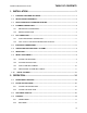
PG14D: Floor Model Gas Pasta Cooker TABLE OF CONTENTS 1. INSTALLATION......................................................................................1 1.1. CHECKING YOUR NEW APPLIANCE.......................................................................................... 1 1.2. INSTALLATION CLEARANCES ................................................................................................... 2 1.3. LEG/CASTER INSTALLATION AND LEVELING ..................................................
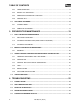
TABLE OF CONTENTS 2.4.3. TIMER OPERATION ............................................................................................................. 17 2.4.4. BASKET LIFT OPERATION.................................................................................................. 17 2.4.5. ADDITIONAL CONTROLLER FUNCTIONS ......................................................................... 17 2.4.6. COOKING TIPS......................................................................................
INSTALLATION PG14D: Floor Model Gas Pasta Cooker 1. INSTALLATION 1.1. CHECKING YOUR NEW APPLIANCE Your new Pitco appliance has been carefully packed into one crate. Every effort has been made to ensure that it is delivered to you in perfect condition. As you unpack your new appliance, inspect each of the pieces for damage. If something is damaged, DO NOT sign the bill of lading. Contact the shipper immediately; the shipper is only responsible for 15 days after delivery.
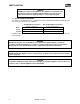
INSTALLATION WARNING DO NOT sit or stand on this appliance. The appliance’s front panel, tank, splash back, tank cover, workshelf, drain board is not a step. Serious injury could result from slipping, falling or contact with hot liquids. 1.2. INSTALLATION CLEARANCES The clearances shown below are for combustible and non-combustible installations and will allow for safe and proper operation of your appliance. Back Sides Counter Combustible Construction Inches (centimeters) 6.0" (15.24cm) 6.0" (15.24cm) 6.
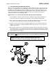
PG14D: Floor Model Gas Pasta Cooker INSTALLATION 1.3. LEG/CASTER INSTALLATION AND LEVELING When you receive your appliance it is completely assembled with the possible exception of the legs (or casters). This appliance must be installed with legs or casters; it cannot be curb mounted. Curb mounting will seriously inhibit this appliance’s ability to effect proper component ventilation. The legs/casters must be installed before connecting the appliance to the gas supply.
INSTALLATION 1.4. PLUMBING CONNECTIONS The plumbing installation should be done by a licensed plumber and must comply with local and national codes. 1.4.1. WATER INLET CONNECTIONS If a faucet or water fill option is equipped on your appliance connections to a potable water supply will be required. If a single water connection is required it is recommended that the appliance is connected to hot water supply. This will greatly decrease the time it takes for the appliance to reach operating temperature.
PG14D: Floor Model Gas Pasta Cooker INSTALLATION 1.5. GAS CONNECTION Your appliance will give you peak performance when the gas supply line is of sufficient size to provide the correct gas flow. The gas line must be installed to meet the local building codes or National Fuel Gas Code ANS Z223.1 and NFPA 54 (latest editions). In Canada, install the appliance in accordance with CSA B149.1 or .2 and local codes.
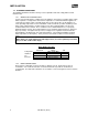
INSTALLATION 1.6. ELECTRICAL CONNECTIONS It is advised that this power supply be plugged into a wall receptacle that is controlled by the ventilation control. This will prevent the appliance from being operated without the ventilator on. If your appliance requires an electrical connection, the power requirements are listed below. Input Voltage Current per unit North America International 120 VAC, 50/60 Hz 220, 230 or 240 VAC 50/60 Hz 1.0 Amp 0.
PG14D: Floor Model Gas Pasta Cooker INSTALLATION WARNING If your appliance is uses line current, it is equipped with an oil proof, electrical supply cord with a three-prong safety plug. This is to protect operators from electrical shock hazard in the event of an equipment malfunction. DO NOT cut or remove the grounding (third) prong from this plug; it should be plugged into a properly grounded three-prong receptacle. 1.7.
INSTALLATION 1.8. INSPECTION Before you begin filling and adjusting the appliance, perform the following visual checks: After the appliance is in its permanent location, check the levelness. Any additional leveling that is necessary can be performed as previously described. Ensure that the probe and high temperature limit is in place and secure. Check the high limit bulb mounting screws to ensure that they are tight.
PG14D: Floor Model Gas Pasta Cooker INSTALLATION 1.9. INITIAL ADJUSTMENTS After your appliance has been properly installed as described in the installation section of this manual, it will need to be adjusted to ensure that it will perform as designed. A qualified person must perform these adjustments. To perform these adjustments the following tools will be needed: • Manometer • Digital Thermometer (Temperature Probe) • DC Voltmeter 1.9.1.
INSTALLATION 1.9.3. PILOT FLAME ADJUSTMENT Perform this procedure with the pilot lit. This procedure requires a DC voltmeter set to a scale of 0-1000 mV. Using test leads with sharp probes will help in taking the required readings. 1. Locate the thermopile wires coming from the thermostat/limit box going to the gas valve. The wire size decreases near the gas valve connections. 2. Using the positive (+) test probe, connect the probe to the high limit wire terminal.
INSTALLATION PG14D: Floor Model Gas Pasta Cooker 1.9.4. MAIN BURNER SYSTEM ADJUSTMENT For the main burners to operate the gas supply valve must be open and the thermostat must be turned on. The main power switch must be on. The main burners receive gas from the main gas supply through the thermostatically controlled valve. When the water temperature drops below the preset temperature the gas control valve opens. The main burners must be adjusted to deliver optimum flame.
INSTALLATION 7. Now that the main burner pressure is set properly you may adjust the main burner flame. Unlock the air collars by loosening the set screw on each collar. Open the main gas valve, (light the pilot if the appliance has a manual pilot) and turn the thermostat to light the main burners. 8. Adjust the shape and size of the main burner flame by raising or lowering the air collars to achieve a soft blue flame with well-defined inner cones.
PG14D: Floor Model Gas Pasta Cooker INSTALLATION CAUTION DO NOT leave the appliance unattended during cleaning. Never let the water level go below the heat tubes. WARNING Wear protective gloves and clothing when cleaning and draining the appliance and when disposing of water. The water is extremely hot and can cause severe injuries. CAUTION Be careful not to disturb the probe and high temperature limit during operation and cleaning of this appliance. 1.10.
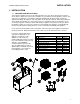
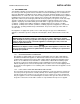
OPERATION 2. OPERATION An operator’s manual for your appliance’s specific control type should be included with this manual. Refer to that manual prior to operating this appliance. 2.1. OPERATIONAL FEATURES The diagram below outlines some of the key operational components of your appliance. Refer to the following sections of this manual to learn more about these features. 1. Cook Tank 2. Controller (Not on all Models) Controls the water temperature inside the cook tank.
PG14D: Floor Model Gas Pasta Cooker OPERATION 15
OPERATION 2.2. FILLING THE APPLIANCE 2.2.1. FILLING THE COOKER TANK It is recommended that the cooker tank is filled with hot water. This will greatly decrease the time it takes for the appliance to reach operating temperature. Refer to the following procedure to fill the cook tank prior to operation. Tank Capacity CAUTION WARNING This appliance is not Water must completely Model Capacity designed for cooking with oil. cover the heat tubes at all PG14D 12 Gal. (45.5 Liters) Fill with potable water only.
PG14D: Floor Model Gas Pasta Cooker OPERATION 2.4. COOKING It is important to keep the cook tank full of water to minimize the chance of boiling the appliance dry and to keep the water at a level that will provide optimum cooking performance. To keep the water at its normal operating temperature, it is best to add water in small amounts. If the appliance is equipped with manual water fill, it is recommended that the fill knobs are set so that water enters the tank slowly during cooking.
OPERATION 2.4.6. COOKING TIPS Rinse pasta after cooking only if it is for cold dishes or if the pasta will NOT be served immediately. Cooked Pasta Volumes For best results when cooking dry pasta, use at least 1 gallon of water for every 1 lb. of dry pasta. 1lb. Dry = Pasta Type Cooked Sticky cooked pasta can be avoided by increasing Spaghetti 10 cups the quantity of water per pound or use of the Angel Hair 8 cups manual fill option while cooking (if equipped).
PG14D: Floor Model Gas Pasta Cooker PREVENTATIVE MAINTENANCE 3. PREVENTATIVE MAINTENANCE 3.1. DAILY PREVENTATIVE MAINTENANCE Performing the preventative maintenance steps below on a daily basis will keep your equipment safe and at peak performance. During the cooking process, starch build up will form on the temperature probes, tank and heating element. If you are producing high quantities of pasta it may be necessary to clean these components more then once a day.
PREVENTATIVE MAINTENANCE 3.2. MONTHLY PREVENTATIVE MAINTENANCE Water can leave mineral deposits inside the tank. Performing the monthly preventative maintenance steps below will keep your equipment safe and at peak performance. If you are producing high quantities of pasta or your water is heavily mineral based, then it may be necessary to clean these components more then once a month. 3.2.1. DELIMING 1. Read the “operation” section of this manual prior to filling or operating the appliance. 2.
PG14D: Floor Model Gas Pasta Cooker PREVENTATIVE MAINTENANCE 3.3.4. TANK Verify that the tank is in good condition. Check for scale build up and inspect for signs of corrosion. Verify that tank is leak free. Check drain overflow (if equipped) for scale build up and debris blockage. 3.3.5. DRAIN SYSTEM Verify that drain valve is in good condition. Check for leaks in the seal area and fitting region. Verify that drain lines are leak free, kink free and in good condition.
TROUBLESHOOTING 4. TROUBLESHOOTING 4.1. POWER FAILURE If electric power is removed for any reason, the appliance will shut down. Wait five minutes after the power is restored before attempting to restart the appliance. This will allow time for any gas that may have accumulated in the burner or tubes to dissipate. To restart the appliance, follow the appliance start up procedure in section 2.2. CAUTION DO NOT attempt to operate this appliance during a power outage. 4.2.
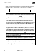
TROUBLESHOOTING PG14D: Floor Model Gas Pasta Cooker 4.4. TROUBLESHOOTING CHART Problem Controller does not activate. Controller displays that it is heating but water will not heat. Probable Causes No power to appliance. Circuit Breaker tripped. Corrective Actions Check main building power supply. Reset circuit breaker. Flip I/0 switch to I position and turn I/0 Switch in 0 position. on controller. Controller not turned on. Turn on controller. Power Cord loose or not connected. Connect power cord.
In the event of problems with or questions about your order, please contact the Pitco Frialator factory at: (603) 225-6684 World Wide Website Address: www.pitco.com In the event of problems with or questions about your equipment, please contact the Pitco Frialator Authorized Service and Parts representative (ASAP) covering your area, or contact Pitco at the numbers listed to the left. MAILING ADDRESS – P.O. BOX 501, CONCORD, NH 03302-0501 SHIPPING ADDRESS – 10 FERRY ST.