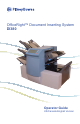
OfficeRight™ Document Inserting System DI380 Operator Guide US/Canada English Version
Statement of FCC Compliance This equipment has been tested and found to comply with the limits for a Class A digital device, pursuant to part 15 of the FCC rules. These limits are designed to provide reasonable protection against interference when the equipment is operated in a commercial environment. This equipment generates, uses, and can radiate radio frequency energy and, if not installed and used in accordance with the instruction manual, may cause interference to radio communications.
Table of Contents If You Need Assistance Contact Information for the USA and Canada.......................iii Chapter 1 Introduction Safety.................................................................................1-2 To The Operator.................................................................1-3 Machine Configurations......................................................1-4 Machine Identification...............................................1-5 to 1-7 Control Panel...........................
Table of Contents Chapter 3 Optical Mark Recognition (OMR) OMR Availability.................................................................3-1 What is OMR?....................................................................3-1 A Brief Overview of OMR on your Machine........................3-1 Levels of OMR on the System............................................3-2 OMR Mark Positions...........................................................3-2 OMR Specifications.........................................
TableContact of Contents Pitney Bowes List If You Need Assistance USA Contacts ▪ Product Name - OfficeRight™ Document Inserting System ▪ Model - DI380 ▪ For frequently asked questions, go to: www.pb.com and click on Customer Support. ▪ To place requests for service or training, go to: www.pb.com and click on My Account. ▪ To order PB supplies and accessories, go to: www.pb.com and click on Online Store. ▪ To view and pay invoices online, go to: www.pb.com and click on My Account.
Table of Contents iv SV61656 Rev.
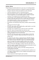
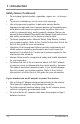
Introduction • 1 Safety Notes Follow these precautions whenever you use your inserting system: • • • • • • • • • • • • • • • • Read all instructions before you attempt to operate the system. Keep the Operator Guide accessible for quick reference. Use this equipment only for its intended purpose. Place the system close to an easily accessible wall outlet. Place the system in an accessible location to allow for proper venting of the equipment and to facilitate servicing.
1 • Introduction Safety Notes (Continued) • • • • • • • Do not place lighted candles, cigarettes, cigars, etc., on the system. To prevent overheating, do not cover vent openings. Use only approved supplies, in particular aerosol duster. Improper storage and use of aerosol dusters or flammable aerosol dusters, can cause an explosive-like condition that could result in a personal injury and/or property damage.
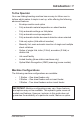
Introduction • 1 To the Operator Your new folding/inserting machine has an easy-to-follow user interface which makes it simple to set up, while offering the following advanced features: • Envelope seal/no seal option • Fully automatic material separation on sheet feeders • Fully automatic settings on fold plates • Fully automatic envelope separation • Fully automatic double document detection when selected • Fold-only option (fold without insertion) • Manually fed, semi-automatic insertion of s
1 • Introduction Processing speed will vary, depending on machine configuration. See Specifications in Chapter 4 for further details. Some models are equipped with OMR (Optical Mark Recognition) scanning. An OMR mark is normally a dark solid line on a sheet of light colored paper that is perpendicular to the direction of paper travel. This line must be thick and dense enough to trigger the system’s OMR scanner.
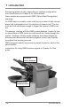
Introduction • 1 Machine Identification 6 3 1 2 5 10 9 12 8 7 11 1 4 Sheet Feeder 1 — This feeder is intended for feeding material that requires folding. In addition, you can set sheet feeder 1 to Manual Feed. In this mode, you can run stapled sets of up to five sheets. The machine waits for each set to be manually fed into sheet feeder 1 before folding and inserting the set automatically. See the Specifications section of this guide for full details of the sets possible.
1 • Introduction Machine Identification (Continued) 6 3 5 10 9 12 8 7 11 1-6 4 SV61656 Rev.
Introduction • 1 3 Insert Feeder — Use this feeder to add additional inserts to your envelope. Material fed from this feeder cannot be folded by the inserter. However, this feeder is especially suited to feeding pre-folded or thicker inserts. 4 Fold Plates 1 and 2 — These create the desired fold in material fed from the sheet feeder(s). The fold plates are automatically set from the control panel.
1 • Introduction Control Panel Control Panel Buttons Default — Press this button to return the machine to its default or ‘standard’ settings. These settings come pre-configured from the factory but can be modified to suit your needs by a Pitney Bowes Service Representative. Job — Press to step through the jobs you’ve programmed into the machine’s memory. The machine will store up to 20 jobs. See page 2-9 for details of programming jobs. Reset Counter — Press to reset the item or batch counter.
Introduction • 1 Display Symbols Used on sheet feeders to signify that the feeder is on without double detection. Used on sheet feeders to signify that the feeder is on with double detection. Used on insert feeder to signify that the feeder is on without double detection. Used on insert feeder to signify that the feeder is on with double detection. Used on sheet feeder 1 to signify that the feeder is set for manual feed. Used on envelope feeder to signify that the feeder is on.
1 • Introduction Display Symbols (Continued) Indicates that the sealer unit is on (automatic envelope sealing). Indicates a C-fold (letter) fold is selected. Indicates a Z-fold (accordion) is selected. Indicates a double fold is selected. Indicates a single fold is selected. Indicates a no-fold insert operation. Indicates a material stoppage. The position of this symbol in the display indicates where the stoppage has occurred. !"# Call for service.
Operation • 2 About this Chapter This chapter explains operation of the machine, assuming the job you want to run is already programmed into the system. If you haven’t programmed the job, please go to Programming Jobs on page 2-9. Connecting Power IMPORTANT! Read the safety information on pages 1-1 and 1-2 of this guide before you connect the machine. Connect the power cord to the socket on the left side of the machine. Plug the power cord into a suitable power outlet.
2 • Operation Select a Job When the machine is turned ON, the display shows the last job run and “Trial Piece Required”. Press the Job button until the job you require is displayed, or press Default if you want to run the machine with your standard job settings. Note: Only a Pitney Bowes Service Representative can modify the default job. If you have material loaded, press Trial Piece. The machine sets itself and runs a test piece for you to check.
Operation • 2 Run a Trial Piece Once material is in place, press Trial Piece so you can check that setup is correct. You can make minor changes to the job settings at this stage if the trial piece needs fine tuning. Enter setup as described on page 2-9, then use the Prev (◄), Next (►) and Change (+/-) buttons as required to modify job settings. When you’ve made the necessary changes, press Setup again to return to run mode. The inserter saves the job with the new settings. Notes: 1.
2 • Operation Setting the Sheet Feeders 1. Adjust the side guides to the width of the material you’re running, then back-off a quarter turn on the side guide control. This sets the correct clearance between the guides and the material. 2. Take the stack of paper and aerate it to ensure that individual sheets are not stuck together. 3. Jog the stack back into alignment. The sheet feeders accept the paper stack aligned in a manner similar to that of a photocopier paper cassette. 4.
Operation • 2 5. Place the paper stack onto the feed deck. Allow the deck to move down and the top of the paper stack to slide under the feed roller. Note: When using both sheet feeders for an accordion fold job, always use sheet feeder 2 for the prime (address-bearing) document. SV61656 Rev.
2 • Operation Setting the Envelope Feeder The envelope feeder feeds the outer envelope for the inserting job you’re running. 1. Adjust the side guides to the width of the envelopes you’re running, then back off half a turn on the side guide control. This sets the correct clearance between the guides and the envelopes. 2. Aerate (fan) the stack of envelopes you’re running. 3. Place envelopes on the feed deck with their flaps up and trailing.
Operation • 2 2. Refer to the label located on the insert feeder. Compare your insert with the diagram. Read off the settings for the insert feeder blue lever (numbers 1 to 9) and the separator shield (letters A to D). Thin Material Thicker Material Thick Inserts, Booklets, etc. 3. Set the blue lever to the number required. 4. Set the separator shield to the letter required. 5. Fan the inserts and place them onto the feed deck. Loading orientation can vary depending on the actual inserts you’re running.
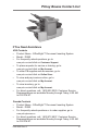
2 • Operation Filling the Sealer When the sealer unit needs refilling, the Add Sealing Solution symbol flashes in the display. Add E-Z Seal® or water in the following way: Note: We recommend E-Z Seal® to minimize scale buildup and the growth of algae. Hinge open the sealer bottle cover located at the rear right hand side of the machine. Remove the bottle. Fill the bottle up to the level indicated. Put the sealer bottle back in position and close the cover.
Operation • 2 Programming Jobs You can program your machine with jobs that you can recall at the touch of a button. All models have 20 operator-programmable jobs plus one default job that your Pitney Bowes Service Representative normally sets. Creating a New Job This section takes you step-by-step through the process of setting up a new job and saving it in memory. Throughout the programming sequence, an asterisk (*) will flash on the display next to the item you’re setting.
2 • Operation Choosing the New Job Number The machine asks for the job number you wish the new settings to be stored under. Use the Change (+/-) buttons to display the job number you want. Notes: • If you use an existing job number, the old settings will be overwritten by the new settings you are about to make. • If you want to find a currently unused job number, press Change (+/-) until you see a job where the display shows no symbols alongside the feeders or in the fold setup area.
Operation • 2 Fold Type Select the type of fold. See the illustrations below. Press Change (+/-) until you see the option you want: C (Letter) Z (Accordion) Double Single Note: For accumulation jobs, DO NOT manually change the fold length dimensions at the “Fold A” and “Fold B” settings (pages 2-17 and 2-18). The machine sets these automati cally.
2 • Operation Setting the Accumulation Function Accumulation, if selected, allows multiple sheets to be fed from the same feeder into the envelope. Press Change (+/-) until you see the option you want. Accumulation: OFF Accumulation is turned off for this job. 1- and 2-station machines... Accumulation: ON Accumulation is turned on for this job. 3-station machines... Accumulation From Main Accumulation is turned on with sheets feeding from the main feeder.
Operation • 2 Setting the First/Main Sheet Feeder The machine automatically selects the first feeder to set, depending on the fold type selected. Note: If you’re collating different sheets using both sheet feeders, you must load the prime (addressed) document into sheet feeder 1 for C and Double folds, and into sheet feeder 2 for Z- or single folds. If you’re using a single sheet only, you may use either sheet feeder or you can use both by choos ing the linked feeder option described below.
2 • Operation Notes about manual feed: 1. The manual feed setting allows you to run stapled sets of up to five sheets to a maximum of 100 lbs. (400g/m2 per set). The maximum compressed thickness of the set after folding must not exceed 0.08 inches (2mm). The machine will wait for manual insertion of each set into sheet feeder 1, after which it will fold and insert the set automatically. 2. When running manual feed mode, sheet feeder 2 becomes inoperable.
Operation • 2 Setting Insert Feeder Select whether you want to use the insert feeder and, if so, how it will be used. Press Change (+/-) until you see the option you want: On Double Detect Feeder on with the double detector operating. (The double detector stops the machine if two or more inserts feed simultaneously from the feeder). On Feeder on without the double detector. Off Feeder turned off for this job.
2 • Operation Sealer This setting only appears if an insertion mode has been selected. Select whether you want to seal envelopes or not. Press Change (+/-) to switch the option on or off: On Turns the sealer unit on for automatic sealing of envelopes. Make sure the sealer water bottle is full of E-Z Seal® or water (see page 2-10). Off Turns the sealer unit off. Envelopes will be ejected unsealed.
Operation • 2 Paper Length Select the paper length. Use the scale on the edge of the front cover. Quick reference: A4 paper length: 297mm US Letter length: 11" (279mm) Press Change (+/-) until the length of your paper (in millimeters) displays. When the paper length is correct, press Next (►) to go to the next setting… Fold A Select the size of the first fold required.
2 • Operation Fold B Select the size of the second fold required. In a manner similar to that of fold A, the machine suggests the correct dimension for the fold. If you want to change the standard setting, press Change (+/-) until the length of fold required displays. The symbol | –––– | shows the fold panel you’re adjusting. When the setting is correct, press Next (►) to advance to the next setting… If you’re programming an inserting job, the envelope depth setting now appears.
Operation • 2 Envelope Stop Select the position of the machine’s envelope stop. The stop has five positions numbered 1 to 5. Setting 3 is the standard setting for normal weight paper with standard folds. A thinner/lighter insert will require a lower setting and thicker/heavier insert a higher setting. Press Change (+/-) until the setting you want is displayed.
2 • Operation Confirming the Job Setup Job setup is now complete. The display will show the complete job setup for you to confirm. If you see a setting that’s incorrect, use the Prev (◄) button to backtrack to the setting and correct it. When you’re satisfied with the job setup, press the Setup button. The machine will save the job in its memory and reset to the new job. When this is complete, the display will show the new job with the message “Trial Piece Required”.
Operation • 2 Testing the Job Load material and press Trial Piece so that you can check if the setup is correct. You can make minor changes to the job settings at this stage if the trial piece needs fine tuning. Press Setup, then use the Prev (◄), Next (►) and Change (+/-) buttons as required to modify job settings. The chart below will help you fine tune your fold settings.
2 • Operation Changing an Existing Job To change an existing job: 1. Enter the setup mode as described on page 2-9. 2. Use the Change (+/-) buttons to display the job you wish to edit. 3. Use the Prev (◄) and Next (►) buttons to display the setting(s) you wish to change. 4. Use the Change (+/-) buttons to change the options/dimensions you wish to amend. 5. Press the Setup button to leave the setup mode and save the changes. Deleting a Job To erase an existing job from memory: 1.
OMR • 3 OMR Availability Your machine may be equipped with Optical Mark Recognition (OMR) scanning, depending on the model you purchased. All models have 20 Operator programmable jobs plus one default job your Pitney Bowes Service Representative normally sets. What is OMR? An OMR mark is normally a dark solid line on a sheet of light colored paper that is perpendicular to the direction of paper travel. This line must be sufficiently thick and dense to trigger the OMR scanner on the system.
3 • OMR You can also set up the insert feeder to be under the selective control of the OMR sheets. As a result, you can use OMR to fill an envelope with a variable number of sheets from one feeder, with or without a supplementary sheet and an insert. A supplementary sheet and folded insert will be nested with the first sheet in the envelope.
OMR • 3 OMR Specifications The mark must be a solid black line between 1pt and 2pts thick (0.014 inch [0.35mm] to 0.027 inch [0.7mm]) and at least 0.393 inch (10mm) wide. Each mark position must be evenly spaced and at least 0.118 inch (3mm) apart. An area around the marks should be kept clear from print and any other marks that might be read by the scanner in error. This area is called the clear zone. There should be no print on the opposing face of the sheet immediately behind the clear zone.
3 • OMR Standard OMR Positions 54mm min 96mm max * Feed Direction for Top 115mm min Scanning (C- and Double Fold) 20mm min Clear Zone 20mm x 115mm min * Clear Zone 20mm x 100mm min 20mm min Vertically center group within area indicated Feed Direction for Bottom Scanning (Z- and Single Fold) 100mm min 69mm max * 27mm min Position OMR marks as follows: C-Fold and Double Fold: Z-Fold and Single Fold: Top scanning, top left corner Bottom scanning, bottom right corner Note: Diagram not to scale 3-4
OMR • 3 Offset OMR Positions 95mm max 125mm min Feed Direction for Top Scanning (C- and Double Fold) 40mm min 20mm min 65mm min 65mm min Bench Mark 20mm min 115mm min 80mm max Feed Direction for Bottom Scanning (Z- and Single Fold) Position OMR marks as follows: C-Fold and Double Fold: Z-Fold and Single Fold: Top scanning, left margin Bottom scanning, right margin Note: Diagram is not to scale SV61656 Rev.
3 • OMR OMR Marks Available This section gives brief descriptions of the OMR marks that can or must be allocated to an OMR Code. Note: Some marks within this section are available as added features which expand OMR capability. Contact your local Pitney Bowes office for details. OMR features will vary, depending on the options you purchased. Benchmark This is a mandatory mark. It must be the first mark of the code and will appear on every page within the set.
OMR • 3 Retiming Mark This mark is mandatory in each group of OMR marks making up the code (see later in this section for an explanation of OMR mark grouping). It allows the machine to recalibrate for accurate scanning. Retiming marks count in the parity calculation. Select Feed (SF1, SF2) These marks are used to control the feed of material from the feeder holding the supplementary sheets/inserts on a set-by-set basis. Therefore you cannot use select feed on a single station machine.
3 • OMR OMR Mark Grouping Each OMR code begins with two fixed marks at the end nearest to the sensor (benchmark and safety mark). These are followed by one, two, or three groups of marks where each group comprises three data marks followed by a fixed mark. Each data mark is present or absent as required to reflect the function desired. Each code must end with a retiming mark. Basic OMR mode uses only Group 1. Enhanced OMR mode uses Group 1 plus Group 2 and/or Group 3, as needed for a particular job.
OMR • 3 Z-Fold and Single Fold Jobs Place marks in the lower right corner of the sheet. Print the marks in bottom-to-top order: Group 3 Group 2 Group 1 (Mandatory) Retiming (fixed if this group is in use) Wrap Around Sequence 1 (WAS1) Wrap Around Sequence 2 (WAS2) Wrap Around Sequence 3 (WAS3) Retiming (fixed if this group is in use) Auto Batch Select Feed 2 Select Feed 1 Retiming (fixed) Parity Not BOC Not EOC Safety (fixed) Benchmark (fixed) Feed Direction Print sheets in normal collation order.
3 • OMR Programming an OMR Job Entering the Setup Mode Open the hinged cover to the right of the display. This exposes the setup buttons. Press Setup. The indicator lights and the machine asks for an access code. This code prevents unauthorized personnel from changing the machine’s settings. Use the Change (+/-) buttons to select the access code 71. Press Next (►) to advance to the next setting… Choosing the New Job Number The machine asks for the job number you wish the new settings to be stored under.
OMR • 3 Selecting the OMR Functions Press Change (+/-) until you see the option you want. Note that the options shown will depend on the OMR functionality that your machine has. Details of standard and offset OMR positioning appear on pages 3-4 and 3-5. OMR off OMR is turned off for this job. OMR on OMR is turned on (Basic Scanning) for this job with standard OMR mark positioning. OMR + Sequence Basic scanning + Wrap Around Sequence scanning for this job with standard OMR mark positioning.
3 • OMR Notes: OMR (Basic scanning) offers the following scanning functions: Benchmark Safety End-of-Collation absent Beginning-of-Collation absent Parity Retime Select feed/autobatch offers the following scanning functions: Select feed 1 Select feed 2 Autobatch Retime Sequence offers: Three wrap-around page sequence marks Retime The maximum pages per set that can be fed from either sheet feeder 1 or 2 when using the
OMR • 3 Fold Type Select the type of fold. Press Change (+/-) until you see the option you want: Note: For OMR scanning jobs, DO NOT manually change the fold length dimensions for Fold A and Fold B. These are set automatically by the machine. C — Letter Z — Accordion Double Single When you select either a C-fold or a double fold, the machine automatically selects top sheet feeder 1 as the scanning feeder.
3 • OMR Setting the Main (Scanning) Sheet Feeder Press Change (+/-) until you see the option you want: On Double Detect Feeder is on with the double detector operating. (The double detector stops the machine if two or more sheets feed simultaneously from the feeder.) On Feeder on without the double detector. When the Sheet Feeder is set as required, press Next (►) to advance to the next setting… 3-14 SV61656 Rev.
OMR • 3 Setting Select/Supplementary Feeders Press Change (+/-) until you see the option you want: If sheet feeder 1 is the main/ scanning feeder, you can program sheet feeder 2 and/or the insert feeder for normal (one per envelope) feeding or select feeding. If sheet feeder 2 is the main/scanning feeder, you can program sheet feeder 1 and/or the insert feeder for normal (one per envelope) feeding or select feeding.
3 • OMR Adjustment of OMR Scanner In order for OMR scanning to work correctly, it is important to ensure that the scanning heads are positioned in line with the scan dash (OMR) marks printed on the material. To locate the scanning head for the top sheet feeder 1, open the top cover. You’ll find the scanning head at the rear of the machine. To locate the scanning head for the bottom sheet feeder 2, remove both sheet feeder 2 and the fold plate situated below sheet feeder 2.
OMR • 3 Fold a sheet of material in half and measure the distance from the side of the form to the middle as shown. For an A4 size form, this measurement is 105mm. For a letter-size sheet (8.5 x 11 inches), it is 108mm. Now measure the distance from the edge of the form to the middle of the scan dash marks, as shown. Then subtract this measurement from the half-fold measurement. 10mm 105mm Example: For an A4 size form, the half fold measurement is 105mm.
3 • OMR OMR Troubleshooting Error Recovery for OMR Jobs: If the machine stops during an OMR job, and indicates one of the error messages listed below, press the Clear Deck key. Any envelope at the insertion area will eject into the stacker. The remaining pages of the current set will feed/fold and eject into the stacker. You can insert them into the envelope by hand. The first page of the next set will prefeed into the feed rollers and stop.
OMR • 3 Message Action Bad OMR Code length Code type on paper does not match the setup. Example: setup has OMR+ Sequence but paper has OMR + Select Feed + Sequence. Bad OMR Code format A re-timing scan mark is missing. Check material. Example: mark 6 is missing from a 10 mark code. Expected 1st Sheet of set The BOC mark (position 4) was present when it was not expected. First page of the set was expected. Not a new Envelope The BOC mark (position 4) was absent when it was expected.
3 • OMR 3-20 SV61656 Rev.
Reference • 4 Changing the Display Language To change the language of the display… 1. Open the hinged cover to the right of the display. This exposes the setup buttons. Press Setup. The indicator lights and the machine asks for an access code. 2. Use the Change (+/-) buttons to select the access code 99. 3. Press Next (►) to select the languages option. 4. Use the Change (+/-) buttons to scroll through the languages.
4 • Reference Removal and Replacement of the Sheet Feeder Trays To remove… Lift the rear of the tray slightly and pull it straight out from the machine. Note: If the tray is loaded, gently hold the material in place to prevent it sliding forward as you remove the tray. To replace… Place the tray into its location guides in the side frames. Lift the rear of the tray slightly and push it into the machine. The tray will automatically drop into its correct position.
Reference • 4 Access to Carriage Assembly (Two- and Three-station machines only). You can pull the carriage assembly outward to gain access. Remove the insert feeder and fold plate 2 first. Access to Envelope Feeder Area To gain access… Pull the release lever in the direction of the arrow, right. Lift the envelope area feed rollers to gain access. To relatch feed rollers… Release the envelope area feed rollers and let them rest in position. Push the rollers firmly down until they latch into position.
4 • Reference Access to the Envelope Inserting/Sealing Area You can access the insertion and sealing areas by lifting the tinted plastic cover and lowering the envelope inverter access door. See the figure, right. Access to the Sheet Feed Area To gain access… Open the top cover. Squeeze the two blue handles together and pivot the guide assembly to the right to gain access. To relatch… Squeeze the two blue handles together and pivot the guide assembly back to its closed position.
Reference • 4 General Troubleshooting Problem Remedy Page MACHINE Blank Screen No power. Check that power cord is firmly con- 1-1 nected and wall socket is switched ON. Machine not switched ON. Turn power switch (located on left side) ON. 2-1 Machine will not Operate Cover open. Check that ALL covers are closed— check display for cover information. Feed trays/fold plates not located correctly. Remove and relocate all feeders and fold plates. Make sure they are fully seated.
4 • Reference Problem Remedy Page ENVELOPES Poor Envelope Feed Envelope side guides set incorrectly. Set guides to envelope width and back off 1/2 turn. 2-6 Poor envelope quality. Check that envelopes are not 4-15 curled. Try a new box of envelopes. Make sure to fan stack before load- 2-6 ing. Envelopes loaded incorrectly. Load envelopes flap side up with the flap feeding last. 2-6 Envelopes Fail to Open Envelopes loaded incorrectly.
Reference • 4 Problem Remedy Page SHEETS Poor Sheet Feed Feeder not selected to feed. Check job setup. 2-13 Sheet feeder side guides set incorrectly. Set guides to sheet width and back off 1/4 turn. 2-4 Sheets loaded incorrectly. Make sure to fan stack before loading. 2-4 Multiple Sheets Feed when One Is Expected Manual feed mode is selected. Check job setup and manual feed lever position. 2-2 Sheets loaded incorrectly. Make sure to fan stack before loading.
4 • Reference Problem Remedy Page INSERTS Poor Insert Feed Feeder not selected to feed. Check job setup. 2-3, 2-20 Insert feeder side guides set incorrectly. Set guides to insert width and back off 1/4 turn. 2-6 Insert feeder sepa- Make sure the two insert feeder rator adjustments adjustments (lever and separator incorrect. shield) are set correctly for the type of insert you’re running. 2-7 Inserts loaded incorrectly. Make sure to fan stack before loading.
Reference • 4 Problem Remedy Page DOUBLE DETECT Machine Stops for Doubles that Aren’t There or Feeds Doubles without Stopping Double detect is not turned ON. Check double detect status. Double detect icon will appear alongside all items for which double detect is ON. Correct loading or job setup as nec- Chapter essary. 2 Double detect is not correctly calibrated. SV61656 Rev. A Run a trial piece whenever you load 2-3 a new batch of material to recalibrate double detect.
4 • Reference Error Messages Message Action CALL SERVICE Power machine off and on. If message still displays, call for service. CHECK /CLEAR FEEDER The feeder indicated has failed to feed material. Remove material from the feed tray, reload and restart machine. CHECK FEEDER The feeder indicated is not located correctly. Remove tray and relocate. Also check loading of material in indicated feeder. CHECK FOLD PLATE Fold plate indicated is not located correctly. Remove fold plate and relocate.
Reference • 4 Message Action CLOSE MAN ADV COVER The manual advance knob door is not fully closed. Close door. DEFLECTOR ERROR The half fold function is not possible due to a fault. Remove fold plates and check for any material. DOUBLE FEED A double feed was detected from the feed tray indicated. Remove the material from the machine and restart. If double feeds persist, request another trial piece. DOUBLE FEED A double feed was detected from the feed tray CHECK STACKER indicated.
4 • Reference Message Action STREAM FEED The machine has detected two sheets fed CHECK STACKER together from the feed tray indicated. Remove the stream feed from the stacker. Reload machine and restart. SYSTEM ERROR POWER DOWN A fault was detected in the main software. Switch machine off and on and retry. If problem persists, call service. TRAY EMPTY Tray indicated has no material. Reload tray and press Start. 4-12 SV61656 Rev.
Reference • 4 Material Specifications Sheet Feeders Minimum Sheet Size: 5 in. (127mm) width 5 in. (127mm) length Maximum Sheet Size: 9 in. (229mm) width 16 in. (406mm) length Paper Weights: 16 lb. (60g/m2) minimum (non OMR) 18 lb. (70g/m2) minimum (OMR) 32 lb. (120g/m2 ) maximum Fold Configurations: Material length limits before folding Single fold: C (letter fold): Z (accordion fold): Double fold: 5 in. (127mm) - 12 in. (315mm) 6 in. (150mm) - 14 in. (356mm) 8 in. (201mm) - 14 in. (356mm) 12 in.
4 • Reference Fold Type and Overall Thickness Limits The table below shows the maximum number of sheets that can be accumulated or collated for each fold type, based on different weights of paper. Important! DO NOT program jobs that exceed these maximums or impose them by OMR code printing and/or OMR selective feed.
Reference • 4 Insert Feeder Minimum Insert Size: 5 in. (127mm) width 3.25 in. (82mm) length Maximum Insert Size: 9 in. (230mm) width 6 in. (152mm) length Paper Weights: 20 lbs. (75g/m2) min. (non-folded cut sheet) 50 lbs. (180g/m2 ) max. (single sheet) 16 lbs. (60g/m2) min. (folded material) And inserts of up to a maximum com- pressed thickness of 0.078 in. (2mm) Pre-folded or single panel Inserts should be fed from the Insert Feeder.
4 • Reference Minimum Envelope Size: 3.5 in. (88mm) depth 8.5 in. (220mm) width Maximum Envelope Size: 6.5 in. (164mm) depth WIDTH 9.5 in. (242mm) width DEPTH Envelope Feeder Envelope Weights: 17 lbs. (65g/m2) minimum 26 lbs. (100g/m2) maximum Envelope Tray Capacity: Up to a maximum of 100 24 lb. (90g/m2) envelopes. End Clearance: End clearance between insert and envelope is a minimum of 0.236 in. (6mm) at each side, that is, a minimum of 0.472 in (12mm) overall.
Reference • 4 Machine Specifications Physical Dimensions: Length Depth Height Weight 30.4 in. (773mm) 22.3 in. (568mm) 20.6 in. (525mm) 121 lbs. (55kg) Noise Level (Running): 73dBA Electrical: 120V, 60Hz, 6.
4 • Reference 4-18 SV61656 Rev.
JOBS Jobs Use the table below to keep a note of the jobs you’ve programmed into the system. Job Description Default 1 2 3 4 5 6 7 8 9 SV61656 Rev.
JOBS Job Description 10 11 12 13 14 15 16 17 18 19 20 5-2 SV61656 Rev.
Appendix A —Glossary Term Definitions Accordion Fold See Z-Fold. Address-Bearing Document The document on which the destination address appears. In OMR applications, the addressbearing document is often the control or primary document. Accumulation Mail piece contents assembled at a specific point in a paper transport. Also known as a “collation.” Accumulator A mechanical buffer in a paper transport where sheets, inserts or collated sets are merged.
Appendix A —Glossary Term Definitions C-Fold A type of trifold in which a sheet is folded in thirds with the top and bottom panels facing in the same direction. As seen from the edge, the fold looks like the letter “C.” Compare with Z-Fold. Cancel To stop or interrupt a process; to invalidate or undo a choice or option. Card A type of insert, heavier than a slip, thick enough to be mailed (≥ 0.007 inches, U.S.). Cards are not folded.
Appendix A —Glossary Term Definitions DD An abbreviation for Double Detect. Depth Clearance (Envelope) The required clearance between the depth of a mailing envelope and the depth of its contents (the assembled collation). Envelope depth is measured from the flap fold to the bottom of the envelope. If depth clearance is not adequate, the contents of the envelope will extend beyond the envelope flap fold, making the envelope difficult if not impossible to close and seal.
Appendix A —Glossary Term Definitions End-of-Collation A machine function that detects the presence or absence of an end-of-collation mark (see below). This mark signals an inserting system that a collation is complete. End-of-Collation Mark A mark designating a particular sheet or insert as the last page of a collation. The presence or absence of the mark can signal end-of-collation. Envelope Depth The dimension of an envelope measured from its flap fold to its opposite (bottom) edge.
Appendix A —Glossary Term Definitions Flap Depth The distance between the envelope flap fold and that part of the flap farthest opposite. Flap First An envelope orientation where the envelope feeds flap first. Flaps are normally closed but not sealed. Flap Last An envelope orientation where the envelope feeds flap last. When loaded, flaps are normally closed but not sealed. Flap side down An envelope orientation where the envelope feeds with the flap side facing down.
Appendix A —Glossary Term Definitions Item One or more sheets or inserts from a single feeder that go into a mail piece. Job A quantity of mail pieces to be generated with a fixed setup arrangement. Job Run The process of creating mail defined by a particular setup instruction. Job Settings The collection of values that define how a mail piece is to be created by the hardware. A set of instructions within the machine used for assembling a single job or mail run.
Appendix A —Glossary Term Definitions Mark Present A condition is which the presence of an OMR mark triggers a machine function. When the mark is absent, no function is triggered. Material A broad term referring to any type of paper in any form that a paper handling device can process. Material includes sheets, cards, slips, envelopes, pre-folded and pre-collated sets and booklets. Maximum Number of sheets The maximum number of sheets an inserter system can handle reliably.
Appendix A —Glossary Term Definitions Page Count The number of pages fed per collation. Paper Path In a paper transport system, the path followed by material as it moves through the machine. Paper/Sheet Length The dimension of a sheet or insert as measured in the direction of feed. Paper/Sheet Width The dimension of a sheet, insert or envelope as measured at right angle with respect to paper length. Paper Weight A measure of the “substance” or heft of paper.
Appendix A —Glossary Term Definitions Power-On Reset Re-initializing a device by turning the power off, then on. Run A single instance of a job. Scan Window A designated area on a sheet or insert reserved solely for OMR marks. Sometimes referred to as the “scan zone.” The start scan mark is located in this zone and begins the scanning process. There must be no printed material in the scan window other than the OMR marks. Scanner A device that reads OMR dash marks.
Appendix A —Glossary Term Definitions Slip A type of insert, generally a single-thickness document that fits into an envelope without folding. Stacker An output device that stacks finished mail pieces in an orderly fashion. Gravity stackers stack materially vertically. Power stackers usually stack material in a horizontal, shingled stream. Tabbed Insert A pre-folded insert whose open edge is closed by a sticker or piece of tape. The material used to secure the closure is called a “tab.
Appendix A —Glossary Term Definitions User Interface The controls and display that allow a user to interact with a machine, computer or software application. Wedge Sometimes referred to as a material prop or sled, a wedge raises the feed angle of a stack of material. It’s designed to help shingled stacks of material feed reliably. The position of the wedge is operator-adjustable. Tri-Fold A sheet folded in thirds. See C-Fold and Z-Fold.
Appendix A —Glossary A-12 SV61656 Rev.
Index A C AC Adapter Safe Use of with Stacker 1-2 Accordion Fold Definition A-1 Accumulation Definition A-1 Setting up Multiple Feed 2-12 AC Power, Connect 2-1 Additional Set, Definition A-1 Sheet, Definition A-1 Address in Wrong Positiion 4-7 Too High, Correcting 2-21 Too Low, Correcting 2-21 Address-Bearing Document Definition A-1 Advance Knob Using the 4-1 Assistance, Getting v Auto Batch OMR Mark 3-7 C-Fold Definition A-2 Cancel Definition A-2 Card Definition A-2 Carriage Assembly Accessing the 4-3 C
Index Controls and Features (Continued) Fold Plates 1 and 2 1-7 Insert Feeder 1-7 Manual Advance Knob 1-7 Measuring Scale 1-7 Sealer Bottle 1-7 Sheet Feeder 1 1-5 Sheet Feeder 2 1-5 Cover Definition A-2 Customer Service, Calling v D DD (Double Document) Definition A-3 Default Control 1-8 Definition A-3 Delete A Job 2-22 Control 1-8 Depth Clearance (Envelope) 4-16 Definition A-3 Dimensions, Machine 4-17 Display Blank Screen 4-5 Language, Changing the 4-1 Location and Description 1-7 Symbols 1-9 Document Def
Index Error Messages Call Service 4-10 Check/Clear Feeder 4-10 Check Feeder 4-10 Check Fold Plate 4-10 Check Inverter 4-10 Check Last Mail Piece 4-10 Clear Fold Plate 4-10 Clear Insertion Area 4-10 Clear Moistener 4-10 Clear Sealer 4-10 Close Cover 4-10 Close Man Adv Cover 4-11 Deflector Error 4-11 Double Feed 4-11 Double Feed Check Stacker 4-11 Fold Plates not Set 4-11 Manual Feed Timeout 4-11 Paper Short Check Stacker 4-11 Paper Short Timeout 4-11 Set Lever 4-11 Stream Feed 4-11 Stream Feed Check Stacker
Index Definition A-5 Item Definition A-6 J Job Changing an Existing 2-22 Control 1-8 Creating a New 2-9 Definition A-6 Deleting a 2-22 Listing, Operator Record 5-1 Number, Choosing A 3-10 Number, Choosing a New 2-10 Programming 2-9 Run, Definition A-6 Selecting a 2-2 Settings Making Minor Changes to 2-21 Settings, Definition A-6 Setup, Confirming 2-20 Setup, Definition A-6 Testing a 2-21 L Language Display, Changing the 4-1 Leading Edge Definition A-6 Linked Feeders Definition A-6 Linking Feeders 2-13 M
Index OMR (Continued) Mark Definition 1-4 Grouping 3-8 Marks Available 3-6 Definition A-7 Position of 3-2 Typical, Illustration of 3-1 Offset Mark Positions 3-2 Overview of 3-1 Parity 3-6 Positions Offset 3-5 Standard 3-4 Programming a Job with 3-10 Retiming Mark 3-7 Safety Mark 3-6 Scanner Adjustment 3-16 Select Feed (SF1, SF2) 3-7 Setting the Mode 2-10 Specifications 3-3 Standard Mark Positions 3-2 Troubleshooting 3-18 Wrap Around Sequence (WAS1, WAS2, WAS3) 3-7 Open Edge First, Definition A-7 Edge Last,
Index S Setup (Continued) Choosing the New Job Number 2Safety 10 Mark (OMR) 3-6 Confirming the Job 2-20 Notes 1-1,1-2 Control 1-8 Scanner Creating a New Job 2-9 Definition A-9 Deleting a Job 2-22 Scanning Functions Envelope Depth, Setting 2-18 OMR, Basic 3-12 Envelope Feeder, Setting 2-6 Select Feed/Autobatch 3-12 Envelope Stop, Setting 2-19 Sequence 3-12 First/Main Sheet Feeder, SetScan Window ting 2-13 Definition A-9 Fold A, Selecting Size of 2-17 Screen is Blank 4-5 Fold B, Setting Size of 2-18 Sealer F
Index Sheet Feeder (Continued) Setting the Main Scanning 3-14 Trays, Removing the 4-2 Feed Poor 4-7 Multiple Feeds 4-7 Set, Definition A-9 Size Specification 4-13 Shingle Definition A-9 Single sheet Definition A-9 Slip Definition A-10 Specifications Machine Compliance 4-17 Dimensions 4-17 Electrical 4-17 Fold Modes 4-17 Noise Level 4-17 Speed 4-17 Material 4-13 Double Detect Material Range 413 Envelope Depth Clearance 4-16 End Clearance 4-16 Flap and Throat Requirements 4-16 Tray Capacity 4-16 Weights 4-16
Index Troubleshooting (Continued) Envelopes Fail to Open 4-6 Error Recovery for Accumulation Jobs 3-18 for Empty Feeders 3-18 Insertion Problems 4-5 Machine will not Operate 4-5 Multiple Sheets Feed when One Is Expected 4-7 OMR 3-18 Poor Envelope Feed 4-6 Poor Folding 4-7 Poor Insert Feed 4-8 Poor Sheet Feed 4-7 Table 4-5 U Uncollated Sheet Definition A-10 User Interface Definition A-11 W Wedge Definition A-11 Window Definition A-11 Wrap-Around Sequencing Definition A-11 Wrap Around Sequence (WAS1, WAS2,
1 Elmcroft Rd. Stamford, Connecticut 06926-0700 www.pitneybowes.com PB Form SV61656 Rev B (5/06) Printed in the USA or Canada Printed on recyclable paper *SV61656REVA* 5500 Explorer Drive Mississauga, Ontario L4W5C7 www.pitneybowes.