
Datasheet


Technical data
© 2005 Copyright Pizzato Elettrica
General Catalog 18
page 2/5
2
General Catalog 18
page 2/6
© 2005 Copyright Pizzato Elettrica
2
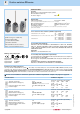
Main data
Metal housing, one conduit entry
Protection degree IP67
17 contact blocks available
28 actuators available
M12 assembled connector versions
Silver contacts gold plated versions
Position switches FD series
Markings and quality marks:
Approval IMQ: EG605
Approval UL: E131787
Approval CSA: LA 93682-1
Approval EZU: 1010151
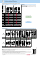
Electrical data Utilization categories
Alternate current: AC15 (50...60 Hz)
Ue (V) 250 400 500
Ie (A) 6 4 1
Direct current: DC13
Ue (V) 24 125 250
Ie (A) 6 1,1 0,4
Alternate current: AC15 (50...60 Hz)
Ue (V) 24 120 250
Ie (A) 4 4 4
Direct current: DC13
Ue (V) 24 125 250
Ie (A) 4 1,1 0,4
Thermal current (Ith): 4 A
Rated insulation voltage (Ui): 250 VAC 300 VDC
Protection against short circuits: fuse 4 A 500 V type gG
Pollution degree: 3
with 5 poles
M12 connector
Thermal current (Ith): 2 A
Rated insulation voltage (Ui): 30 VAC 36 VDC
Protection against short circuits: fuse 2 A 500 V type gG
Pollution degree: 3
with 8 poles
M12 connector
Alternate current: AC15 (50...60 Hz)
Ue (V) 24
Ie (A) 2
Direct current: DC13
Ue (V) 24
Ie (A) 2
Thermal current (Ith): 10 A
Rated insulation voltage (Ui): 500 VAC 600 VDC
400 VAC for contact blocks 20, 21, 22, 33, 34
Protection against short circuits: fuse 10 A 500 V type aM
Pollution degree: 3
without
connector
Installation for safety applications:
Use only switches marked with the symbol . The safety circuit must always be connected with the NC contacts (normally closed
contacts: 11-12, 21-22 or 31-32) as stated in the standard CEI EN 60947-5-1, encl. K, par. 2. The switch must be actuated with at
least up to the positive opening travel shown in the travels diagrams on page 6/14. The switch must be actuated at least with the
positive opening force, shown in brackets, underneath each article, near the value of the min. force.
In conformity with requirements requested by:
Low Voltage Directive 73/23/EEC and subsequent modications and completions.
Machinery Directive 98/37/EEC.
Electromagnetic Compatibility 89/336/EEC and subsequent modications and
completions.
Positive contact opening in conformity with standards:
IEC 947-5-1, EN 60947-5-1, CEI EN 60947-5-1, VDE 0660-206.
In conformity with standards:
IEC 947-5-1, IEC 337-1, EN 60947-5-1, CEI EN 60947-5-1, CEI 17-45, EN 50041,
CEI 17-31, IEC 204-1, EN 60204-1, CEI 44-5, EN 1088, EN ISO 12100-1, EN ISO
12100-2, IEC 529, EN 60529, CEI 70-1, NFC 63-140, VDE 0660-200, VDE 0113,
CENELEC EN 50013.
Approvals:
IEC 947-5-1, UL 508, CSA C22-2 nr.14.
General data
Ambient temperature: from -25°C to +80°C
Version for operation in ambient temperature from -40°C to +80° C on request
Max operating frequency: 3600 operations cycles
1
/hour
Mechanical endurance: 20 million operations cycles
1
Assembling position: any
(1) One operation cycle means two movements, one to close and one to open contacts, as foreseen
by IEC 947-5-1 standard.
Cross section of the conductors (exible copper wire)
Contact blocks 20, 21, 22, 33, 34: min. 1 x 0,34 mm
2
(1 x AWG 22)
max. 2 x 1,5 mm
2
(2 x AWG 16)
Contact blocks 5, 6, 7, 9, 10, 11, 12, 13, 14, 15, 16, 18: min. 1 x 0,5 mm
2
(1 x AWG 20)
max. 2 x 2,5 mm
2
(2 x AWG 14)
Contact block 2: min. 1 x 0,5 mm
2
(1 x AWG 20)
max. 2 x 1,5 mm
2
(2 x AWG 16)
Housing
Metal housing, coated with baked epoxy powder
One threaded conduit entry
Protection degree: IP67
For the correct installation of all articles, please see “Utilization requirements” chapter, from page 6/1 to page 6/4.