EP4650/EP5550 User Guide
Copyright © 9 May 2013 by Planar Systems, Inc. All rights reserved. Contents of this publication may not be reproduced in any form without permission of Planar Systems, Inc. Trademark Credits Windows™ is a trademark of Microsoft Corp. All other companies are trademarks or registered trademarks of their respective companies. Disclaimer The information contained in this document is subject to change without notice. Planar Systems, Inc. makes no warranty of any kind with regard to this material.
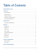
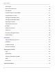
Table of Contents EP4650/EP5550 User Guide . . . . . . . . . . . . . . . . . . . . . . . . . . . . . . . . . . . . . . . . . . . . . . . . . . . . . . . . . . . . . . . . . . . . . . . . i Introduction . . . . . . . . . . . . . . . . . . . . . . . . . . . . . . . . . . . . . . . . . . . . . . . . . . . . . . . . . . . . . . . . . . . . . . . . . . . . . . . . . . . . . . .1 Safety Information . . . . . . . . . . . . . . . . . . . . . . . . . . . . . . . . . . . . . . . . . . . . . . . . . . . . . . . . . .
Table of Contents OSD Keypad . . . . . . . . . . . . . . . . . . . . . . . . . . . . . . . . . . . . . . . . . . . . . . . . . . . . . . . . . . . . . . . . . . . . . . . . . . . . . . . . . . . .19 Remote Control Receiver . . . . . . . . . . . . . . . . . . . . . . . . . . . . . . . . . . . . . . . . . . . . . . . . . . . . . . . . . . . . . . . . . . . . . . . .20 LED Indicators . . . . . . . . . . . . . . . . . . . . . . . . . . . . . . . . . . . . . . . . . . . . . . . . . . . . . . . . . . . . . . . .
Table of Contents Specifications . . . . . . . . . . . . . . . . . . . . . . . . . . . . . . . . . . . . . . . . . . . . . . . . . . . . . . . . . . . . . . . . . . . . . . . . . . . . . . . . . . . . 78 Troubleshooting . . . . . . . . . . . . . . . . . . . . . . . . . . . . . . . . . . . . . . . . . . . . . . . . . . . . . . . . . . . . . . . . . . . . . . . . . . . . . . . . . 80 Accessing Planar’s Technical Support Website . . . . . . . . . . . . . . . . . . . . . . . . . . . . . . . . . . . . . . . . .
Table of Contents iv EP4650/EP5550 User Manual
Introduction The EP4650/EP5550 is a 46” or 55” diagonal edge-lit LED LCD display that can be wall mounted, ceiling mounted or mounted on a stand. The display can be portrait or landscape. The EP4650 and EP5550 are ultra slim and have an aspect ratio of 1.77 (16:9). The EP4650/EP5550 have a native HD (1920 x 1080) resolution and both accept a wide range of input pictures from VGA to 1080p.
Safety Information Safety Information Before using the EP4650/EP5550, please read this manual thoroughly to help protect against damage to property, and to ensure personnel safety. • Be sure to observe the following instructions. • For your safety, be sure to observe ALL the warnings detailed in this manual. • For installation or adjustment, please follow this manual’s instructions, and refer all servicing to qualified service personnel.
Important Safety Instructions Important Safety Instructions 1 Read these instructions. 2 Keep these instructions. 3 Heed all warnings. 4 Follow all instructions. 5 Do not use the EP4650/EP5550 near water. 6 Clean the LCD screens with an LCD screen cleaner or LCD wipes. 7 Do not install near any heat sources such as radiators, heat registers, stoves or other apparatus (including amplifiers) that produce heat. 8 Do not defeat the safety purpose of the polarized or grounding type plug.
Recommended Usage 16 Slight pressure on the LCD will cause distortion of the image. Heavier pressure will cause permanent damage. Displays should be mounted where viewers cannot touch the screen or insert small objects in the openings that will create hazards by contacting bare conductive parts. 17 The front polarizer is soft and subject to scratches from sharp objects. The polarizer is a thin sheet of film laminated to the outside layer of glass on the LCD screen.
European Union Disposal Information European Union Disposal Information Français English ■ Disposal of old Electrical & Electronic Equipment (Applicable throughout the European Union and other European countries with separate collection programs) ■ Mise au rebut des équipements électriques et électroniques usagés (Valable dans l’ensemble de l’Union Européenne ainsi que dans les pays européens disposant de programmes distincts de collecte des déchets) Deutsch ■ Entsorgung von elektrischen & elektronische
Normal Usage Guidelines Normal Usage Guidelines Normal use of the LCD is defined as operating in the open air to prevent heat buildup, and without direct or indirect heat sources such as lighting fixtures, heating ducts, or direct sunlight that can cause the modules to experience high operating temperatures. For all modules, do not block fans or ventilation openings.
Cleaning the EP4650/EP5550 Cleaning the EP4650/EP5550 If dust has collected on the power plug, removed the plug from the outlet and clean off the dust. Dust build-up may cause a fire. Remove the power plug before cleaning. Failure to do so may result in electrical shock or damage. Keep the following points in mind when cleaning the surface of the EP4650/EP5550: • When the surface of the EP4650/EP5550 becomes dirty, wipe the surface lightly with a soft clean cloth.
Package Contents Package Contents Unpacking the EP4650/EP5550 The EP4650/EP5550 is packed in a cardboard box and may be banded as part of two types of custom pallets, depending on the number of displays shipped. The EP4650/EP5550 is packed using foam to protect it during shipping. Before unpacking the EP4650/EP5550, prepare a stable, level and clean surface near a wall outlet. 1 Place the LCD panel box in an upright position and remove the carton locks from the bottom first.
Unpacking the EP4650/EP5550 3 Remove the accessory bag and packing list.
Contents of the Accessory Kit Contents of the Accessory Kit Part 10 Picture Quantity VGA Cable (D-sub) 1 USB Drive 1 Power cord 1 IR extender cable 1 OSD Remote (AAA batteries included) 1 EP4650/EP5550 User Manual
Dimensions Dimensions EP4560 - Front LQ PP LQ PP LQ PP LQ PP LQ PP LQ PP LQ PP EP4650/EP5550 User Manual 11
EP4560 - Rear EP4560 - Rear LQ PP LQ PP LQ PP LQ PP LQ PP LQ LQ PP PP ; 0 02817,1* +2/(6 )25 0(',$ 3/$<(5 12 LQ PP LQ PP LQ PP EP4650/EP5550 User Manual LQ PP ; 0 9(6$ 02817,1* +2/(6
EP4560 - Side EP4560 - Side +' 6', 9: 237,21 LQ PP LQ PP LQ PP Standard Inputs RS232C LAN DisplayPort HDMI 1 HDMI 2 DVI-D VGA IR PC Audio Audio Extender Out In EP4650/EP5550 User Manual Component Audio In S-Video Video Audio In 13
Optional HD-SDI/VW Inputs Optional HD-SDI/VW Inputs SDI IN SDI IN SDI OUT DVI OUT VGA OUT EP5550 - Front LQ PP LQ PP LQ PP LQ PP 14 LQ PP EP4650/EP5550 User Manual LQ PP LQ PP
EP5550 - Rear EP5550 - Rear LQ PP LQ PP LQ PP ; 0 02817,1* +2/(6 )25 0(',$ 3/$<(5 LQ PP LQ PP LQ PP LQ PP LQ PP LQ PP LQ PP EP4650/EP5550 User Manual LQ PP ; 0 9(6$ 02817,1* +2/(6 15
EP5550 - Side EP5550 - Side HD-SDI/VW 237,21$/ OPTION +' 6', 9: .
Installing an EP4650/EP5550 Installing an EP4650/EP5550 This section explains how to install an EP4650/EP5550. We suggest that you read the entire section before you attempt to install the unit. Before You Begin Make sure you have all the items in these lists before you begin unpacking and installing your EP4650/EP5550(s).
Prepare Your Installation Location Prepare Your Installation Location You should have prepared the area where you will install the unit. If custom enclosures are part of the installation, they must be fully designed to accommodate the installation of the displays, as well as the installed unit and ventilation and cooling requirements.
Operating the EP4560/EP5550 Operating the EP4560/EP5550 OSD Keypad The OSD keypad is located on the rear of the display.
Remote Control Receiver OSD Keypad Buttons Menu Right/Increase value Menu Left/Decrease value ▲ Menu Up ▼ Menu Down Menu/Exit Menu/Exit Remote Control Receiver The remote control receiver is located near the keypad on the rear of the display. Use the IR extender cable for operating the remote from the front of the display.
LED Indicators LED Indicators The LED indicator light is located on the rear of the display near the keypad. The following table explains what the different colors and blink patterns mean.
Using the Remote Control Using the Remote Control Below is a picture of the remote control and its corresponding Hex codes. See the following page for button descriptions and Hex codes.
Using the Remote Control Num 1 Function INFO 2 Customer Code Hex Code 40AF 04FB Provides source and resolution information 40AF 1CE3 Turns the EP4650/EP5550 on and off Description 3 VGA 40AF 07F8 Selects the PC’s VGA source 4 DVI 40AF 08F7 Selects the PC’s DVI source 5 HDMI 1 40AF 09F6 Selects the HDMI source 1 6 COMP 40AF 0AF5 Selects the Component source 7 AV 40AF 0BF4 Selects the Composite video source 8 HDMI 2 40AF 0CF3 Selects the HDMI source 2 9 P-position
Locking/Unlocking the OSD Menus Num Function Customer Code Hex Code Description 21 ▼ 40AF 19E6 Navigates down through submenus and settings 22 ENTER 40AF 12ED Selects highlighted menu choices 23 EXIT 40AF 05FA Closes the menu system SCALING 40AF 14EB Toggles between different aspect ratios (Auto, Native, 4 x 3, 16 x 9, 16 x 10 and Letterbox) 27 FREEZE 40AF 43BC Freezes the current source image 28 MUTE 40AF 00FF Turns off the sound 29 BRIGHT 40AF 17E8 Adjusts the bright
Changing the Remote Control Battery Changing the Remote Control Battery 1 Remove the battery cover. Slide back and remove the battery cover in the direction of the arrow. 2 Insert the batteries. Align and insert two AAA batteries according to their plus and minus ports (as indicated in the remote control). 3 Close the battery cover. Replace the battery cover in the direction of the arrow and snap it back into place.
Turning the EP4650/EP5550 Off Turning the EP4650/EP5550 Off With the power on, press the power button on the remote or side control panel to put the LCD panel in a standby mode. To turn off power completely, turn the AC switch to “O” or disconnect the AC power cord from the power outlet. Note: If there is no signal for a certain period of time, the LCD panel will automatically go into standby mode. Adjusting the Volume 1 Using the remote, press the VOLUME - or VOLUME + to increase or decrease the volume.
Selecting the Input Source Selecting the Input Source 1 Do one of the following: • Using the remote, press the desired source button (VGA, HDMI 1, HDMI 2, DISPLAYPORT, VIDEO (COMPOSITE), S-V (S-VIDEO), COMPONENT, SDI 1 OR SDI 2.). • Press the source button on the EP4650/EP5550’s keypad. Use the arrow buttons (▲ ▼) to select one of the following input sources and press ENTER: VGA, HDMI 1, HDMI 2, DVI, DISPLAYPORT, COMPOSITE VIDEO, S-VIDEO, COMPONENT, SDI 1 OR SDI 2.
PIP Mode PIP Mode The Picture-in-Picture mode displays a separate image within a smaller window in addition to the main source picture that is displayed on most of the display. 1 Select the main source: Using the remote, press the desired source button (VGA, HDMI 1, HDMI 2, COMP, VIDEO [composite] or S-V [s-video]). 2 Turn on PIP: Using the remote, press PIP.
PIP Mode 5 To switch the main source and the subsource: Using the remote, press SWAP. SWAP MAIN 6 To switch audio between the main source and the subsource: Using the remote, press AUDIO. 7 For additional PIP functionality, press MENU and navigate to the DISPLAY SETTINGS menu. Use the arrow buttons (▲ ▼) to navigate to the desired PIP feature and press ENTER. Press to toggle through the associated options and press ENTER to select the highlighted option.
PIP Screen Table 8 Side by Side: Press the P-POSITION button and then “Side by side” mode. The main source and the subsource will be on the screen display. MAIN PIP PIP Screen Table The following table shows sources that can be displayed in a PIP window when sources in the main window are displayed.
OSD Menu Functions OSD Menu Functions There are two menu modes: Graphics (DVI and VGA) and Video (HDMI and DisplayPort). Any differences are notes in the table.
OSD Menu Functions Main Menu Display Settings Display Settings Secondary Menu Submenu Main PIP Description Setting Aspect Ratio Adjust the aspect ratio of the screen Full screen, Pillar Box, Letter Box, Native Zoom Adjust the zoom function Auto Scan Select the Auto scan function Off, On Select Source Select the main input source VGA, HDMI 1/2, DisplayPort, DVI, Comp, S-V (s-video), Video (composite) PIP Mode Select the PIP mode Off, Large PIP, Medium PIP, Small PIP, Side by Side P
OSD Menu Functions Main Menu Basic Settings Basic Settings Advanced Settings Secondary Menu Submenu Description Setting OSD Transparent Adjust the OSD transparent function 0~100 OSD Location Adjust the OSD location ,,▲,▼ OSD Zoom Adjust the OSD size (Disable in portrait type) Off, On OSD Rotation Adjust the OSD rotation Landscape/Portrait OSD Language Select the OSD language English/ Chinese OSD Timeout Select the OSD timeout seconds 5~120 sec.
OSD Menu Functions Main Menu Advanced Settings Submenu Description Setting Smart light control Select the Backlight control function DCR (Dynamic contrast) – from the input source Light Sensor – from ambient light Off, DCR, Light Sensor Wake Up From Sleep Energy-saving function Never Sleep VGA Only VGA, Digital, RS232 Ethernet Setup Enable Network Enable the network feature Yes, No Dynamic IP Enable the Dynamic IP mode Disable, Enable Static IP Address Set the static IP address 255.255.
OSD Menu Functions Main Menu Advanced Settings Submenu Multi-Display Control Secondary Menu Channel Information Setting Matrix Y Sets the number of displays used in the vertical position 1~5 Division X Sets the horizontal position of the display wall matrix 1~ Matrix X Division Y Sets the vertical position of the display wall matrix 1~ Matrix Y Reset to the factory default setting Yes, No Factory Reset System Status Description Source Show the name of the input source Resolution Show t
OSD Menus OSD Menus Image Settings Display Settings Main 36 PIP EP4650/EP5550 User Manual
Audio Settings Audio Settings Basic Settings EP4650/EP5550 User Manual 37
Basic Settings RTC Submenus User Mode Same Settings On Work Days Mode Same Settings On All Mode 38 EP4650/EP5550 User Manual
Advanced Settings Advanced Settings Network Settings EP4650/EP5550 User Manual 39
Multi-Display Control Multi-Display Control System Status Navigating Through the Menus 1 With the power on, press MENU. The IMAGE SETTINGS menu appears. 2 Within the menu, use ▲, ▼, , and ENTER to navigate through the menus and adjust options. 3 Press MENU to return to the previous menu. To exit the menu system, press EXIT.
Image Settings Menu Image Settings Menu This menu is used for making common image adjustments. Scheme Press or to select one of the following: Options: User, Vivid, Cinema, Game, Sport Brightness Increases or decreases the brightness of the picture. Press or , select the desired level, and press ENTER. Range: 0~100 Contrast Increases or decreases the contrast of the picture. Press or , select the desired level, and press ENTER. Range: 0~100 Sharpness Adjusts the definition of the picture.
Image Settings Menu Backlight Range: 0~100 Color Temp and Gamma Adjusts red, green, blue gain and red, green blue offset. Gamma Options: Off, 1.85, 1.9, 1.95, 2.0, 2.05, 2.1, 2.15, 2.2, 2.25, 2.3, 2.35, 2.4, 2.45, 2.5, 2.55, 2.6 Color Temp Options: User, 3200K, 5000K, 6500K, 7500K and 9300K. Red Gain Set Color Temperature to “User Mode” to adjust this setting. Range: 128~383 Green Gain Set Color Temperature to “User Mode” to adjust this setting.
Display Settings Menu Display Settings Menu Main Display Setting Mode Aspect Ratio Changes the picture’s aspect ratio Press or to select the following options: Options: Full screen, Pillar Box, Letter Box, Native Zoom Range: 0~10 Auto Scan Range: On, Off Select Source Options: HDMI 1, HDMI 2, SDI 1, SDI 2, VGA, Component, S-Video and Video (composite) PIP PIP Mode Options: Off, Large PIP, Middle PIP, Small PIP and Side-by-Side PIP Position Options: Bottom-Right, Top-Left, Top-Right and Bottom-Left
Audio Settings Menu Aspect Ratio Options: Full screen, Pillar Box, Letter Box Side by Side Scale Submenu Options: Zoom In, Zoom Out, Main, PIP, Default and Return Auto Scan Options: On, Off Select Source Options: HDMI 1, HDMI 2, SDI 1, SDI 2, VGA, Component, S-Video and Video (composite) Audio Settings Menu Volume Adjust the sound. Press or , select the desired level, and press ENTER. Range: 0~100 Bass Adjust the low tones (bass). Press or , select the desired level, and press ENTER.
Basic Settings Menu Balance Adjust the balance of the left and right speakers. Press or , select the desired level, and press ENTER. Range: 0~20 HDMI Audio Input Select HDMI or PC audio input mode. DP Audio Input Select DisplayPort or PC audio input mode. Internal Speakers Disable or enable internal audio speakers. Basic Settings Menu This menu is used to make initial setup adjustments to the OSD (On-Screen Display) menu and other on-screen messages. OSD Transparent Set the menu transparency.
Basic Settings Menu OSD Rotation Select the OSD Rotation. Press or to select the rotation. Options: Landscape or Portrait OSD Language Options: English and Chinese OSD Timeout Options: 5~120 Sleep Timer Set a period of time after which the EP4650/EP5550 will automatically switch to standby mode. Press or to select the desired time limit. Options: Off, increments of 15, 30, 45, 60, 90 or 120 minutes Power LED LED on rear of display shows powered on/off or standby mode.
Basic Menu/RTC (Real Time Clock) Menu Basic Menu/RTC (Real Time Clock) Menu Real Time Current time setting Year/Month/Date, Hour: Minutes Timer Mode Timer mode selection Power on and Power off timer setup EP4650/EP5550 User Manual 47
Basic Menu/RTC (Real Time Clock) Menu RTC Timer Mode - User Timer Mode User mode Select the power on/off timer and specify the on/off times for each day of the week. For each day of the week, you have the following options: Enable or Disable the schedule of the day Options: Disable, Enable Power On/Power Off timer setup. Power On: Use the arrow keys to specify the time you want the display to turn on for the selected day.
Basic Menu/RTC (Real Time Clock) Menu RTC Timer Mode - Work Days Timer Mode Work Days mode For Monday-Friday, Saturday or Sunday, you have the following options: Enable or Disable the schedule of the work days or individual weekend days. Options: Disable, Enable For all days, you have the following options: Enable or Disable the schedule for Monday-Friday, Saturday and Sunday. Options: Disable, Enable Power On/Power Off timer setup.
Basic Menu/RTC (Real Time Clock) Menu RTC Timer Mode - All Days Timer Mode All Days mode Select all days of the week power on/off timer. For all days, you have the following options: Enable or Disable the schedule for all days of the week Options: Disable, Enable Power On/Power Off timer setup. Power On: Use the arrow keys to specify the time you want the display to turn on for all days of the week.
Advanced Settings Menu Advanced Settings Menu Auto Adjustment Forces the ep46L/ep55L to reacquire and lock to the input signal. This is useful when the signal quality is marginal. Note: This feature does not continually reacquire the signal. It only does so each time you select this option. Options: No, Yes Image Position Adjust the image location (VGA Mode only).
Advanced Settings Menu Flesh Tone This feature is used to amplify all colors except that of people’s faces. Options: Off, Low, Medium and High (Video Mode only) IRFM Creates slight frame motion to help avoid image retention. Options: On Baud Rate Options: 115200, 38400, 19200, 9600 Smart Light Control Options: Off, DCR, Light Sensor Wake Up From Sleep Allows you to configure the display to “wake up” when it receives a digital signal through the DisplayPort, HDMI or DVI connectors.
Advanced Settings Menu Advanced Settings - Ethernet Setup Submenu Enable Network Enable the network feature Options: No, Yes Dynamic IP Enable DHCP for dynamic IP address assignment. Options: Disable, Enable Note: When dynamic IP is enabled, the parameters received from the DHCP server are shown in the STATIC IP ADDRESS, SUBNET MASK, GATEWAY and DNS ADD lines. Static IP Address Set the static IP address when the DYNAMIC IP line is disabled or view it when the DYNAMIC IP line is enabled. Range: 255.255.
Advanced Settings Menu DNS Address Set the DNS address when the DYNAMIC IP line is disabled or view it when the DYNAMIC IP line is enabled. Range: 255.255.255.255 (0.0.0.0) Save Network Settings Save the network configuration when the DYNAMIC IP line is disabled. Options: No, Yes Email Alert Enable/disable the following email alerts: POWER STATUS ALERT - Sent when the unit is turned on or off. SOURCE STATUS ALERT - Sent when a different source is selected.
Advanced Settings Menu c The black in the right box has to be the darkest black. 3 After the correct image is displayed, click “Yes” to begin ADC calibration. 4 During the calibration process, the following message will appear to notify you to wait for the calibration. 5 After the calibration is complete, you will see one of two messages. Advanced Settings - Multi-Display Control Submenu The menu is used for displaying one image across multiple displays.
Advanced Settings Menu Monitor ID Used to manually set the Monitor ID of each display in the video wall. Options: 1-25 Video Wall Used for displaying one image across multiple displays. Options: Yes, No Note: If No is selected, all of the options below the Power On Delay line will be grayed out. DVI Indemnity Used for large Matrix walls that have a single digital source and DVI pass-thru cables. Turning DVI Indemnity may enhance the video quality and reliability of pass-thru signals.
System Status Menu Matrix X Sets the number of displays used in the horizontal position Options: 1-5 Matrix Y Sets the number of displays used in the vertical position Options: 1-5 Division X Sets the horizontal position of the display wall matrix Options: 1~ Matrix X Division Y Sets the vertical position of the display wall matrix Options: 1~ Matrix Y System Status Menu This read-only menu provides information about the active sources and the latest firmware version.
Default Settings Default Settings The following table shows the default settings for the LCD.
LAN Control LAN Control The EP4650/EP5550 supports extending access to the RS232 commands over a network connection using a virtual COM port (VCOM). The VCOM driver installer is included on the USB drive that came with your display.
Installation 2 You may see a security warning similar to the following example. Click Run to continue.
Installation 3 The vcomsetup.exe installer installs both the VCOM virtual serial port and also a utility (WinPcap) for finding your EP4650/EP5550s on the network. Follow the steps in the two installers, accepting defaults and license agreements as needed.
Installation 4 When the installers are finished, you will see a VCOM icon on your desktop and you find two new folders in your start menu: IC Plus corp (with VCOM sub folder) and WinPcap. If you need to uninstall the software, there are shortcuts to uninstall from these menus.
Configuring VCOM Configuring VCOM Use the VCOM shortcut to launch the VCOM setup utility. The utility starts up on the Device Info page, shown below. The controls on this page allow you to find and configure each EP4650/EP5550 that you want to access via virtual COM ports.
Configuring VCOM Click on COM Mapping to display the COM Mapping page, shown below. The controls on this page allow you to make virtual COM ports and select the EP4650/EP5550 to which you want to map each virtual COM port.
Function Descriptions Function Descriptions Search In the Device Info page, click the Search icon. This function searches for any devices that are connected to the same network segment (maximum of 254 devices) as your PC. Any devices found will be listed in the Device Info table. Search By IP On the Device Info page, click the Search by IP icon. This function searches for any devices in the given IP address range. Any devices found will be listed in the Device Info table.
Configure IP Address Configure IP Address This function allows you to configure the network settings of the selected EP4650/EP5550 device. We recommend using the on-screen menus or the web interface described in the User Guide instead of this function. Note: To cancel this function, scroll to the bottom and click the Cancel button. Web Click the Web icon to launch your default browser and link it to the EP4650/EP5550 web service.
Adding a Virtual COM Port Adding a Virtual COM Port To add a virtual COM port, click the Add icon on the COM Mapping page to open the following dialog window. Select the display you want to control from the table and accept defaults, as shown. Make a note of the COM number assigned to the new VCOM port. Click OK to create the new port. The new port appears in the COM Mapping table.
Removing a COM Port You can view details for the virtual COM port device using Device Manager, shown below. Removing a COM Port On the COM Mapping page, select the COM port you want to delete and click the REMOVE button.
Setting Up Email Alerts Setting Up Email Alerts The web service allows you to configure the settings required to send email alerts. If you are not using email alerts, you do not need to use the web service and can skip this section. Login When you direct your browser to the network IP address of the EP4650/EP5550, you are prompted to login as shown here. The default ID is admin and the default password is system. Note: Cookies and JavaScript must be enabled in your browser.
Login When you first login, you will see the System Status page, as shown here.
Administrator Administrator Click on the word Administrator under the Planar logo to show/hide these menu items. Authentication Configuration Set user ID and password for login to the web service. System IP Configuration You can view and/or change the network settings here. However, for best results, we recommend that you use the on-screen display menus, as described in "Advanced Settings - Ethernet Setup Submenu" on page 53.
System Status System Status • Kernel version - Shows the firmware version for the network interface. • MAC Address - Shows the unique address assigned to the network interface. • Nickname - Enter a device tag, up to 12 characters. This tag will appear in email alerts, which help you identify the source of the alert. Load Default Setting 1 Click the LOAD button to return the network interface to default settings. 2 After a few seconds, you will see a green box with the message “Setting Saved RESET.
Firmware Update and Boot Loader Upgrade 3 Make sure the IP address in your browser is correct and then click OK. 4 When the process is complete, you should see the login page again. Firmware Update and Boot Loader Upgrade In most cases, you will not need to update firmware for the network interface. If you do, contact Planar’s Technical Support Department. See "Accessing Planar’s Technical Support Website" on page 81 for more information.
TCP Mode, UDP Mode and UART TCP Mode, UDP Mode and UART For normal operation, you will not need to change any settings on these pages. If you do need to change information, Planar’s Technical Support Department will provide you with more information.
Reset Device Your network administrator must provide information for the following fields: • Enable SMTP - Make sure this checkbox is checked. Port 25 is the default. • SMTP Server Address - Name or IP address of the mail server. • SMTP Login Information - If required, check the ENABLE box and enter a username and password. • Mail to - Enter the destination email addresses. Separate multiple addresses with a semi-colon. • Mail from - Enter the email address from which you want to send alerts.
Signal Compatibility 25.175 O O - - - O O - 37.861 72.809 31.5 O O - - - O O - 37.5 75 31.5 O O - - - O O - 43.269 85.008 36 O O - - - O O - 35.156 56.25 36 O O - - - O O - 37.879 60.317 40 O O - - - O O - 48.077 72.188 50 O O - - - O O - 46.875 75 49.5 O O - - - O O - 53.674 85.06 56.25 O O - - - O O - 48.363 60.004 65 O O - - - O O - 56.476 70.069 75 O O - - - O O - 60.023 75.029 78.
HD-SDI* Display Port Video O - - - O O - 64.744 59.95 101 O - - - - - O - 65.317 59.98 121.75 O - - - - - O - 55.469 59.901 88.75 O O - - - O O - 55.935 59.88 106.5 O O - - - O O - 64.674 59.883 119 O O - - - O O - 65.29 59.954 146.25 O O - - - O O - UXGA 1600 x 1200 75 60 162 O O - - - O O - 1920 x 1080 66.587 59.93 138.5 O O - - - O O - WUXA 1920 x 1200 74.038 59.95 154 O O - - - O O - NTSC 15.
Specifications Specifications Item LCD panel Specification Resolution 1920 x 1080 Brightness (typ.) EP4650 EP5550 Performance 700 cd/m2 700 cd/m2 Contrast Ratio Minimum 3000:1, Typical 4000:1 Response Time EP4650 EP5550 5.5 ms 5.5 ms Aspect Ratio 16:9 Horizontal Sync. Positive/Negative Vertical Sync.
Specifications Item Physical Specification Standard Dimensions (W x H x D) EP4650 41.6” (W) x 24.1” (H) x 2.0” (D) 1057.1mm (W) x 611.9mm (H) x 51.0mm (D) EP5550 49.2” (W) x 28.3” (H) x 2.1” (D) 1248.6mm (W) x 719.4mm (H) x 52.2mm (D) Note: For HD-SDI/VW models, add 0.9” (22mm) depth Net Weight EP4650 50.3lbs (22.8kg) EP5550 66.6lbs (30.2kg) Gross Weight w/ packing Environment Function EP4650 61.3lbs (27.8kg) EP5550 82.0lbs (37.
Troubleshooting Troubleshooting Before calling service personnel, please check the following table for a possible cause of the problem you are experiencing. Please note the following: • Perform the adjustments according to "Operating the EP4560/EP5550" on page 19. • If the problem you have experienced isn’t described below or you can’t correct the problem, stop using the EP4650/EP5550 and contact Planar’s Technical Support Department.
Accessing Planar’s Technical Support Website Accessing Planar’s Technical Support Website 1 Go to http://planarpartners.com 2 Once you enter your login and password, you can access downloadable utility software, new firmware and user manuals. Downloading Additional Documentation and Firmware Some of the other documents for the EP4650/EP5550, which are or will be available on www.planar.
Downloading Utility Software Downloading Utility Software 82 1 Go to http://planarpartners.com. 2 Enter your login and password information. 3 Under the Service heading on the left pane, select the Software/Firmware subheading. Then select the LCD Displays tab and scroll until you find updates related to the ep series. 4 From the list of available software, click on the tool you need.
Index A I accessory kit, 10 adjusting volume, 26 administrator in web service, 71 advanced settings menu, 39, 51 audio settings menu, 37, 44 authentication configuration page, 71 avoiding temporary image retention, 4 image settings menu, 36, 41 input source selecting, 27 inputs for PIP mode, 30 installation, 17 HD-SDI board, 19 safety precautions, 3 introduction, 1 ip system configuration, 71 B basic settings menu, 37, 45 batteries changing in the remote, 25 L locking, 24 C cleaning the display, 7 coo
Index advanced settings, 39 audio settings, 37 basic settings, 37 display settings, 36 functions, 31 image settings, 36 network settings, 39 RTC, 38 system status, 38 unlocking, 24 P package contents, 8 PIP mode, 28 available inputs, 30 power cord, 18 input, 18 product usage exemptions, 8 R recommended usage, 4 remote control changing the batteries, 25 using, 22 resetting the network interface, 75 RTC menus, 38 S safety during installation, 3 information, 2 precautions, 2 precautions during use, 4 selec