Planar UltraLux Series Installation Guide
Copyright © 19 Jun 2013 by Planar Systems, Inc. All rights reserved. Contents of this publication may not be reproduced in any form without permission of Planar Systems, Inc. Trademark Credits Windows™ is a trademark of Microsoft Corp. All other names are trademarks or registered trademarks of their respective companies. Disclaimer The information contained in this document is subject to change without notice. Planar Systems, Inc. makes no warranty of any kind with regard to this material.
Table of Contents Introduction . . . . . . . . . . . . . . . . . . . . . . . . . . . . . . . . . . . . . . . . . . . . . . . . . . . . . . . . . . . . . . . . . . . . . . . . . . . . . . . . . . . . . . .1 Planar UltraLux Series Features . . . . . . . . . . . . . . . . . . . . . . . . . . . . . . . . . . . . . . . . . . . . . . . . . . . . . . . . . . . . . . . . . . .2 UltraLux Mounting System. . . . . . . . . . . . . . . . . . . . . . . . . . . . . . . . . . . . . . . . . . . . . . . . . . . . . . . . . .
Table of Contents Installing Cables . . . . . . . . . . . . . . . . . . . . . . . . . . . . . . . . . . . . . . . . . . . . . . . . . . . . . . . . . . . . . . . . . . . . . . . . . . . . . . . . . .28 Touchscreen Setup. . . . . . . . . . . . . . . . . . . . . . . . . . . . . . . . . . . . . . . . . . . . . . . . . . . . . . . . . . . . . . . . . . . . . . . . . . . . . . . .29 USB and Power Hook-Up . . . . . . . . . . . . . . . . . . . . . . . . . . . . . . . . . . . . . . . . . . . . . . . . . . . . . .
Table of Contents UltraLux Dimensions. . . . . . . . . . . . . . . . . . . . . . . . . . . . . . . . . . . . . . . . . . . . . . . . . . . . . . . . . . . . . . . . . . . . . . . . . . . . . 63 70” LCD Module Dimensions. . . . . . . . . . . . . . . . . . . . . . . . . . . . . . . . . . . . . . . . . . . . . . . . . . . . . . . . . . . . . . . . . . . . 70” LCD Front View - Landscape. . . . . . . . . . . . . . . . . . . . . . . . . . . . . . . . . . . . . . . . . . . . . . . . . . . . . . . . . . .
Table of Contents Downloading Utility Software . . . . . . . . . . . . . . . . . . . . . . . . . . . . . . . . . . . . . . . . . . . . . . . . . . . . . . . . . . . . . . . . . . .93 Field Replaceable Units (FRUs) . . . . . . . . . . . . . . . . . . . . . . . . . . . . . . . . . . . . . . . . . . . . . . . . . . . . . . . . . . . . . . . . . . .93 Regulatory Information. . . . . . . . . . . . . . . . . . . . . . . . . . . . . . . . . . . . . . . . . . . . . . . . . . . . . . . . . . . . . . . . . . . . . .
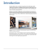
Introduction The Planar UltraLux Series is a family of large format 70" and 80" displays which combine style and aesthetics with high performance display technology. From its sleek design to lasting 24 x 7 reliability, the Planar UltraLux is ideally suited for retail brand communications, advertising networks, conference rooms, wayfinding, and other commercial signage applications.
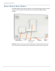
Planar UltraLux Series Features Planar UltraLux Series Features The Planar UltraLux Series delivers superior 24/7 visual performance shown in a lower total cost of ownership (TCO) compared to other large-format digital signage displays. Integrated media player compartment Cable box Control module/redundant power supply Kickstand stop bracket Mounting bracket Caution: AC power cord needs to be away from the three component boxes shown here.
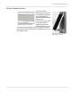
Planar UltraLux Series Features UltraLux Mounting System The Planar Profile™ Mounting System allows for simplified installation. The Profile Mounting System includes two wall brackets and incorporates a kick-stand feature that tilts the display away from the Wall mount brackets - landscape wall for easy access to the electronics. Eliminating the need to completely remove the display from the wall reduces complexity and service time by up to 70%.
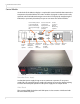
Planar UltraLux Series Features Control Module On the back of the UltraLux display is a replaceable control module that contains the components described below. The entire module is designed so that it can be easily replaced in the field without having to remove the LCD display. By simply using the kickstand, as previously described, one person can access the control module. Leave in “Run” position to ensure backlight power is reduced by 50% if a power supply fails.
Planar UltraLux Series Features Power Board This is used to generate the required voltages needed to run the control module. Integrated Media Player Storage Planar UltraLux displays incorporate a 1U media player compartment enabling a fully-integrated digital signage display system that can power a 5V or 12V media player up to 3A on each supply.
Remote Control Remote Control All on-screen functions can be accessed using the remote control. Note that only the buttons highlighted below are applicable to the UltraLux Series panels. Turns on/off the AC power to the LCD module. Four arrow keys move the selector as shown: up, down, left or right. Mutes the audio. Press to access on-screen menus. Select this to choose a source. Also use as the Back button when navigating through menus.
IR Sensor IR Sensor The IR sensor is located inside the control module, which is in the rear of the LCD. In order to reach the IR sensor signal using the remote control, you will need to aim the remote from the side of the LCD module. See the following drawing for the general angles from which the remote control will reach the IR sensor signal.
Safety Information Safety Information This display was designed with safety in mind. If you don’t heed the safety warnings and cautions, you could get hurt. The safety warnings are on stickers in various places in and on the display. Important Safety Instructions 1 Read these instructions. 2 Keep these instructions. 3 Heed all warnings. 4 Follow all instructions. 5 Do not use any of the Planar UltraLux Series products near water.
Safety Information 14 You must follow all National Electrical Code regulations. In addition, be aware of local codes and ordinances when installing your system. 15 Refer all servicing to qualified service personnel.
Safety Information European Union Disposal Information English ■ Disposal of old Electrical & Electronic Equipment (Applicable throughout the European Union and other European countries with separate collection programs) Français ■ Mise au rebut des équipements électriques et électroniques usagés (Valable dans l’ensemble de l’Union Européenne ainsi que dans les pays européens disposant de programmes distincts de collecte des déchets) This symbol found on your product or on its packaging, indicates that t
Recommended Usage Recommended Usage The Lux series uses commercial grade LCD panels, and is designed for 24/7 operation. With certain static images and extreme conditions, a slight amount of temporary image retention may occur. To minimize this possibility, it is recommended that either static images be changed occasionally (for example to a different screen layout, or a black screen), or that a periodic display shutdown be programmed using RS232 commands or the UltraLux Remote Monitoring software.
Recommended Usage Normal Use Thermal Guidelines Normal use of the LCD module and power supply module are defined as operating in the open air to prevent heat buildup, and without direct or indirect heat sources such as lighting fixtures, heating ducts, or direct sunlight that can cause the modules to experience high operating temperatures. For all modules, do not block fans or ventilation openings.
Installing the Planar UltraLux Series This section explains how to install a Planar UltraLux display. We suggest that you read this entire section before you attempt an installation. Before You Begin Make sure you have all the items in the following lists before you begin unpacking and installing your Planar UltraLux Series. Tools/Equipment List Depending on your installation, you may need one or more of the following items. Note that depending on the size of the display, this list may be different.
Powering On/Off Displays Powering On/Off Displays There are several ways to turn the UltraLux Series on or off: • • • • 14 Use the on/off switch on the AC power inlet Use the power button on the remote control Use the RS232 commands Use the UltraLux Remote Monitoring embedded software via Ethernet Planar UltraLux Series Installation Guide
Unpacking and Checking Accessories Unpacking and Checking Accessories The UltraLux includes the LCD and an accessory kit. A wall mount kit can be purchased separately. Note: Screws should be no less than 1/4” in diameter. You will need a minimum of eight screws for the top mounting bracket and a minimum of four for the bottom kickstand bracket. Additional screws may be needed depending on your installation. Accessory Kit Part Description AC power cord 90 degree low profile power cord.
Unpacking and Checking Accessories Optional Planar-Supplied Accessories The following optional items are available to order as part of your installation: • Pedestal • Planar ContentSmartTM Media Player • ProfileTM Wall Mount 16 Planar UltraLux Series Installation Guide
Wall Mounting LCD Using Planar Profile Mount Before installation, keep the following points in mind: • These displays are heavy. Make sure that you have adequate studs to support the weight of each display if installing on a wall. • The UltraLux must be installed on a flat surface. • Use supplied UltraLux mounting template for top and bottom bracket installation. • The wall mounts for a landscape and portrait installation look different. However, the process to install them is exactly the same.
Installing an LCD Module on a Wall Using Planar Profile Mount 18 2 Using the Planar provided mounting template, line up the top hole in the template with the center point on the wall. This is where the center of the top bracket will be hung. 3 Screw in the appropriate hardware in the top middle hole of the template. 4 Let the template hang vertically, as the bottom hole in the template determines where the bottom bracket will be installed.
Installing an LCD Module on a Wall Using Planar Profile Mount 7 Line up the middle hole of the top wall bracket with the screw hole drilled from the template. Note: This picture shows brackets for a landscape installation. 8 Tighten the screw into the bracket. 9 Use a level to make sure the bracket is level. 10 Then install additional screws as needed. 11 Install the center screw in the bottom bracket and repeat steps 9-10.
Installing an LCD Module on a Wall Using Planar Profile Mount 12 Using two people, carefully hang the back LCD onto the top wall mount bracket using the square brackets on the back of the display. Caution: Be sure that these are securely hung, as the top of the wall bracket will hold most of the weight of the display. Note: The pictures above show a landscape installation.
Installing an LCD Module on a Wall Using Planar Profile Mount 13 On the bottom wall bracket, there is a latch pin. Once you have hung the LCD on the top wall bracket, align the latch pin with the slot on the kickstand stop bracket located on the back of the LCD. Kickstand stop bracket Bottom wall mount bracket Captive screw Latch pin 14 Finger tighten the captive screw on the bottom to secure the latch pin.
Installing an LCD Module on a Wall Using Planar Profile Mount Portrait Installation 1 Find the top alignment hole on which the display will be hung by using the alignment bar shipped with your display. Then mark that spot on the wall with a pencil. Determine the desired position of the display on the wall. Place mark of centerline 1.5” below the top edge of the display. 2 22 Place a mark on the centerline of the display, 1.5” below the top edge.
Installing an LCD Module on a Wall Using Planar Profile Mount 3 With the alignment bar vertical (shipped with alignment brackets), locate the lower alignment hole and then mark that spot with a pencil. Hang alignment bar from top hole. Bottom of alignment bar for Portrait installation 4 Hang the alignment bar from the top hole that you marked in the first step. Using a 1/4” screw to lightly secure the alignment bar.
Installing an LCD Module on a Wall Using Planar Profile Mount 5 To install the upper wall mount, hold the mount in place using the centering hole in the middle of the mount and use a 1/4” lag screw to secure it. Centering hole 24 6 Level the wall mount before continuing. 7 Install the remaining lag screws - eight are recommended but more can be used as necessary.
Installing an LCD Module on a Wall Using Planar Profile Mount 8 To install the lower wall mount (kickstand), hold it in place using the centering hole and a 1/4” lag screw (use the lower alignment hole that was marked in step 3. Centering hole 9 Install the remaining lag screws - four are recommended - with two on each side. 10 Prepare the lower mount (kickstand) for installing the display. Loosen captive. Latch 11 Loosen the captive screw so the latch can rotate.
Installing an LCD Module on a Wall Using Planar Profile Mount 12 Using two people, carefully hang the back LCD onto the top wall mount bracket using the square brackets on the back of the display. Note: This example shows a Landscape installation. The Portrait installation is similar. Caution: Be sure that these are securely hung, as the top of the wall bracket will hold most of the weight of the display.
Installing an LCD Module on a Wall Using Planar Profile Mount 13 On the bottom wall bracket, there is a latch pin. Once you have hung the LCD on the top wall bracket, align the latch pin with the slot on the kickstand stop bracket located on the back of the LCD. Kickstand stop bracket Bottom wall mount bracket Captive screw Latch pin 14 Finger tighten the captive screw on the bottom to secure the latch pin.
Installing an LCD Module on a Wall Using Planar Profile Mount Installing Cables The only cable you will need to install is the AC power cord into the back of the control module. Depending on your setup, you may need additional cables for media player integration, as well as for sending RS232 commands. Below are examples of cable connections between the control module and a media player.
USB and Power Hook-Up Touchscreen Setup USB and Power Hook-Up 1 Using the display service kickstand, swing out the display. If you are only using the mount, make sure you have at least 1” clearance to connect the USB and power. 2 Plug in the 5V, 4A Power supply connector to the touchscreen power connector. Power USB Note: USB and Power connection to the touchscreen. 3 Connect the 5V line cord to the power adapter.
Touchscreen MultiTouch Driver Installation Touchscreen MultiTouch Driver Installation 1 With the PC on, plug in the USB memory stick to the USB drive. 2 Locate and open the USB drive. 3 Double-click on the “mt_driver_kitV4.1212RC2” to install the driver. 4 Follow installation prompts until driver installation is complete. Once driver installation is complete, the touchscreen is ready for use.
Uninstalling the MultiTouch Driver Options • Default settings on options have the following programs enabled: Tuio Support, Flash Tuio Support, Handwriting Optimization, Enable Windows Native Touch, Enable Mouse/Keyboard Simulation, and Launch When Windows Starts Up. • Flexible Scan Rate is at a default setting. Uninstalling the MultiTouch Driver 1 On the PC, select the Start menu, All Programs and then PQLabs Software. 2 Click on the MultiTouch Driver. 3 Select the Uninstall option.
Uninstalling the MultiTouch Driver 32 Planar UltraLux Series Installation Guide
External Control and Monitoring In addition to using the UltraLux remote control and display, there are other methods of controlling the UltraLux externally: • Using a serial (RS232) link to send commands and to receive responses to those commands. • Using SNMP (Simple Network Management Protocol) to monitor the device status. • Using Remote Monitoring software via a web browser.
RS232 Communication RS232 Communication RS232 control is not necessary for operation, but is a convenient way to control displays from a computer at a distance. If your installation will not use RS232 control, skip this section. Most things you can do with the remote, you can do with RS232 commands. Plus, you can send inquiries to the displays and find out the current settings and values. RS232 connections are made with standard straight-through cables.
RS232 Commands RS232 Commands The following table provides the most common RS232 commands that can be used.
RS232 Commands Item Command Value in Hex Command Result 14 Set Color Temp to "9300K" 08 22 04 00 00 00 06 CC Color temp set to commanded value 15 Set Color Temp to "user" 08 22 04 00 00 00 07 CB Color temp set to commanded value 16 Get Color Temp 04 21 0B D0 17 Set Red to "X" (0 to 100) Set to 50: 08 22 0E 00 00 00 32 96 Returns "Color Temp = value" where value is 2 for 4200K, 3 for 5000K, 4 for 6500K, 5 for 7500K, 6 for 9300K Red set to commanded value (impacts only user color mode) 18
SNMP Monitoring SNMP Monitoring The current settings and status of UltraLux units can be remotely monitored using SNMP (Simple Network Management Protocol), if the SNMP option is enabled through the web browser settings. The MIB (Management Information Base) used for all Planar display products is available by electronic distribution in the file PLANARDISPLAY-MIB.txt. The table below shows the objects that can be monitored – all Planar SNMP objects are read-only, and no traps are used.
Sending RS232 Commands Via UDP Sending RS232 Commands Via UDP The UDP port 57 accepts the same command sets as RS232. It is convenient for IP control applications and can be tested with a UDP terminal program such as the Hercules SETUP utility available from www.HW-group.com Note: Ensure that the Enable ASCII command service (UDP port 57) box is checked on the Access Control page of the Remote Monitoring software.
Using WallNet Assistant Using WallNet Assistant WallNet Assistant is a software program that finds Planar hardware on a network. This will help you find the IP address needed to access the Remote Monitoring functions. 1 WallNet Assistant is distributed as Planar_WallNet_Assistant_(version).zip. Extract all files to a new folder in your "Program Files" folder (or another convenient location). 2 Double-click "WallNet Assistant.exe" to launch Planar WallNet Assistant.
Using WallNet Assistant 3 When WallNet Assistant starts, it looks for all Planar device servers on the network and lists them in the window. • Each Planar device found on the local network is listed with its name, IP address, date and time. • New device servers just out of the box are listed with default names. The date and time shown are from the device’s own clock. Both of these can be changed later.
Using WallNet Assistant 5 When your browser connects to a Planar network device, you should see a page similar to the following.
Using WallNet Assistant Route Add Command If you are trying to connect to a Planar device server that you believe is at the factory default IP address, and your computer is not on the 192.168.12.0 network, then you can use the route add command to establish a connection from your computer to that device server. This method only works if your computer and the Planar device are connected to the same network switch or hub.
Planar UltraLux Remote Monitoring Planar UltraLux Remote Monitoring Planar UltraLux Remote Monitoring is software that displays information about the LCD display via a web browser. It is used primarily for monitoring, reporting and some control (for example, manually powering the displays on and off). Remote Monitoring Home This is the first page you will see when you open the Planar UltraLux Remote Monitoring software. Launch a web browser.
Planar UltraLux Remote Monitoring Unit Status The Unit Status page shows a list of the different system settings for the LCD. It also shows whether or not the two power supplies contained in the control module are on or off.
Planar UltraLux Remote Monitoring Display Control The Display Control page contains two sub-pages: Power On/Off and Custom Commands Setup. These are described in the following pages.
Planar UltraLux Remote Monitoring Power On/Off Power On/Off buttons control the backlight power, not the AC power. You cannot control AC power through Planar UltraLux Remote Monitoring. This section has four options for which you can schedule an automatic power on/off. The options are: no automatic power on/off, same daily schedule, Monday-Friday same schedule and weekends off. Or each day has its own schedule. You can only select one of the schedule types. The default is No automatic power on/off.
Planar UltraLux Remote Monitoring Custom Commands Setup The Custom Commands Setup page allows you to establish what the ten Custom Command buttons will do. 1 Type a label for the button in Button 1 Text. 2 In ASCII Command(s), enter a binary protocol such as hex commands. An example is shown above. 3 Click Test button 1 commands to send the commands immediately. You will see an output page showing the commands sent and replies received (if any).
Planar UltraLux Remote Monitoring Admin Setup The Admin Setup page contains three sub-pages: Network Setup, Time and Date, Access Control and Software Update. These are described in the following pages.
Planar UltraLux Remote Monitoring Network Setup This page allows you to configure network settings and whether or not you use DHCP. 1 In the Hostname box it now says Planar. Change this name to something more appropriate. This will be the name for this particular server. The hostname is limited to 16 characters: alphanumeric, dash, or underscore only. 2 If you want to enter a domain name for server name lookups, type it in the Domain name box.
Planar UltraLux Remote Monitoring b You do no need to fill in anything under the Static (non-DHCP) Network Settings section. However, if you do, these settings will be used in the event that the DHCP attempts to time out. c Go to step 6. 5 Under the DHCP section, choose No, use static settings. a In the Static (non-DHCP) Network Settings section, enter the IP address given to you by the network administrator. b Enter the Network mask, DNS server(s), and Gateway as instructed by the network administrator.
Planar UltraLux Remote Monitoring Date and Time Use this page to change date and time information as needed. 1 Set the date and time manually in the box under the Manual Date and Time section. The date format is very exact. Fill in the current date and time using exactly the format shown on the page. Click Set date and time. 2 If you want to have the server periodically check the time from a network source, fill in the NTP server name or address, and poll interval in the Date and Time Server section.
Planar UltraLux Remote Monitoring Access Control The Access Control page allows you to set parameters needed to access the web, the Remote Monitoring network, RS232 commands, as well as select the correct baud rate.
Planar UltraLux Remote Monitoring Software Setup This page allows you to upload the latest UltraLux Remote Monitoring software. You can also reset all of your settings to the factory defaults, as well as choose the web page link that is associated with the Planar logo in the top right corner of the page. 1 Click the Choose File button to locate the latest UltraLux software that you downloaded from Planar’s website. Note: Make sure the software is downloaded to a local drive.
Planar UltraLux Remote Monitoring 4 When you click Reset ALL to Factory Default, you receive the Confirm Factory Reset page. Click OK, Reset to Factory Defaults and Reboot if you are sure you want to reset ALL settings to the factory default. 5 The top of each page shows the Planar logo, which is a link to http://www.planar.com. You can change this link to refer to any URL that you find useful by typing it into the Product ID Link box. 6 To make this link live, click Change Product ID Link.
On-Screen Display Menus On-Screen Display Menus On-screen menus can be accessed using the remote control. These menus allow you to adjust image brightness, contrast, sharpness, color, sound, and various System Settings. Below are pictures of the menus and a menu tree that shows the options on each menu.
On-Screen Display Menus Image Brightness Contrast Sharpness auto Color Color temp 4200K 5000K 6500K 7500K 9300K user Full color srgb Hue Saturation 56 Planar UltraLux Series Installation Guide Red Green Blue xvycc
On-Screen Display Menus Display Menu Display Auto adjust phase clock Display position Move position V Move position H Planar UltraLux Series Installation Guide 57
On-Screen Display Menus Sound Menu Sound volume mute 58 Planar UltraLux Series Installation Guide
On-Screen Display Menus System Menu Planar UltraLux Series Installation Guide 59
On-Screen Display Menus system Input Display Port VGA DVI/HDMI Osd Settings Timer 3 sec 6 sec 12 sec Rotation 0° 90° 180° 270° Position Transparency Language English Espanol Deutsch French Reset 60 Planar UltraLux Series Installation Guide
Specifications Screen Active Area Size Power Consumption (typical) Dimensions (including mount) Bezel Width Weight Mounting UltraLux 70” UltraLux 80” UltraLux 70” Touch UltraLux 80” Touch 70 inch 80 inch 70 inch 80 inch 300W 350W 300W 350W 62.2" x 36.2" x 3.0" 72.2" x 41.7" x 2.8" 62.5” x 36.4” x 3.4” 73.5” x 43.1” x 3.4” (1581mm x 920mm x 77mm) (1835mm x 1060mm x 71mm) (1588mm x 926mm x 85mm) (1868mm x 1096mm x 85mm) 1.1” (27mm) 1.
Signal Compatibility Signal Compatibility The UltraLux Series supports the following factory preset modes: 62 Mode Resolution Refresh Rate Horizontal Frequency Pixel Frequency VGA 640 x 480 60 Hz 31.5 kHz 25.157 MHz SVGA 800 x 600 56 Hz 35.2 kHz 36 MHz SVGA 800 x 600 60 Hz 37.9 kHz 40 MHz XGA 1024 x 768 60 Hz 48.4 kHz 65 MHz WXGA 1280 x 720 60 Hz 45 kHz 74.
UltraLux Dimensions Note: All Drawings for the UltraLux Series have the same dimensions in Portrait mode. Simply flip the drawings around to see the correct dimensions.
” LCD Module Dimensions 70” LCD Rear View - Landscape 0 0RXQW 3RLQWV PP [ PP &$%/( &29(5 $1' , 2 /2&$7,21 0(',$ 3/$<(5 &203$570(17 64 Planar UltraLux Series Installation Guide
70” LCD Module Dimensions 70” LCD Side View - Landscape 3DQHO 3URILOH 2YHUDOO Planar UltraLux Series Installation Guide 65
70” LCD Module Dimensions 70” Panel Mounting Dimensions LQ PP 0 9(6$ 0RXQW LQ PP 7R HGJH RI SDQHO LQ PP 7R HGJH RI SDQHO [ 3ODQDU 0RXQW %UDFNHW LQ PP 7R HGJH RI SDQHO LQ PP 7R HGJH RI SDQHO LQ PP 7R HGJH RI SDQHO LQ PP 7R HGJH RI SDQHO 3RZHU %R[ &RPSDUWPHQW 0HGLD 3OD\HU &RPSDUWPHQW LQ PP 7R HGJH RI SDQHO LQ PP 0 9(6$ 0RXQW &DEOH &RYHU DQG , 2 /RFDWLRQ LQ PP 7R HGJH RI SDQHO LQ PP 7R HGJH RI SDQHO LQ PP 7R HGJH RI
70” LCD Module Dimensions 70” Wall Mount Kit - Front Landscape 7<3 ; ',63/$< 287/,1( )5217 9,(: 70” Wall Mount Kit - Side Landscape ',63/$< 287/,1( '( 9,(: Plan
70” LCD Module Dimensions 70” Wall Mount Kit - Front Portrait 7<3 7<3 ; ',63/$< 287/,1( 68 Planar UltraLux Series Installation Guide
70” LCD Module Dimensions 70” Wall Mount Kit - Side Portrait ',63/$< 287/,1( :$// 25 02817,1* 685)$&( ,'( 9,(: Planar UltraLux Series Installation Guide 69
70” LCD Module Dimensions 70” LCD Touch View - Front LQ PP %H]HO LQ PP LQ PP 70 Planar UltraLux Series Installation Guide LQ PP %H]HO
70” LCD Module Dimensions 70” LCD Touch View - Rear LQ PP 2YHUKDQJ RQ WRS DQG ERWWRP DO GHSWK RI XQLW LQ PP 2YHUKDQJ RQ OHIW DQG ULJKW VLGH (OHF &RQWURO 0RGXOH $ &DEOH &RYHU 0HGLD 3OD\HU &RPSDUWPHQW 3/$1$5 6<67( 1: &203 Planar UltraLux Series Installation Guide 71
70” LCD Module Dimensions 70” LCD Touch View - Side LQ PP 7RWDO GHSWK RI XQLW 2YHUKDQJ RQ O 72 Planar UltraLux Series Installation Guide %
80” LCD Module Dimensions 80” LCD Module Dimensions 80” LCD Front View - Landscape Planar UltraLux Series Installation Guide 73
” LCD Module Dimensions 80” LCD Rear View - Landscape 0 0RXQW 3RLQWV PP [ PP &$%/( &29(5 $1' , 2 /2&$7,21 0(',$ 3/$<(5 &203$570(17 74 Planar UltraLux Series Installation Guide
80” LCD Module Dimensions 80” LCD Side View - Landscape 3DQHO 3URILOH 2YHUDOO Planar UltraLux Series Installation Guide 75
80” LCD Module Dimensions 80” Panel Mounting Dimensions LQ PP 0 9(6$ 0RXQW [ 3ODQDU 0RXQW %UDFNHW LQ PP 7R HGJH RI SDQHO LQ PP 7R HGJH RI SDQHO LQ PP 7R HGJH RI SDQHO LQ PP 7R HGJH RI SDQHO LQ PP 7R HGJH RI SDQHO LQ PP 7R HGJH RI SDQHO 3RZHU %R[ &RPSDUWPHQW 0HGLD 3OD\HU &RPSDUWPHQW LQ PP 0 9(6$ 0RXQW &DEOH &RYHU DQG , 2 /RFDWLRQ LQ PP 7R HGJH RI SDQHO LQ PP 7R HGJH RI SDQHO LQ PP 7R HGJH RI SDQHO 76 Planar UltraLux Series I
80” LCD Module Dimensions 80” Wall Mount Kit - Front Landscape 7<3 7<3 7<3 ',6 28 ; ',63/$< 287/,1( ; )5217 9,(: 80” Wall Mount Kit - Side Landscape
80” LCD Module Dimensions 80” Wall Mount Kit - Front Portrait 7<3 7<3 ',63/ 287/ ; ',63/$< 287/,1( 78 ; Planar UltraLux Series Installation Guide 6,'(
80” LCD Module Dimensions 80” Wall Mount Kit - Side Portrait ',63/$< 287/,1( :$// 25 02817,1* 685)$&( 6,'( 9,(: Planar UltraLux Series Installation Guide 79
80” LCD Module Dimensions 80” LCD Touch View - Front LQ PP %H]HO '(7$,/ % 6&$/( LQ PP LQ PP %H]HO 80 Planar UltraLux Series Installation Guide LQ PP
80” LCD Module Dimensions 80” LCD Touch View - Rear [ UHPRYDEOH FRUQHU EUDFNHW IRU 7RXFK )UDPH LQVWDOODWLRQ VHUYLFDELOLW\ LQ PP 2YHUKDQJ RQ WRS DQG ERWWRP HGJH LQ PP 2YHUKDQJ RQ OHIW DQG ULJKW HGJH (OHF &RQWURO 0RGXOH $ &DEOH &RYHU 0HGLD 3OD\HU &RPSDUWPHQW Planar UltraLux Series Installation Guide 3/$1$5 6<67(06 1: &203721 %($9(5721 25 81
80” LCD Module Dimensions 80” LCD Touch View - Side LQ PP 7RWDO GHSWK RI GLVSOD\ ZLWK WRXFK 6ROXWLRQ 82 Planar UltraLux Series Installation Guide %
Media Compartment Player Dimensions Media Compartment Player Dimensions LQ PP LQ PP '(7$,/ $ 0HGLD 3OD\HU &RPSDUWPHQW 0D[ 8 KHLJKW 6KRZQ ZLWK FRYHU UHPRYHG $ 9(6$ PRXQW [ 0HGLD 3OD\HU &RPSDUWPHQW , 2 /RFDWLRQ Planar UltraLux Series Installation Guide 3/$ %( 83
Media Compartment Player Dimensions 84 Planar UltraLux Series Installation Guide
UltraLux Pedestals The following picture shows examples of the 70” and 80” UltraLux pedestals. Installing the UltraLux on the Pedestal Mount The pedestal mount comes fully assembled, single or double-sided, depending on your configuration. If you have ordered a single-sided pedestal mount, a back panel will also be installed. Caution: When installing the pedestal mount, you must ensure that it is attached to a structure that safely supports UltraLux display.
Installing the UltraLux on the Pedestal Mount 86 5 Route all cabling through the bottom of the pedestal mount or through both sides of the mount. If you run cables through the sides of the mount, you can punch out holes and install grommets through which to run the cables. 6 Install the UltraLux on the Planar Profile Mount that is already attached to the pedestal mount. See "Installing an LCD Module on a Wall Using Planar Profile Mount" on page 17 for more information.
70” UltraLux Pedestal Dimensions 70” UltraLux Pedestal Dimensions 70” UltraLux Pedestal - Front LQ PP LQ PP LQ PP &HQWHU RI GLVSOD\ LQ PP %RWWRP RI GLVSOD\ Planar UltraLux Series Installation Guide 87
70” UltraLux Pedestal Dimensions 70” UltraLux Pedestal - Top and Side LQ PP LQ PP LQ PP [ 5HPRYDEOH %DVH &RYHU IRU ,QVWDOO DQG &DEOH 0DQDJHPHQW ,QVWDOOHG 3RVLWLRQ 88 Planar UltraLux Series Installation Guide
70” UltraLux Pedestal Dimensions 70” UltraLux Pedestal - Anchor Dimensions +DUGZDUH WR DQFKRU SHGHVWDO 6(&7,21 $ $ 2SHQ WR WKH IORRU IRU FDEOH PDQDJHPHQW LQ PP LQ PP LQ PP LQ PP LQ PP $ LQ PP LQ PP $ 2SHQ WR WKH IORRU IRU FDEOH PDQDJHPHQW Planar UltraLux Series Installation Guide 89
80” UltraLux Pedestal Dimensions 80” UltraLux Pedestal Dimensions 80” UltraLux Pedestal - Front LQ PP LQ PP LQ PP &HQWHU RI GLVSOD\ LQ PP %RWWRP RI GLVSOD\ 90 Planar UltraLux Series Installation Guide
80” UltraLux Pedestal Dimensions 80” UltraLux Pedestal - Top and Side LQ PP LQ PP LQ PP [ 5HPRYDEOH %DVH &RYHU IRU ,QVWDOO DQG &DEOH 0DQDJHPHQW ,QVWDOOHG 3RVLWLRQ Planar UltraLux Series Installation Guide 91
80” UltraLux Pedestal Dimensions 80” UltraLux Pedestal - Anchor Dimensions +DUGZDUH WR DQFKRU SHGHVWDO 2SHQ WR WKH IORRU IRU FDEOH PDQDJHPHQW 6(&7,21 $ $ LQ PP LQ PP LQ PP LQ PP LQ PP $ LQ PP LQ PP $ 2SHQ WR WKH IORRU IRU FDEOH PDQDJHPHQW 92 Planar UltraLux Series Installation Guide
Accessing Planar’s Technical Support Website 1 Go to http://partners.planarcontrolroom.com 2 Once you enter your login and password, you can access downloadable utility software, new firmware, user manuals, and service manuals. Downloading Additional Documentation and Software Some of the other documents and software updates for the for the UltraLux Series are or will be available from the Technical Support Department website. Downloading Utility Software 1 Go to http://partners.planarcontrolroom.com.
Field Replaceable Units (FRUs) 94 Planar UltraLux Series Installation Guide
Regulatory Information Manufacturer's Name: Manufacturer's Address: Planar Systems, Inc. 1195 NW Compton Drive Beaverton, OR 97006 Declares that the products Model Numbers: Planar UltraLux Series 70”/80” large format LCDs.
Customer Support Contact Information and Hours of Operation Customer Support Information 24/7 Online Technical Support is available at http://www.planar.
Index Operation Numbers C 70" dimensions pedestal anchor, 89 70" display dimensions, 63 70" wall mount kit dimensions, 67 80" dimensions pedestal anchor, 92 80" display dimensions, 73 80" wall mount kit dimensions, 77 certifications, 95 cleaning the display screen, 13 commands creating custom in Remote Monitoring, 47 conformity information, 95 Control, 4 control module, 4 controlling display via Remote Monitoring, 45 custom commands in Remote Monitoring, 47 customer support hours of operation, 96 phone n
Index E equipment list, 13 european union disposal information, 10 F menus, 55 Display menu, 57 Image menu, 55 Sound menu, 58 System menu, 59 mounting system, 3 N features of UltraLux, 2 hours of operation for customer support, 96 network access controlling in Remote Monitoring, 52 network setup in Remote Monitoring, 49 normal use thermal guidelines, 12 I O Image menu, 55 installation before you build, 17 checklist, 15 of LCD, 13, 17 planning, 13 preparing your location, 14 introduction, 1 IR sens
Index Remote Monitoring, 43 Access Control, 52 Admin Setup, 48 Custom Commands Setup, 47 Date and Time, 51 Display Control, 45 Home, 43 Network Setup, 49 power on/off, 46 rebooting the system, 54 Software Setup, 53 Unit Status, 44 RS232 commands, 35 control, 5 U UltraLux Series features, 2 integrated media player, 5 IR sensor, 7 LED technology, 5 mounting system, 3 product architecture, 6 remote control, 6 unit status for Remote Monitoring, 44 unpacking accessories, 15 usage information, 11 W S wall mo
Index iv Planar UltraLux Series Installation Guide