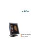
Dome E2c Display User’s Guide
© 2006 Planar Systems, Inc. All rights reserved. Information in this document has been carefully checked for accuracy; however, no guarantee is given to the correctness of the contents. This document is subject to change without notice. Planar provides this information as reference only. Reference to other vendors’ product does not imply any recommendation or endorsement. This document contains proprietary information protected by copyright.
Contents Product Information About the Display iv 1 Installing the Display Appendix Index 5 10 19 Regulatory Compliance Standard Warranty 20 25 iii
Product Information The design of the Dome E2c digital display takes into account every known measure to ensure your personal safety. Improper use of the display can result in electric shock, fire, or damage to the display. Read all instructions before setting up the display. Classification: Shock Protection: Class I. Degree of Protection Against Electric Shock: No applied part. Degree of Protection Against Harmful Ingress of Water: Ordinary equipment (IPX0).
Symbol explanations DISPOSAL. Do not use household or municipal waste collection services for disposal of electrical and electronic equipment. EU countries require the use of separate recycling collection services. CAUTION. Read the accompanying text carefully, for proper operation and maintenance of the display system. DANGEROUS VOLTAGE. Important precautions about electric shock. Read the accompanying text carefully, to prevent damage to components of the display system and for your safety.
Safety precautions External equipment intended for connection to signal input, signal output, or other connectors, must comply with the relevant IEC standard (EN/IEC 60601-1 series for medical electrical equipment). In addition, all such combinations (systems) must comply with the standard IEC 60601-1-1, Safety requirements for medical electrical systems. Equipment not complying to IEC 60601 must be kept outside the patient environment, as defined in the standard as at least 1.
Unpacking and handling tips The Dome E2c display is a precision instrument that requires proper care to maintain product operation and adherence to specification. Unpack the display and components carefully, then set up and handle the unit properly to avoid damage to the LCD panel. • Use both hands to grasp the display case when lifting it from the shipping carton, but avoid touching the screen. • Do not apply pressure to the screen or touch the screen with bare fingers or objects.
Cleaning the display Observe the following guidelines to maintain the display and the LCD screen. • Use a clean, lint-free, absorbent cotton cloth to clear off any residual glue from removal of the protective film or to remove surface dust. Apply light pressure to remove the dust. • Dampen a clean cloth with a small amount of isopropyl alcohol to remove glue or dust if the screen is still not clean. Do not saturate the cloth; otherwise, alcohol may seep into the display case and collect in the enclosure.
Shipping/storing the display Keep the display in its shipping container until installation. Return the display to its original container whenever you need to store the unit, move it to another location, or return it for repair. The packaging supplied by the manufacturer protects the display while it is in transit. See environment specifications for more information. Before returning the display to the container, do the following: 1 Swivel the display panel in landscape mode.
AMLCD panel mounted on desk stand Display controller DVI cable DC power adapter Quick reference Also included: Composite video, S-video, and VGA cables Power cords Display driver and calibration software
About the Display The Dome E2c display system offers a 541-mm (21.3-in) color UXGA 1200x1600 AMLCD unit with a luminance output of 500 nits minimum. The display connects directly to a controller board via a Digital Visual Interface 1.0 interface. With AMLCD modules delivering 2-megapixel resolutions, the display’s thin film transistors operate in a transmissive-type display using an integrated cold cathode fluorescent tube (CCFT) high-bright backlight system.
Display Components Review this illustration of the back panel to identify controls and ports on the display unit. 1 2 3 4 5 6 7 Legend 1 2 3 4 Reset. Restores the display configuration to default. LED. Shows display status. DIN 8-pin connector. Drives power to the display. S-Video, separate video analog input port. Requires a 4-pin mini-DIN connector. 5 C-Video, composite video analog input port. Requires an RCA or phono connector. 6 DVI. DVI-I video input port.
Display Positions You can adjust the tilt, height, viewing angle, and orientation of the display to maintain an ergonomic and comfortable viewing position. Make sure that your eyes are level with the top of the display cabinet so that you look downward to read the screen contents. Select a suitable workspace for the display. You need a stable, level, and clean surface near a wall outlet.
Desk Stand Features Unfasten the stand lock to adjust display height. Remove the stand cover to thread the power cord and DVI cable connections to the display. To activate the USB hub function, the display must be connected to a USB-compliant computer or another hub with a USB cable. Even if the display is in power-saving mode, the USB devices function when connected to the USB ports of the display. Stand height lock Move the stand lock lever to the left to adjust the height of the display.
Installing the Display Before you install the display controller, remove any existing graphics card and its driver from your system. Also disable any onboard graphics capability on the motherboard. Warning • In locations where 240V outlets are used, connect the Dome E2c display only to a center-tapped, 240V, single-phase supply (only for Canada and the United States). • Turn off the computer before installations.
Install the Display Controller Before you install the AX1 display controller, make sure your display system will be set up in a well-ventilated location with an adequate amount of space. Excessive heat cannot dissipate when display vents are blocked. Turn off your computer and peripherals. Disconnect all the cables. Leave the power cord plugged into the grounded outlet. If you are installing multiple display controllers, install all boards before you install the display driver.
Connect the Video and Power Cables Use only the power adapter (Ault MW122KA1223F52), power cord, and the video cable shipped with the Dome E2c display. To connect the cables 1 Plug one end of the DVI cable into the DVI port on the connector plate. Secure the connection. 2 Plug the power cord into the power input port on the plate. 3 Plug the other end of the DVI cable into the video port on the installed display controller. Secure the connection.
Install the Display Driver Upon restarting your computer system, you must log on with administrator privileges. On Windows 2000 systems, Service Pack 4 or higher must be installed. To install the driver 1 Start the system. Click Cancel on the Found New Hardware Wizard. Click No when the system prompts you restart the computer. 2 Insert the driver installation CD and run setup.exe. 3 Click Next. 4 Click Yes to the license agreement. The installation starts.
Adjust Display Properties Use the Display Properties dialog to make changes to the video settings or to set up a dual-display configuration. To set the display orientation 1 Right-click the desktop and select Properties > Settings. 2 Select the monitor that you want to change. Then click Advanced. 3 Click the Monitor tab. Make sure that the check box for Hide modes that this monitor cannot display is empty (unchecked). 4 Click the Rotation tab. > Check Standard landscape for landscape mode.
Appendix Troubleshooting Dome E2c Specification Video Modes Video Timing Connector Ports LED Status Lights Component Removal Power Management 10 | Dome E2c Display
Troubleshooting Problem Possible Cause Solution No image appears on the screen Computer is not powered on. Turn on computer. Power cord is not securely connected. Tighten power cord connection and turn on computer. Video cable connected incorrectly. Make sure the first display of a dualheaded system or the only display of a single-headed system is connected to the Video 1 port on the display controller. A previous version of the display driver is still installed on the computer system.
Dome E2c Specification In locations where 240V outlets are used, connect the Dome E2c display only to a centertapped, 240V, single-phase supply (only for Canada and the United States). Category Characteristic Item Specification Screen Screen size diagonal 541 mm (21.3 in.
Power Supply CAUTION: Use only the power adapter supplied with the Dome E2c display unit; Ault MW122KA1223F52. Category Characteristic Item Specification Power input requirements Voltage selection Auto-ranging Voltage 100 – 240V AC Current 2.0 A Frequency 50 to 60 Hz Power output requirements Voltage 12 V DC ±5% Current 10.0 A (120 W) Physical Size 228.6 mm x 76.2 mm x 50.8 mm (9 in x 3 in x 2 in) Weight 1.3 kg (2.
Video Modes Resolutions expressed in pixels (W x H). Single desktop requires dual displays. Display Resolution Orientation Palette Bits per pixel Dome E2c 1200 x 1600 1600 x 1200 Portrait Landscape True color 32 Video Timing Standard Resolution Vertical Refresh (Hz) Horizontal Scan (Khz) IBM VGA IBM VGA IBM VGA 640x350 640x480 720x400 70 60 70 31.5 31.5 31.5 VESA VGA VESA VGA VESA VGA 640x480 640x480 640x480 72 75 85 37.9 37.5 43.
Connector Ports The video signal connector is a standard DVI connector, driving data to the display. Diagnosis requiring DICOM calibration with the Dome CXtra software can only be supported on the DVI-D interface. The Dome E2c display use an 8-pin DIN connector. The power input is 12V ±5% (120 W). See below for details of the DIN connector.
LED Indication Lights The LED indicator on the connector plate provides information on the display status.
Display Driver Removal Follow the appropriate procedure below to remove the AX1 driver from your system. To remove the AX1 driver 1 Close all applications that are running. 2 Navigate to the Control Panel and select Add/Remove Programs. 3 Select your current graphics card drivers and select Add/Remove. Follow the wizard to remove your current display drivers. 4 Restart your system.
Power Management You have two ways to lower energy usage when the Dome E2c display is idle: • Dome CXtra Backlight Saver service (preferred) • Screen Saver (set via Windows operating system) Activate the power saver when you anticipate periods of inactivity, such as at the end of the work day. Once activated, Backlight Saver (or Screen Saver) automatically turns the backlight off during the period of inactivity.
Index B L brightness, display 9 LED status lights 16 C M cleaning viii configuration, dual setup 9 connecting DVI cable 7 power cord 7 connector port 15 contents, package x managing power usage 18 D desk stand 4 DIN connector 15 display about 1 brightness 9 components 2 controller, installing 6 install 5 orientation 9 positions 3 properties, changing 9 disposal ix driver installing 8 removing 17 dual configuration 9 DVI cable, connecting 7 I information product iv technical 12 installing display co
Regulatory Compliance Canada, European Union, United States This display has been tested and found to comply with IEC/EN 60601-1 and IEC/EN 60601-1-2 standards, and is certified to meet medical standard C22.2 No. 601.1-M1990 (C US Mark).
The applicable safety standards for an MDD Class I display are IEC/EN 60601-1:1990 along with Amendments 1 and 2. To help the medical device designer evaluate the suitability of these displays, Planar has also conducted EMC testing to IEC 60601-1-2 as it can be applied. The display with its power supply alone does not represent a functional medical device. Hence, Planar configured a minimal operating system to exercise the display. The resulting data are made available to interested parties.
EU Declaration of Conformity for Medical Application A Declaration of Conformity has been filed for this product. For additional copies of the Declaration of Conformity document, contact Planar Systems.
U.S. FCC Compliance Statement This device complies with Part 15 of the FCC Rules. Operation is subject to the following two conditions: (1) This device may not cause harmful interference, and (2) this device must accept any interference received, including interference that may cause undesired operation. NOTE: This equipment has been tested and found to comply with the limits for a Class B digital device, pursuant to Part 15 of the FCC Rules.
Australian C-Tick Australian Communications Authority regulating product EMC compliance. China CCC China Compulsory Certification regulating safety and EMC. GB4943-2001 GB9254-1998 (Class A) CB17625.1-2003 Japan VCCI Voluntary Control Council for Interference by information technology equipment sold in Japan. Korea MIC Mark Ministry of Information and Communications.
Standard Warranty Summary • Standard 1-year “repair and return” warranty • A 2-year backlight warranty on color displays* • Typical repair turnaround time of 10 business days Standard Warranty Return Procedure As a Planar Standard Warranty customer, you must follow the procedure below if you have a non-functioning Dome EX display. The Planar customer service staff will attempt to correct any minor issues that may be causing the problem.
Summary Limitations and Exclusions of Dome Displays 1 Customer must provide original proof of purchase of the display system. 2 Warranty is void on any product with a defaced, modified, or removed serial number. 3 Warranty is void on any product with damage, deterioration, or malfunction resulting from the following: a) Accident, misuse, neglect, fire, water, lightning, or other acts of nature, unauthorized product modification, or failure to follow instructions supplied with the product.
Exclusion of Damages THE LIABILITY OF PLANAR IS LIMITED TO THE COST OF REPAIR OR REPLACEMENT OF THE PRODUCT. PLANAR SHALL NOT BE LIABLE FOR THE FOLLOWING: 1 DAMAGE TO OTHER PROPERTY CAUSED BY ANY DEFECTS IN THE PRODUCT, DAMAGES BASED UPON INCONVENIENCE, LOSS OF USE OF THE PRODUCT, LOSS OF TIME, LOSS OF PROFITS, LOSS OF BUSINESS OPPORTUNITY, LOSS OF GOODWILL, INTERFERENCE WITH BUSINESS RELATIONSHIPS, OR OTHER COMMERCIAL LOSS, EVEN IF ADVISED OF THEIR POSSIBILITY OF SUCH DAMAGES.
America Sales Planar Systems, Inc. 1195 NW Compton Drive Beaverton, OR 97006-1992 USA (503) 748-1100 phone (503) 748-1493 fax Medical Sales Planar Systems, Inc. 400 Fifth Avenue Waltham, MA 02451-8738 USA (781) 895-1155 phone (781) 895-1133 fax medicalsales@planar.com medicalsupport@planar.com www.planar.com Europe Sales European Representative Planar Systems, Inc. Olarinluoma 9, P. O. Box 46 FIN-02201 Espoo, Finland + 358 9 420 01 phone + 358 9 420 0200 fax vertrieb@planar.com medicalsupport@planar.