Operations Manual EL552.
Planar Systems, Inc. © 1998 Planar and “The Definition of Quality” are registered trademarks and ICE, ICEBrite, and ColorBrite are trademarks of Planar Systems, Inc. This document is subject to change without notice. Planar provides this information as reference only, and does not imply any recommendation or endorsement of other vendor’s products.
Contents EL552.256-Q2 Display................................................................................................................2 Features ................................................................................................................................................2 Installing and Handling ................................................................................................................2 Mounting EL Displays ......................................................
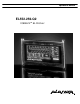
EL552.256-Q2 EL552.256-Q2 Display The EL552.256-Q2 thin film electroluminescent (EL) display is a highperformance alternative to lower resolution LCDs and VFDs and is the ideal solution in demanding applications where superior visual performance and environmental ruggedness are critical. The display consists of an EL glass panel and control electronics assembled into a space-saving, rugged package for easy mounting and a separate DC/DC converter with interconnecting cable. The EL552.
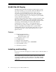
Mounting EL Displays Properly mounted, EL displays can withstand high shock loads as well as severe vibration found in demanding applications. However the glass panel used in an EL display will break if subjected to bending stresses, high impact, or excessive loads. CAUTION: To prevent injury in the event of glass breakage, the use of an impact resistant shield or a protective overlay should be used on the viewer side of the display. Stresses are often introduced when a display is mounted into a product.
EL552.256-Q2 Avoiding Burn-In As with other light emitting displays, displaying fixed patterns on the screen can cause burn-in, where luminance variations can be noticed. Use a screen saver or image inversion to avoid causing burn-in on the display. Specifications The EL panel is a matrix structure with column and row electrodes arranged in an X-Y formation. Light is emitted when an AC voltage of sufficient amplitude is applied at a row-column intersection.
VH is applied. The minimum and maximum specifications in Table 1 should be met, without exception, to ensure the long-term reliability of the display. The video inputs, shown in Table 2, pass from the video source to the display through the DC/DC converter. Table 1. Video Input Voltage Requirements Description Maximum input voltage Low-level input voltage High-level input voltage Low-level input current High-level input current (VIL) (VIH) (IIL) (IIH) Output high voltage (@ Ioh=0.
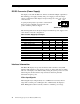
EL552.256-Q2 DC/DC Converter (Power Supply) The display comes with the PS512-6, which is an efficient multiple-output DC-toDC switching power supply assembly. The power supply provides the unique voltage requirements for EL displays. Its input voltages are +12V only or both +12V and +5V. EXT. INT. A square-pin jumper (J4) is provided to select between these two input configurations and is in the +5V position when the product is shipped.
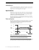
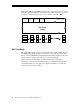
The end of the top line of a frame is marked by VS, vertical sync signal as shown in Figure 3. The end of each row of data is marked by HS. Horizontal Timing HS 3 6 VCLK 4 5 7 8 VID 0-3 Pixels: w x y z Pixels: a b c d Vertical Timing VS 10 9 11 1 2 HS First Line VID Data Figure 3. Video Input Timing Diagram Timing is compatible with LCD graphics controllers such as the SMOS and C&T display controllers. Table 4.
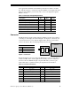
EL552.256-Q2 Input signals VID0 through VID3 contain the video data for the screen. As shown in Figure 4, pixel information is supplied from left to right and from top to bottom, four pixels at a time. Video data for one row is latched on the fall of HS. 1,2,3,4 5,6,7,8 9,10,11,12 13,14,15,16 549, 550, 551, 552 Row 1 EL Panel (Front) VID3 1 5 9 13 549 VID2 2 6 10 14 550 VID1 3 7 11 15 551 VID0 4 8 12 16 552 Figure 4. Pixel Location vs.
Optical Table 5. Optical Specifications Luminance Lon (areal), min Lon (areal), typ Loff (pixel), max 34.5 cd/m² 50 cd/m² 0.2 cd/m² screen center, 120 Hz frame rate screen center, 120 Hz frame rate 5 points: center plus four corners measured 1.0 ± 0.
EL552.256-Q2 Environmental Table 6. Environmental Specifications Temperature* Operating Non-operating 0 to +65 °C -40 °C to +75 °C Humidity Non-condensing to 93% RH max @40 ºC, per IEC 68-2-3 Altitude Tested per IEC 68-2-13 16,000 ft. (4.8 km) 58,000 ft. (17.7 km) Vibration (random) (Operating/nonoperating) 0.02 g2/Hz at 20-500 Hz for 30 minutes on each axis, per IEC 68-2-36, test Fdb.
Mechanical Specifications Table 7. Mechanical Specifications Display External Dimensions Height w/o mounting tabs Width Depth* 109.73 (4.32) 98.68 (3.885) 176.78 (6.96) 16.26 (0.64) DC/DC Converter Dimensions Height Width Length 19.05 (0.750) 50.8 (2.0) 133.35 (5.250) Display Weight 262 grams (0.6 lbs.), nominal DC/DC Converter Weight 9.33 grams (0.187 lbs.) Fill Factor 59.2% nominal Active Area Width Height Diagonal 67.564 (2.660) 145.745 (5.738) 6.33" Width Height 0.203 (0.008) 0.203 (0.
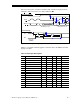
EL552.256-Q2 Dimensions of the display are in millimeters; inches are in brackets. Dimensions of the DC/DC Converter are in inches; millimeters in brackets. Some hidden lines are omitted for clarity. Figure 5. Display Dimensions Note: The dimensions in this drawing are approximate. Please contact Planar Applications Engineering to request the actual drawing prior to beginning your design. 12 EL552.
Description of Warranty This description is not the full warranty, and should not be construed as a substitute for the full warranty. A copy of the full warranty is available upon request. Planar warrants that the goods it sells will be free of defects in materials and workmanship, and that these goods will substantially conform to the specifications furnished by Planar, and to any drawings or specifications furnished to the Seller by the Buyer if approved by the Seller.
North & South America OEM Sales Europe & Asia-Pacific OEM Sales Federal & End-User System Sales Planar Systems, Inc. 1400 NW Compton Drive Beaverton, OR 97006-1992 Tel. (503) 690-1100 Fax (503) 690-1493 sales@planar.com app_eng@planar.com Planar Systems, Inc. P.O. Box 46 Olarinluoma 9 FIN-02201 Espoo, Finland Tel. +358-9-42 0010 Fax +358-9-422 143 intlsales@planar.com tech_support@planar.com Planar Advance, Inc. P.O. Box 4001 13950 Karl Braun Drive Beaverton, OR 97076-4001 Tel.