LC1200R High-Bright Monitor USER’S MANUAL www.planar.
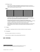
TABLE OF CONTENTS 1 INTRODUCTION 4 2 BASIC CONSTRUCTION 4 2.1 LCD Display 4 2.2 Weight 5 2.3 Mechanical 5 2.4 Cooling Fans 7 2.5 Connectors 7 2.6 Interface Cables 7 2.7 Power Supply 8 2.8 LCD Controller Board 8 2.9 Inverter Board 8 2.10 Photodiode Board 8 2.11 Button Board 9 3 ENVIRONMENTAL 9 3.1 Temperature and Humidity 3.2 Direct Sunlight Operation 10 3.3 Altitude 10 3.4 Mechanical Vibration and Shock 10 4 9 VIDEO SIGNAL REQUIREMENTS 11 4.
7.3 Display Uniformity 23 7.4 Display Chromaticity 23 8 DISPLAY COSMETICS 24 8.1 Black Display Picture Mode 24 8.2 White Display Picture Mode 24 9 REGULATORY AGENCY REQUIREMENTS 24 9.1 Safety Certification 24 9.2 CE Marketing 24 9.3 RFI Emission Certification 25 9.4 System Transient Disturbance Requirements 25 9.5 Labeling 25 9.6 ROHS Compliance 26 10 RELIABILITY 26 10.1 Design Workload 26 10.
1 Introduction This document defines the electromechanical parameters and operating characteristics for The Planar Systems, Inc. LC1200R, Very High Bright, 12.1” Active Matrix Liquid Crystal Display (AMLCD) based product. It is intended for operation as a component in a high ambient light, outdoor system. The LC1200R has a scaleable video format capable of displaying a minimum of VGA (640 x 480) through XGA (1024 x 768) input resolution.
2.1.2 Display format The LC1200R is compatible with IBM VGA1 and VESA2 video standards. Its operating frequency range is 31.5 kHz to 56.5 kHz horizontal; 60 Hz to 72 Hz (non-interlaced) vertical.
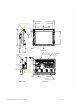
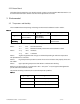
301 246 Active area 4X M3 m nt holes 123 A 92.50 B 185 Active area 235 152.15 Active Area Center 63 83 Top of rem ovable standoff 4X M3 m nt holes Front View Door to User control Connectors Rem ovable Button Board Power 12 V VGA Conn 4X Fan inlet 57.5 185.
2.4 Cooling Fans Four (4) thermostatically controlled cooling fans are provided to cool the rear of the display. The thermostat is set to turn the fans on when the video board temperature reaches 30° C. If the display is used in direct sunlight, airflow must be directed across the front of the display or the display LCD fluid may reach its clearing point, then the LC1200R will become temporarily unreadable. 2.5 Connectors There are four connectors supplied as an integral part of the LC1200R. 2.5.
2.7 Power Supply The LC1200R does not ship with a power supply. It is recommended that the Planar Systems, Inc. power adapter, part number 997-3066-00 (US) or 997-3067-00 (EU) be purchased with each unit. Refer to Section 5 for power requirements. 2.8 LCD Controller Board The LCD controller board incorporates components necessary to drive the LCD panel. Accepting VGA and VESA video standards (Section 1.2), these video signals are digitized and processed for the LCD panel.
2.11 Button Board The button board controls the user controls noted in Section 6.1 LCD Controller Board Controls It can be removed or mounted in another area after initial adjustments are made. 3 Environmental 3.1 Temperature and Humidity The LC1200R withstands operating and storage environmental conditions listed in Table 2.
3.2 Direct Sunlight Operation This monitor will absorb approximately 45 W of solar power on the front surface of the display in a typical setup when facing the sun directly. It is the integrator’s responsibility to design a system that cools the front surface adequately. Otherwise, the display’s LC material will overheat and temporarily phase change. The display will temporarily become black and unreadable. 3.3 Altitude Maximum operating altitude is 3,000 meters [9,850 feet].
4 Video Signal Requirements 4.1 Video Input Lines The video signal connector that connects to the customer’s equipment is a female 15-pin connector in a high density 9-pin D-Shell housing. Pin number assignments are defined in Table 4, and physical layout as seen by the interface cable from user logic is shown in Error! Reference source not found. The "NC" positions of this connector are not used for any purpose.
defined as a level between 0-mv and 10-mv. The white state (full white) is dependent on the VGA controller driving the LC1200R. Maximum levels may range from 550-mv to 714-mv. Nominal 680-mv input voltage shall be defined as the default for supplier setup requirements. Displayed image intensity and colors will change linearly with the video analog input. This is necessary to provide a uniform user color change on the screen in response to a uniformly stepped analog input.
Figure 4 TTL Allowable Signal Levels LC1200R User’s Guide 021-0183-00 Rev A 13 of 29
4.2.3 Mode Detection The polarity of incoming horizontal/vertical frequencies and synchronization pulses define the video resolution being presented. Video modes are listed in Table 5 Video Mode Definitions. Table 5 Video Mode Definitions Video Mode IBM VGA IBM VGA IBM VGA w/Border IBM VGA IBM VGA w/Border VESA VESA Displayed Image Resolution 640 x 400 640 x 480 656 x 496 Scanning Frequency) Sync Polarity Horizon tal (KHz) 31.468 31.468 31.
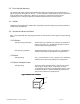
4.4 Timing and Frequency 4.4.1 Video, Horizontal and Vertical Sync Figure 6 illustrate video timing relationships the LC1200R operates within when the specified video mode (Table 5 Video Mode Definitions) is applied. Front Porch defines the time from end of active video data to the start of Horiz/Vert Sync Pulse. Back Porch defines the time from end of Horiz/Vert Sync Pulse to the start of active video data. Blanking is the total time comprising Front Porch, Back Porch and Sync Pulse time(s).
Pulse Vertical Front Porch 0.381 ms 12 lines 0.318 ms 10 lines 0.770 ms 37 lines 0.053 ms 3 lines Vertical Back Porch 1.112 ms 35 lines 1.049 ms 33 lines 0.478 ms 23 lines 0.514 ms 29 lines Vertical Active 12.711 ms 400 15.254 ms 480 12.480 ms 600 13.599 ms 768 Display lines lines lines lines Vertical Sync Polarity Note: VGA border is not included in the active display time described above. Note: For video mode 720 x 400 missing video rows and columns are allowed. This is a text mode only.
The LC1200R is not damaged by input voltages ranging from 0-vdc to 12.4-vdc. 5.3 Power On-Off Sequences The LC1200R will automatically return to normal operation upon resumption of power after a power loss. 6 User Controls 6.1 LCD Controller Board Controls The display comes from the factory adjusted for the supported modes. When using these modes, adjustment should not be necessary.
The Gain adjustment is to allow the full scale of the input video to be utilized. The direction of this adjustment will reverse when a limit is reached. For example, it will adjust from maximum to minimum, then reverse and go from minimum to maximum. The best way to make this adjustment is with a continuous gray scale pattern on the display. A proper adjustment will give continuous shading from black to white.
6.2.2 Max Bright Jumper The photodiode board can be removed from the system. When the photodiode board is unplugged the LC1200R will default to the minimum brightness mode. If the user would like to display to run at maximum brightness, the MAX BRIGHT, JP1, jumper must be inserted on the inverter board.
6.3 Dimming 6.3.1 Photodiode Board and Automatic Dimming Connector The photodiode board must be mounted in the user’s system so that the photodiode is exposed to the ambient light. In bright conditions, the LC1200R will adjust to maximum brightness. In dark conditions, the LC1200R will adjust to approximately 25% of the maximum luminance. Connector Pin Assignments are in Table 8 Table 8 Pin 1 2 3 Description Output from photodiode anode 5V input from the LC12F for photodiode cathode No connection 6.3.
The typical monitor brightness vs. ambient is as follows: Figure 9. Monitor Brightness vs. Ambient 1600 1400 Brightness, nits 1200 1000 800 600 400 200 0 0 100 200 300 400 500 600 700 800 900 1000 Ambient, lux 6.3.4 Manual Brightness Mode For manual brightness mode, apply a 0-5V input voltage to the DIM pin on the dimming control connector. The DIM input will override any input from the photodiode board. Note that the photodiode board may be left disconnected if not used.
Figure 10 1600 1400 Brightness, nits 1200 1000 800 600 400 200 0 1 1.5 2 2.5 3 3.5 4 DIM input, volts 6.3.5 Maximum Brightness Mode If constant maximum brightness is desired, a jumper may be installed at location JP1 on the inverter board. The jumper will force the LC1200R to maximum brightness unless the /DISABLE input is active. Use a 0.1 inch jumper such as Molex, part number 15-29-1024. 7 Monitor Performance 7.
C= ON white - light luminance OFF black - background luminance Display View Angle 7.3 110 Hor. -35 . + 55 vert. CR> 10 Planar LC12 Viewing Angle Planar LC12 Viewing Angle 400 300 350 250 Contrast Ratio Contrast Ratio 300 250 200 150 200 150 100 100 50 50 0 0 -80 -60 -40 -20 0 20 40 60 80 Vertical Viewing Angle (°) 7.
White color is concentrated around 5600ºK color temperature. 8 Display Cosmetics The external visual inspection shall be conducted with the unaided eye at a minimum of 35 cm [14in] from the display surface. There are acceptable defects when the display is in the black mode and in the white mode. 8.1 Black Display Picture Mode Power up the Monitor. Display an all black screen via the video input. • • 8.
Council Directive 89/336/EEC, 92/31/EEC and 93/68/EEC (Latest Amendment) on the approximation of the laws of the Member States relating to electromagnetic compatibility is based on compliance with the following harmonized standards: • • 9.3 Electromagnetic Emissions EN 55022 Class A: 1994 Electromagnetic Immunity EN 50082 part 1:1992 RFI Emission Certification The LC1200R is certified to the following emissions standards when installed in customer product configuration: • • • • 9.
Figure 11 Sample of Product labeling 9.6 ROHS Compliance This product will be compliant by June 30, 2006 10 Reliability 10.1 Design Workload The LC1200R is capable of operating 24 hours a day, 365 days a year under the specified environmental conditions per Section 3 10.2 MTBF The MTBF (mean time between failures) value excludes the fluorescent backlight assembly The LC1200R MTBF is > TBD hours.
claim notice and only after receiving Seller’s Return Goods Authorization. Seller shall, at its sole option, repair or replace the Goods. If Goods were repaired, altered or modified by persons other than Seller, this warranty is void. Conditions resulting from normal wear and tear and Buyer's failure to properly store, install, operate, handle or maintain the Goods are not within this warranty. Repair or replacement of Goods is Seller’s sole obligation and Buyer's exclusive remedy for all claims of defects.
Hours: M-F, 7:00am - 4pm CET 13 Glossary of Terms Aspect Ratio: The ratio of width to height of a display surface. The standard television aspect ratio is 4:3. Back Porch: The portion of a composite display signal which lies between the trailing edges of a horizontal sync pulse and the corresponding blanking pulse. Black Level: The display-signal level corresponding to a specified limit for black peaks.
Luminance: Luminous intensity reflected or emitted by a surface in a given direction per unit of apparent area. Measured in nits. Lumen: The unit of luminous flux or rate of luminous energy flow. It is equal to the flux radiating through a unit solid angle (steradian) from a uniform point source of one candela. Luminous Flux: The time rate of luminous energy flow, measured by its capacity to evoke a visual sensation. It is expressed in lumens.