PE2010
The information contained in this document is subject to change without notice. This document contains proprietary information that is protected by copyright. All rights are reserved. No part of this document may be reproduced, translated to another language or stored in a retrieval system, or transmitted by any means, electronic, mechanical, photocopying, recording, or otherwise, without prior written permission. Windows is a registered trademark of Microsoft Inc.
TABLE OF CONTENTS For Your Safety For Your Safety ------------------------------------------------------- 4 General Notes ------------------------------------------------------------------------------------------------- Special notes on LCD monitors Other notes 6 6 Before You Operate The Monitor Features ---------------------------------------------------------------------------------------------- Checking the contents of the package 8 8 Installation Instructions ---------------------------------
FOR YOUR SAFETY Before operating the monitor, please read this manual thoroughly. This manual should be retained for future reference. FCC Class B Radio Frequency Interference Statement WARNING: (FOR FCC CERTIFIED MODELS) NOTE: This equipment has been tested and found to comply with the limits for a Class B digital device, pursuant to Part 15 of the FCC Rules. These limits are designed to provide reasonable protection against harmful interference in a residential installation.
PRECAUTIONS z Do not use the monitor near water, e.g. near a bathtub, washbowl, kitchen sink, laundry tub, swimming pool or in a wet basement. z Do not place the monitor on an unstable cart, stand, or table. If the monitor falls, it can injure a person and cause serious damage to the appliance. Use only a cart or stand recommended by the manufacturer or sold with the monitor. If you mount the monitor on a wall or shelf, use a mounting kit approved by the manufacturer and follow the kit instructions.
GENERAL NOTES SPECIAL NOTES ON LCD MONITORS The following symptoms are normal with LCD monitor and do not indicate a problem. • • • • • Due to the nature of the fluorescent light, the screen may flicker during initial use. Turn off the Power Switch and then turn it on again to make sure the flicker disappears. You may find slightly uneven brightness on the screen depending on the desktop pattern you use.
GENERAL NOTES (cont.) • • Plug & Play DDC1/2B Feature - This monitor is equipped with VESA DDC1/2B capabilities according to the VESA DDC STANDARD. It allows the monitor to inform the host system of its identity and, depending on the level of DDC used, communicate additional information about its display capabilities. The communication channel is defined in two levels, DDC1 and DDC2B. The DDC1 is a unidirectional data channel from the display to the host that continuously transmits EDID information.
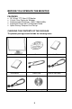
BEFORE YOU OPERATE THE MONITOR FEATURES • 20” (51cm) TFT Color LCD Monitor • Crisp & Clear Display for Windows • Recommended Resolution: 1400 X 1050 @ 60Hz • Ergonomic Design with Tilt Adjustable Stand • Space Saving, Compact Case Design CHECKING THE CONTENTS OF THE PACKAGE The product package should include the following items: Monitor User Manual 24-Pin DVI Cable Base Landing Strip Power Cord 15-pin D-Sub Cable Planar Product Family CD 8
INSTALLATION INSTRUCTIONS Power Source: 1. Make sure that the power cord is the correct type required in your area. 2. This LCD monitor has an internal Universal Power Supply that allows operation in either 100/120V AC or 220/240V AC voltage area (No user adjustment is required.) 3. Connect the AC-power cord into your LCD monitor’s AC-power-input.
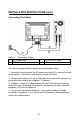
INSTALLATION INSTRUCTIONS (cont.) Connecting The Cables Figure 2 Connecting Cables 1. AC Power Cord 3. DVI Cable 2. 15-pin D-SUB Cable Turn off your computer before performing the procedure below. 1. Connect the female end of the AC power cord to the AC-in port on the back of the monitor. Connect the other end to a nearby AC-outlet. 2. Connect one end of the 15-pin D-Sub cable to the back of the monitor and connect the other end to the computer’s D-Sub port. 3.
INSTALLATION INSTRUCTIONS (cont.) ADJUSTING THE VIEWING ANGLE For optimal viewing it is recommended to look at the full face of the monitor, then adjust the monitor's angle to your own preference. Hold the stand so you do not topple the monitor when you change the monitor's angle. You are able to adjust the monitor's angle from -5° to 20°. Figure 3 NOTES • Do not touch the LCD screen when making the adjustments above. It may cause damage or break the LCD screen.
OPERATING INSTRUCTIONS (cont.) EXTERNAL CONTROLS Figure 4 - External Controls 1. 2. 3. 4. SOURCE Auto Config / Exit ∧ /ECO changing ∨ / Bri / con 5. Menu / Enter 6. Power Indicator 7. Power Button • Power Button: Press this button to turn the monitor ON or OFF. • MENU / ENTER: Active OSD menu or function adjust confirm. • ∧ / ECO ECO switching • ∨ / Bri /Con Bri /Con adjusting • Source Select the VGA or DVI function.
OPERATING INSTRUCTIONS (cont.) • Auto Adjust button / Exit: 1. 2. When OSD menu is in active status, this button will act as EXIT-KEY (EXIT OSD menu) or go back to the previous menu. When OSD menu is in off status, press this button for 2 seconds to activate the Auto Adjustment function. The Auto Adjustment function is used to set the HPos, VPos, Clock and Focus. • Power Indicator: Green Amber — — Power On mode. Standby mode.
OPERATING INSTRUCTIONS (cont.) How To Adjust A Setting 1. Press the MENU-button to activate the OSD window (Figure 5). 2. Press ∧or ∨ to navigate through the functions. Once the desired function is highlighted, press the MENU-button to activate it. If the function selected has a sub-menu, press ∧ or ∨ again to navigate through the sub-menu functions. Once the desired function is highlighted, press MENU-button to activate it. 3. Press ∧ or ∨ to change the settings of the selected function. 4.
OPERATING INSTRUCTIONS (cont.) ADJUSTING THE PICTURE The descriptions for function control LEDS Main Menu Item Main Menu Icon Sub Menu Item Sub Menu Icon Description Reset Value Contrast Contrast from Digital- Recall Warm register. Contrast Value Brightness Backlight Adjustment Focus Adjust Picture Phase to reduce HorizontalLine noise Clock Adjust picture Clock to reduce Vertical-Line noise. Adjust the horizontal position of the picture.
OPERATING INSTRUCTIONS (cont.) Analog N/A Select input signal from analog source (D-Sub) Digital N/A Select input signal from digital source (DVI) Input Select OSD Setup H. Position V. Position OSD Timeout Adjust the horizontal position of the OSD. 50 Adjust the vertical position of the OSD. 50 Adjust the OSD timeout. 10 English Language Information N/A Set OSD display language to English. Deutsch N/A Set OSD display language Select to German.
TECHNICAL SUPPORT (FAQ) (cont.) Problem & Question Power LED is not on No Plug & Play Picture is fuzzy Picture bounces or a wave pattern is present in the picture The power LED is ON (Amber) but there’s no video or no picture. Missing one of the primary colors (RED, GREEN, or BLUE) Screen image is not centered or sized properly.
TECHNICAL SUPPORT (FAQ) (cont.) CLOCK (pixel frequency) controls the number of pixels scanned by one horizontal sweep. If the frequency is not correct, the screen shows vertical stripes and the picture has not correct width. FOCUS adjusts the phase of the pixel clock signal. With a wrong phase adjustment the picture has horizontal disturbances in light picture. For FOCUS and CLOCK adjustment use “dot-pattern” or win 95/98 shut-down mode pattern. ERROR MESSAGE & POSSIBLE SOLUTION CABLE NOT CONNECTED : 1. 2.
APPENDIX SPECIFICATIONS LCD Panel Driving system Size Pixel pitch Viewable angle Video Input H-Frequency V-Frequency Display Colors Max. Resolution Plug & Play EPA ENERGY STAR® ON Mode OFF Mode Input Connector Input Video Signal TFT Color LCD 51cm(20") 0.2916mm( H )x 0.2916mm( V ) 160° (H) 160° (V) R,G,B Analog Interface Digital interface 30KHz – 82Hz 60-75Hz 16.2M Colors 1400 x 1050 @ 60Hz VESA DDC1/2BTM ≤41 W ≤1W D-Sub 15pin DVI 24pin Analog:0.
APPENDIX (cont.) • • • • • • • • • • • • • • • • • • • • • • Switch External Controls: Functions Power Consumption ( Maximum ) Regulatory Compliance 20 Source Auto Config / Exit ∧ / ECO ∨ / Bri/Con Menu / Enter Power Button Contrast Brightness Focus Clock H.Position V.
APPENDIX (cont.) Preset Display Modes STANDARD IBM DOS RESOLUTION HORIZONTAL FREQUENCY(KHZ) VERTICAL FREQUENCY(HZ) 720 × 400 31.47 70.0 640 × 480 31.47 60.0 640 × 480 37.50 75.0 800 × 600 37.879 60.0 800 × 600 46.875 75.0 1024 × 768 48.363 60.0 1024 × 768 56.476 70.0 1024 x 768 60.02 75.0 1024 x 768 48.780 60.0 1024 x 768 60.241 75.0 VGA SVGA VESA XGA SXGA SGXA 1280 × 1024 64.00 60.0 1280 × 1024 80.00 75.0 1400 x 1050 75.00 60.
APPENDIX (cont.) Connector Pin Assignment 1 5 6 10 11 15 15 - Pin Color Display Signal Cable PIN NO. 1. 2. 3. 4. 5. 6. 7. 8. DESCRIPTION Video-Red Video-Green Video-Blue NC Ground GND-R GND-G GND-B PI N NO. 9. 10. 11. 12. 13. 14. 15.
APPENDIX (cont.) 24 - Pin Color Display Signal Cable PIN NO. 1. 2. 3. 4. 5. 6. 7. 8. 9. 10. 11. 12. DESCRIPTION TMDS Data 2TMDS Data 2+ TMDS Data 2/4 Shield TMDS Data 4TMDS Data 4+ DDC Clock DDC Data NC TMDS Data 1TMDS Data 1+ TMDS Data 1/3 Shield TMDS Data 3- PI N NO. 13. 14. 15. 16. 17. 18. 19. 20. 21. 22. 23. 24.
2006 Q41G2002935 1A