PL1520M
1195 NW Compton Drive Beaverton, OR 97006-1992 www.planar.com Customer Service Planar provides the following technical support services: Internet Support For support available 24/7 visit Planar's Online Technical Support at www.planar.com/support. Our Online Technical Support is where you'll find solutions to many common problems, download documentation, view answers to frequently asked questions (FAQs) and get troubleshooting advice, or email Planar your support question.
The information contained in this document is subject to change without notice. This document contains proprietary information that is protected by copyright. All rights are reserved. No part of this document may be reproduced, translated to another language or stored in a retrieval system, or transmitted by any means, electronic, mechanical, photocopying, recording, or otherwise, without prior written permission. Windows is a registered trademark of Microsoft Inc.
TABLE OF CONTENTS For Your Safety For Your Safety --------------------------------------------------------------3 General Notes Special notes on LCD monitors -----------------------------------------5 Before You Operate The Monitor Features -----------------------------------------------------------------------6 Checking the contents of the package --------------------------------6 Installation Instructions Installing the base------------------------------------------------------------7 Power source -------
For Your Safety Before operating the monitor, please read this manual thoroughly. This manual should be retained for future reference. FCC Class B Radio Frequency Interference Statement WARNING: (FOR FCC CERTIFIED MODELS) NOTE: This equipment has been tested and found to comply with the limits for a Class B digital device, pursuant to Part 15 of the FCC Rules. These limits are designed to provide reasonable protection against harmful interference in a residential installation.
PRECAUTIONS z Do not use the monitor near water, e.g. near a bathtub, washbowl, kitchen sink, laundry tub, swimming pool or in a wet basement. z Do not place the monitor on an unstable cart, stand, or table. If the monitor falls, it can injure a person and cause serious damage to the appliance. Use only a cart or stand recommended by the manufacturer or sold with the monitor. If you mount the monitor on a wall or shelf, use a mounting kit approved by the manufacturer and follow the kit instructions.
GENERAL NOTES SPECIAL NOTES ON LCD MONITORS The following symptoms are normal with LCD monitor and do not indicate a problem. NOTES • Due to the nature of the fluorescent light, the screen may flicker during • • • • initial use. Turn off the Power Switch and then turn it on again to make sure the flicker disappears. You may find slightly uneven brightness on the screen depending on the desktop pattern you use. The LCD screen has effective pixels of 99.99% or more. It may include blemishes of 0.
BEFORE YOU OPERATE THE MONITOR FEATURES • • • • • 38.1cm(15”) TFT Color LCD Monitor Crisp, Clear Display for Windows Recommened Resolutions: 1024 x 768 @60Hz Ergonomic Design Space Saving, Compact Case Design CHECKING THE CONTENTS OF THE PACKAGE The product package should include the following items: 1. 2. 3. 4. 5. 6. 7. 8. Monitor Base Landing Strip User Manual Power Cord 15-Pin D-Sub Cable Audio Cable Composite Video Cable Register Your Planar Products Today Thank you for choosing Planar.
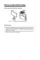
INSTALLATION INSTRUCTIONS INSTALLING AND REMOVING THE BASE: Install Figure 1 Remove Installing and Removing the Base Power Source: 1. Make sure that the power cord is the correct type required in your area. 2. This LCD monitor has an Internal universal power supply that allows operation in either 100/120V AC or 220/240V AC voltage area (No user adjustment is required.) 3. Connect the AC-power cord one end to your LCD monitor’s AC-input socket , the other end to wall-outlet .
INSTALLATION INSTRUCTIONS CABLE CONNECTIONS ·Connecting the Signal Cable: Plug one end of the VGA Cable to the LCD monitor’s “ VGA” input socket , the other end to the computer's VGA port and tighten the two screws on the cable connector. ·Connecting the Power Cord: Plug one end of the AC-power cord to the LCD monitor’s AC input socket , the other end to a wall outlet.
INSTALLATION INSTRUCTIONS ADJUSTING THE VIEWING ANGLE • For optimal viewing it is recommended to look at the full face of the monitor, then adjust the monitor’s angle to your own preference. • Hold the stand so you do not topple the monitor when you change the monitor’s angle. • You are able to adjust the monitor’s angle from -5° to 20°. Figure 3 NOTES • Do not touch the LCD screen when you change the angle. It may cause damage or break the LCD screen.
OPERATING INSTRUCTIONS GENERAL INSTRUCTIONS Press the power button to turn the monitor on or off. The other control buttons are located at front panel of the monitor (See Figure 4). By changing these settings, the picture can be adjusted to your personal preferences. • The power cord should be connected. • Connect the Signal cable from the monitor to the VGA card. • Connect video/S-video cable from the monitor to a video source . • Press the power button to turn on the monitor.
OPERATING INSTRUCTIONS(cont.) FRONT PANEL CONTROL KNOBS • Power Button /Power Indicator: Press this button to switch ON/OFF of monitor’s power. Green — Power On mode. Amber — Power saving mode • MENU / ENTER OR ADJUST : 1. 2. 3. When OSD menu is not activated, press this button to activate the OSD menu. When OSD menu is in activated, this button will act as an Enter key. For certain functions when OSD menu is activated, this button will also act as an Adjust button. • “VOL+” and ">" button: 1. 2.
OPERATING INSTRUCTIONS(cont.) OSD Lock Function: Option 1: OSD lock - all 4 buttons are locked except the "POWER" button. Press and hold the "MENU" and ">" buttons for 3 seconds to lock the buttons. Repeat this step to unlock. Option 2: OSD & Power button lock - all 5 buttons including the "POWER" button are locked. Press and hold the "MENU" and "<" buttons for 3 seconds to lock all 5 buttons. Repeat this step to unlock.
OPERATING INSTRUCTIONS (cont.) HOW TO ADJUST A SETTING Press the “MENU” key to activate the OSD window. 1. Press < or > to navigate through the functions. Once the desired function is highlighted, press the “MENU” key again to activate it. If the function selected has a sub-menu, press < or > again to navigate through the submenu functions. Once the desired function is highlighted, press “MENU” key to activate it. 2. Press < or > to change the settings of the selected function. 3.
OPERATING INSTRUCTIONS (cont.) MENU SELECTION Main Menu Main Menu Item Icon Description Note Video Picture set up for composite video & s-video mode. Inactive when VGA source is selected. Sound Sound set up for all modes.
OPERATING INSTRUCTIONS (cont.) SOURCE SET UP Source select between VGA, Composite Video and S-Video. Source Setting 1. Press “ MENU” key to open OSD menu 2. Press>or or or or
OPERATING INSTRUCTIONS (cont.) Sound Setup Sets up sound for all modes. VGA, Composite Video & S-Video Sound Setting 1. Press “ MENU” key to open OSD menu 2. Press>or or or or
OPERATING INSTRUCTIONS (cont.) VGA Picture Setting When the input source is in VGA (PC) mode, you can select Brightness, Contrast, H/V Position, Clock, Phase, AUTO, Color, and Reset as shown in the figure below: VGA Picture Setting 1. Press “ MENU” key to open OSD menu 2. Press>or or or
OPERATING INSTRUCTIONS (cont.) ·V-position 1. Press>or or or or or
OPERATING INSTRUCTIONS (cont.) ·COLOR 1. Press>or or or
OPERATING INSTRUCTIONS (cont.) Video Picture Setting When the input source is in Video or S-Video mode, there are four pictures modes to select: Custom, Standard, Soft & Vivid. Only Custom mode allows you to adjust Brightness, Contrast, Hue, Saturation and Sharpness. VIDEO Picture Setting (Composite video/ S-Video mode) 1. Press “ MENU” key to open OSD menu 2. Press>or
OPERATING INSTRUCTIONS (cont.) ·SATURATION 1. Press>or or or or or
OPERATING INSTRUCTIONS (cont.) ·BLACK LEVEL 1. Press>or or
OPERATING INSTRUCTIONS (cont.) OSD (On Screen Display) SET UP When the input source is in VGA, Composite video or S-Video mode, you can adjust OSD as shown in the figure below: OSD Setting 1. Press “ MENU” key to open OSD menu 2. Press>or or
OPERATING INSTRUCTIONS (cont.) ·TRANSPARENCY 1. Press>or or or or
OPERATING INSTRUCTIONS (cont.) PLUG AND PLAY Plug & Play DDC2B Feature This monitor is equipped with VESA DDC2B capabilities according to the VESA DDC STANDARD. It allows the monitor to inform the host system of its identity and, depending on the level of DDC used, communicate additional information about its display capabilities. The DDC2B is a bidirectional data channel based on the I²C protocol. The host can request EDID information over the DDC2B channel.
TECHNICAL SUPPORT (FAQ) Problem & Question Power LED is not on No Plug & Play Picture is fuzzy Picture bounces or a wave pattern is present in the picture The power LED is ON (Amber) but there’s no video or no picture. Missing one of the primary colors (RED, GREEN, or BLUE) Screen image is not centered or sized properly.
TECHNICAL SUPPORT (FAQ) (cont.) CLOCK (pixel frequency) controls the number of pixels scanned by one horizontal sweep. If the frequency is not correct, the screen shows vertical stripes and the picture has not correct width. FOCUS adjusts the phase of the pixel clock signal. With a wrong phase adjustment the picture has horizontal disturbances in light picture. For FOCUS and CLOCK adjustment use “dot-pattern” or win 95/98 shut-down mode pattern. ERROR MESSAGE & POSSIBLE SOLUTION NO SIGNAL: 1. 2.
APPENDIX SPECIFICATIONS Items Specification Screen Size Aspect Ratio Resolution Size Pixel Pitch Display colors LCD Panel Contrast Ratio Brightness Viewing Angle Response Time 15” screen 4:3 1024x768(XGA) 38.1cm(15.0") 0.297mm x 0.297mm 16.
APPENDIX PC Input Signal Input Analog: D-Sub 15 pin (detachable cable) PnP compatibility DDC 2B Input frequency Analog:FH:30KHz to 60KHz FV:55Hz to75Hz Recommended Analog: 1024x 768 (60Hz) Input Audio mini-jack 3.5mm x 1 (Shared) Audio Output Audio Output: L / R Speaker (built-in): Max 1W Per channel Headphone Mini-jack for stereo (3.5ø) OSD language English. Simplified Chinese .French. Spanish.
APPENDIX (cont.
APPENDIX (cont.) Preset Display Modes STANDARD RESOLUTION HORIZONTAL VERTICAL FREQUENCY (kHz) FREQUENCY (Hz) VESA MODES 640x480 VGA SVGA XGA 31.47 60.0 640x480 37.50 75.0 640x480 37.861 72.8 800X600 35.156 56.3 800X600 37.879 60.0 800X600 48.077 72.2 800X600 46.875 75.0 1024X768 48.363 60.0 1024X768 56.476 70.0 1024×768 60.02 75.0 IBM MODES DOS 640x400 31.469 70.087 DOS 720X400 31.469 70.087 XGA 1024x768 57.515 72.1 MAC MODES VGA 640X480 35 66.
APPENDIX (cont.) CONNECTOR PIN ASSIGNMENT 1 5 6 10 11 15 15 - Pin Color Display Signal Cable PIN NO. 1. 2. 3. 4. 5. 6. 7. 8. DESCRIPTION Red Green Blue RXD Ground R-Ground G-Ground B-Ground PI N NO. 9. 10. 11. 12. 13. 14. 15.
1195 NW Compton Drive Beaverton, OR 97006-1992 www.planar.com © 2006 Planar Systems, Inc. Planar is a registered trademark of Planar Systems, Inc. Other brands and names are the property of their respective owners. Technical information in this document is subject to change without notice.