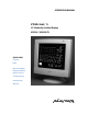
OPERATIONS MANUAL VitalScreen™ S 15" Medically Certified Display VSS15X / VSS15X-TR QUICK LINKS Contents Index About the Display Display Installation Display Controls Troubleshooting Ordering Parts Warranty
Americas Sales Planar Systems, Inc. 1195 NW Compton Drive Beaverton, OR 97006-1992 USA (503) 748-1100 phone (503) 748-1493 fax Medical Sales Planar Systems, Inc. 400 Fifth Avenue Waltham, MA 02451-8738 USA (781) 895-1155 phone (781) 895-1133 fax Europe & Asia-Pacific Sales Planar Systems, Inc. Olarinluoma 9, P. O. Box 46 FIN-02201 Espoo, Finland + 358 9 420 01 phone + 358 9 420 0200 fax Internet address for sales information: medicalsales@planar.
iii Contents Regulatory Compliance . . . . . . . . . . . . . . . . . . . . . . . . . . . . . iv About This Manual . . . . . . . . . . . . . . . . . . . . . . . . . . . . . . . . . v Product Information . . . . . . . . . . . . . . . . . . . . . . . . . . . . . . . vi 1 About the VitalScreen S . . . . . . . . . . . . . . . . . . . . . . . . . . . . 1 Selecting a Workspace . . . . . . . . . . . . . . . . . . . . . . . . . . . . . . . . . 1 Unpacking the Display . . . . . . . . . . . . . . . . . . . . . . .
iv Regulatory Compliance This display has been tested and certified to international medical safety standards IEC/EN 60601-1 and IEC/EN 60601-1-2, and is certified to meet C22.2 No. 601.1-M1990 (C US Mark). Because many medical offices are located in residential areas, the medical display, in addition to meeting medical requirements, has also been tested and found to comply with the limits for Federal Communications Commission (FCC) Class B computing devices in a typically configured system.
v Planar Systems, Inc., located in Beaverton, Oregon, USA, is the manufacturer of these displays in the meaning of the directive. As required by the MDD in Article 14, Planar Systems, Inc., not residing in the European Economic Area (EEA), has a European representative, Planar Systems, Inc.—Espoo, Finland. In the opinion of Planar Systems, Inc.
vi Product Information Safety instructions Store the display in its original shipping carton when it is not in operation for extended periods of time. Also use the original packing materials and carton when shipping the display. • Do not place the display near a window. Exposing the display to rain, water, moisture, or direct sunlight can damage it. • Do not place anything on top of the video cable. Make sure the cable is placed where it will not be stepped on.
vii Cleaning instructions Use only the products listed below for cleaning the display. The products differ for cleaning the screen and cleaning the plastic enclosure. Be sure you use only the specific products approved for either the screen or the enclosure. Always apply the product to a clean nonabrasive cloth and then wipe the screen or plastic enclosure. Cleaners applied directly to the display could leak inside a non-sealed unit and cause damage.
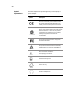
viii Symbol explanations This table explains the symbols appearing on the display or power adapter. Symbol Description Proof of conformity to applicable European Economic Community Council directives and two harmonized standards published in the official journal of the European Communities. The product has been tested and certified by CSA to C22.2 No. 601.1-M90. If this mark appears with the indicators "C" and "US," the product is certified for the Canadian and U.S.
About the VitalScreen S The architecture of the VitalScreen™ S display incorporates an AMLCD panel that produces a clear display with low radiation emission. This technology greatly reduces the radiation-related health concerns associated with CRT monitors. More significant, the VitalScreen S display is medically certified under UL 2601 and IEC 60601. These qualifications make the display safer for the patient and protect the hospital from liability.
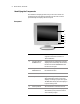
2 Model VSS15X / VSS15X-TR Identifying the Components The VitalScreen S display provides easy access to all controls and peripheral ports. The following illustrations of the front and back panels identify the display controls and ports. Front panel 1 2 3 4 5 6 7 1 LCD screen A 15-inch diagonal AMLCD. The screen supports a maximum resolution of 1024 x 768 (XGA). 2 Function UP and DOWN buttons Vertical arrows to navigate the onscreen display menu horizontally. UP selects the functions to the left.
About the VitalScreen S 3 Back panel 1 2 3 4 1 Audio Line In Jack for the audio cable. (You can also connect the CD-ROM Line Out to this jack.) 2 Power input port (locking mini DIN connector) Port for the power connector. 3 Video connector port Port for a 2-meter cable with two 15-pin D-Sub VGA connectors; used to join the display to the VGA card in your computer. 4 Touchscreen port Port for the RS-232 cable; used to operate the optional touch screen.
4 Model VSS15X / VSS15X-TR Adjusting the Viewing Angle You can adjust your VitalScreen S display to various viewing angles. This side view of the display shows the angle settings possible, ranging from -5 to 25 degrees.
Installing the Display To install the VitalScreen S display, connect the power supply first. Next, connect the VGA cable. Then choose whether to connect optional stereo speakers and touch screen. Connecting the AC Power You must use the Ault power adapter with this display unit. 1 Plug the AC power cord into the power adapter. 2 Plug the power connector into the locking mini DIN port on the back panel. 3 Plug the power cord into a grounded wall outlet.
6 Model VSS15X / VSS15X-TR Connecting the Video Cable 1 Turn off your computer and the display before connecting the two units. 2 Plug the video cable into the D-sub VGA connector port on the back panel. 3 Plug the other end of the video cable into the VGA port on the computer. 4 Make sure the cables are properly aligned, then tighten the connecting screws to ensure a secure connection. 5 Turn on the display first and then the computer.
Installing the Display Connecting the Stereo Speakers 1 Plug the audio cable to the Line Out port on the audio card in your computer. 2 Plug the other end of the audio cable to the Line In jack on the display. 3 Adjust the volume of the stereo speakers by using the volume control function on the onscreen display menu. Note In some instances, the volume control function may be disabled. If so, the volume is set to the maximum.
8 Model VSS15X / VSS15X-TR Connecting the Optional Touch Screen 1 Plug the RS232 cable into the RS232 port on the back panel. 2 Plug the other end of the cable into the RS232 serial port on your computer. 3 Load the touchscreen driver from the CD enclosed. Power Management System The VitalScreen S display complies with the VESA DPMS power management standard. This standard provides four power-saving modes, based on the display detecting the horizontal or vertical sync signals.
Display Controls This chapter explains the onscreen display (OSD) menu: the user interface for controlling various aspects of the VitalScreen S display. The VitalScreen S display features an intuitive, menu-driven, onscreen display. Using the OSD menu, you can adjust the contrast, brightness, display position, display clarity, color temperature, and stereo speaker volume, as well as set onscreen display parameters. Use the push buttons on the front of the display to access the controls.
10 Model VSS15X / VSS15X-TR Hot Key Functions Three Hot Key functions allow you to make quick adjustments to the display setting, volume, and contrast without accessing the OSD menu. Auto Adjust. Press the Function DOWN button to apply a display setting automatically. A small Auto Adjust OSD is displayed. Audio-Volume. Press the Adjust PLUS button to change the audio volume directly. A small AudioVolume OSD is displayed. Contrast.
Display Controls 11 Function Menus The following tables describe the main menus and submenus. The Seven Main Menus Auto Adjust. Allows the display to determine and select the settings that are appropriate for your system requirements. This function tunes the display to the video card in your computer. Monitor-Control. Allows you to adjust the display characteristics such as the horizontal or vertical position, display phase, display clock, and factory reset.
12 Model VSS15X / VSS15X-TR Auto Adjust Allows the display to determine and select the settings that are the most appropriate for your system requirements. With the Auto Adjust icon selected, press either Function Enter button to apply the display settings automatically. Monitor–Control Allows you to adjust the display characteristics. With the Monitor-Control icon selected, press either Function Enter button to activate the submenu. H-Position.
Display Controls 13 OSD–Control Allows you to adjust the position of the onscreen display on the screen. With the OSD-Control icon selected, press either Function Enter button to activate the submenu. OSD-H-Position. Press the Adjust PLUS or MINUS button to move the OSD menu horizontally. OSD-V-Position. Press the Adjust PLUS or MINUS button to move the OSD menu vertically. Exit. Press either Function ENTER button to exit the OSD-Control submenu.
14 Model VSS15X / VSS15X-TR MISC–Control Allows you to select the display language, adjust the volume setting, and view system information. With the MISC-Control icon selected, press either Function Enter button to activate the submenu. Language. Press the Adjust PLUS or MINUS button to select the desired OSD display language. Languages supported: English, German, French, Spanish, and Italian. Audio Volume. Press the Adjust PLUS or MINUS button to decrease or increase the volume of the stereo speakers.
Display Controls 15 Graphic–Control Allows you to adjust the display contrast, brightness, and color settings. With the Graphic-Control icon selected, press either Function Enter button to activate the submenu. Contrast. Press the Adjust PLUS or MINUS button to adjust the difference between the lightest and darkest areas of the display. The contrast level can range from 0 to 63. Brightness.
16 Model VSS15X / VSS15X-TR Graph/Text Allows you to change the DOS resolution from 640 x 400 to 720 x 400. With the Graph/Text icon selected, press the Adjust PLUS or MINUS button to change the resolution from one setting to the other. Exit Allows you to exit the OSD menu. With the Exit icon selected, press either Function ENTER button. The OSD menu automatically exits after a brief period of inactivity.
Technical Information VSS15X/VSS15X-TR Specification Panel 15” active matrix color TFT LCD; 1024 (H) x 768 (W) pixels (XGA) Control functions power Software power switch with LED indicator (Press a minimum of 2 seconds to turn OFF/ON.) Onscreen display (OSD) Main Menu Submenu Monitor Control Auto-Adjust/H-Position/V-Position/Phase/Clock/ Reset//Exit OSD Control OSD H-Position/OSD V-Position/OSD-Timer/Exit Graphic Control Contrast/Brightness/Color/RGB/Auto-Level/ Reset/Exit Misc.
Supported Timing Item Standard Vertical Scanning Frequency (Hz) Horizontal Scanning Frequency (kHz) 1 NEC PC98 640x400 25.20 70.15 31.50 2 NEC PC98 640x400 21.05 56.42 24.83 3 MAC 13-inch mode 640x480 30.24 66.67 35.00 4 MAC 16-inch mode 832x624 57.28 74.55 49.73 5 MAC 17-inch mode 1024x768 80.00 75.02 60.24 6 VGA 640x350 25.18 70.09 31.47 7 VGA 640x400 25.18 70.09 31.47 8 VGA 640x480 25.18 59.94 31.47 9 VESA 640x480 31.50 72.81 37.
Troubleshooting Problem Display indicates “Over Range” The frequency range is outside of display specifications, or the incoming resolution is higher than 1024 x 768. Frequency range The incoming frame rate is higher than 75 Hz. The screen display may not be centered and this warning message appears Incoming resolution The incoming resolution is higher than 1024 x 768. The video data turns off and this warning message appears.
20 Appendix C Problem Display indicates “No Signal” When there is no video-input signal from the source video port, the OSD shows this message. Solution Check that the video cable is connected securely to the computer and the display.
Index A I AC power, connecting, 5 Adjust button, 2, 9 adjusting display, 9 adjusting viewing angle, 4 audio line, 3 Auto Adjust menu, 11, 12 identifying components, 2 information ordering parts, 26 product, vi technical, 17 installing display, 5 B L back panel, 3 LCD screen, 2 cleaning, vii troubleshooting, 20 C cleaning instructions, vii components, identifying, 2 connecting AC power, 5 stereo speakers, 7 touch screen, 8 VGA cable, 6 controls, display, 9 customer support, 25 D desk stand, 2 DIN co
22 Index T V technical information, 17 timing, supported, 18 touch screen cleaning, vii connecting, 8 troubleshooting, 19 VESA DPMS, 8 VGA cable, connecting, 6 connector, 3 viewing angle, adjusting, 4 W U unpacking display, 1 warranty, 23 workspace, selecting, 1
Description of Warranty Planar Systems, Inc. (Planar) warrants that the goods sold hereunder will be free of defects in materials and workmanship, and such goods will substantially conform to the specifications furnished by Planar, and to any drawings or specifications furnished to Planar by the Buyer if approved by Planar. This warranty shall be effective only if Planar receives notice of such defect or nonconformance during the period of the warranty.
Limitation of warranty The foregoing warranty shall not apply to defects resulting from (a) improper or inadequate maintenance by Buyer; (b) unauthorized modification of the goods; (c) operations of the goods outside the environmental specifications of the goods; (d) neglect, misuse, or abuse of the goods; or (e) modification or integration with other goods not covered by the Planar warranty when such modification or integration increases the likelihood of damage to the goods.
Installation Planar makes no warranty with respect to any installation of Planar product(s) by Planar, any authorized dealer, or any other person. Technical assistance In North America, call 1 (866) PLANAR1 between 8 A.M. and 5 P.M. Pacific time, Monday through Friday, or send a description of your technical issues and e-mail address to medicalsupport@planar.com. In Europe, call +358 9 420 01 between 8 A.M. and 4 P.M.
Ordering Information Non-touch display Use the information in these tables to order parts for the VSS15X non-touch display.
Resistive-touch display Use the information in these tables to order parts for the VSS15X-TR resistive-touch display.
Americas Sales Medical Sales Europe & Asia-Pacific Sales Planar Systems, Inc. 1195 NW Compton Drive Beaverton, OR 97006-1992 USA (503) 748-1100 phone (503) 748-1493 fax sales@planar.com Planar Systems, Inc. 400 Fifth Avenue Waltham, MA 02451-8738 USA (781) 895-1155 phone (781) 895-1133 fax medicalsales@planar.com Planar Systems, Inc. Olarinluoma 9, P. O. Box 46 FIN-02201 Espoo, Finland + 358 9 420 01 phone + 358 9 420 0200 fax intlsales@planar.