Contents Preface.........................................................................................................................2 Installation.................................................................................................................4 Unpacking ...............................................................................................................................................................................4 Viewing Angle Adjustment...................................
Preface This manual is designed to assist users in setting up and using the LCD Monitor. Information in this document has been carefully checked for accuracy; however, no guarantee is given to the correctness of the contents. The information in this document is subject to change without notice. This document contains proprietary information protected by copyright. All rights are reserved.
Important Safety Instructions Please read the following instructions carefully. This manual should be retained for future use. 1. To clean the LCD Monitor screen: -- Power off the LCD Monitor and unplug the AC Cord. -- Spray a non-solvent cleaning solution onto a rag. -- Gently clean the screen with dampened rag. 2. Do not place the LCD Monitor near a window. Exposing the monitor to rain water, moisture or sunlight can severely damage it. 3. Do not apply pressure to the LCD screen.
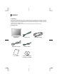
Installation Unpacking Before unpacking the LCD Monitor, prepare a suitable workspace for your Monitor and computer. You need a stable and clean surface near a wall power outlet. Make sure that the LCD Monitor has enough space around it for sufficient airflow. Though the LCD Monitor uses very little power, some ventilation is needed to ensure that the Monitor does not become too hot.
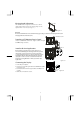
Viewing Angle Adjustment +90° The LCD Monitor is designed to allow users to have a comfortable viewing angle. The viewing angle can be adjusted from -2°to +90°.(See fig. 1-1) -2° Figure 1-1 Warning Do not force the LCD Monitor over its maximum viewing angle settings as stated above. Attempting this will result in damaging the Monitor and Monitor stand. M 4mmX11mm screw x 4 Detaching LCD Monitor from Its Stand Unscrew screws the swivel base support column and pull down the hinge to release.
Connecting the AC Power 1. Connect the power cord to the LCD Monitor.(See Fig. 1-5) 2. Connect the power cord to an AC power source. Figure 1-5 Connecting the Audio Cable 1. Connect the audio cable to the “LINE OUT “ jack on your PC's audio card or to the front panel's “AUDIO OUT” jack of your CD ROM drive. (See Fig. 1-6) 2. Connect the other end of the audio cable to the LCD Monitor's " LINE IN " jack. Figure 1-6 Connecting the USB Cable 1. 2.
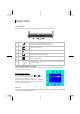
Display Controls User Controls A brief description and the location of all LCD Monitor functions controls and indicators: Figure 2-1 1 Power LED will be Green when the monitor is on, Yellow when in power saving mode, and Dark when the monitor is off. Press this button to turn on and turn off the monitor. 2 Function select (clockwise) 3 Function select (counter-clockwise) 4 Audio Volume increase / Adjust increase.
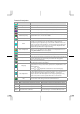
Function Description Icon Function Function Description Brightness 101 scales of brightness are available to choose from (0 to 100). Contrast 101 scales of contrast are available to choose from (0 to 100). H. Position This function let's you adjust the display's horizontal position. V. Position This function let's you adjust the display's vertical position. OSD Transparency This function let's you set the transparency of the OSD menu. The transparency is adjustable from 0 to 10.
OSD Lock Out Function When monitor is in normal display, you can enable the “OSD Lock Out” function. Option 1: OSD lock – all 4 buttons are locked except the “POWER” button. Press and hold the , and buttons for same time 3 seconds to lock the buttons. The monitor will show an “OSD Lock Out” message for 5~10 seconds and the message will disappear automatically. Repeat this step to unlock. Option 2: OSD & Power button lock – all 5 buttons including the “POWER” button are locked.
Technical Information Specifications LCD Panel Size Display Type Resolution Display Dot Display Area (mm) Display Color Lamp Voltage (typical) Lamp Current (typical) 15" (38.1 cm) Active matrix color TFT LCD 1024 x 768 1024 x (RGB) x 768 304.128 x 228.096 (H x V) 16.7M (RGB 6 bits+Hi-FRC data) 560 Vrms 8.0 mA rms. Video Input Signal Input Impedance Polarity Amplitude Multi-mode Supported Analogue RGB 0.7Vp-p 75 Ohm ± 2% Positive, Negative 0 - 0.7 ± 0.
Power Management Mode Power Consumption* AC Input LED Color 25W maximum 240 VAC GREEN DPM ON DPM OFF 2W maximum 240 VAC Yellow DC switch off 1W maximum 240 VAC Dark Meeting VESA DPM requirements measured from AC Input end of AC power cord.
Standard Timing Table If the selected timing is NOT included in table below, this LCD monitor will use the most suitable available timing.
Troubleshooting This LCD Monitor has been pre-adjusted using factory standard VGA timings. Due to the output timing differences among various VGA cards in the market, users may initially experience an unstable or unclear display whenever a new display mode or new VGA card is selected. Attention This LCD Monitor Supports Multiple VGA Modes. Refer to the Standard Timing Table for a listing of modes supported by this LCD Monitor.
Touch Screen Driver Installation The PJT155R/ PJT175R/ PJT195RW is available with USB connection. The touch software is located on the enclosed CD-ROM for these operating systems: Windows® 7, VISTA, XP, 2000, ME, 98, NT4.0, CE, XP Embedded, Linux, Apple® Mac OS Please Note: The PJT155R/ PJT175R/ PJT195RW is Microsoft® Windows® HID (Human Interface Device) compatible if you use the USB touch screen interface. No additional software driver is required for general operation of the touch screen.
PJT155R/ PJT175R/ PJT195RW Install Instructions If you are using a PC running Windows® 7, VISTA, XP, 2000, ME, 98, NT4.0, follow the instructions below: 1. Power on the PC. 2. Be sure the USB cable is connected from the PC to the LCD display. 3. Download the driver online and execute. 4. Follow the step-by-step instructions as shown on the pop-up windows. If you are using a PC running Windows® XP Embedded, follow the instructions below: Express: 1. Power on the computer. 2.
Product Registration and Technical Support Register Your Planar Products Today Thank you choosing Planar. To assure you receive all the benefits of your Planar product and services, register your Planar product today. Visit our website to register your product at http://www.planar.com/support/product_registration.
Planar Systems,Inc. Customer Service 24x7 Online Technical Support: http://www.planar.com/support 1195 NW Compton Drive Beaverton, OR 97006-1992 Tel: 1-866-PLANAR1 (866-752-6271), or +1 503-748-5799 outside the United States, Hours: 24 hours a day, 7 days a week 2012 Planar Systems, Inc. Planar is a registered trademark of Planar Systems, Inc. Other brands and names are the property of their respective owners. Technical information in this document is subject to change without notice.