PLL2010MW LED LCD Monitor
The information contained in this document is subject to change without notice. This document contains proprietary information that is protected by copyright. All rights are reserved. No part of this document may be reproduced, translated to another language or stored in a retrieval system, or transmitted by any means, electronic, mechanical, photocopying, recording, or otherwise, without prior written permission. Windows is a registered trademark of Microsoft Inc.
|| TABLE OF CONTENTS FOR YOUR SAFETY................................................................................................................3 PRECAUTIONS................................................................................................................4 SPECIAL NOTES ON LCD MONITORS......................................................................5 BEFORE YOU OPERATE THE MONITOR .........................................................................5 FEATURES .....................
|| FOR YOUR SAFETY Before operating the monitor, please read this manual thoroughly. This manual should be retained for future reference. FCC Class B Radio Frequency Interference Statement WARNING: (FOR FCC CERTIFIED MODELS) NOTE: This equipment has been tested and found to comply with the limits for a Class B digital device, pursuant to Part 15 of the FCC Rules. These limits are designed to provide reasonable protection against harmful interference in a residential installation.
PRECAUTIONS •• Do not use the monitor near water, e.g. near a bathtub, washbowl, kitchen sink, laundry tub, swimming pool or in a wet basement. •• Do not place the monitor on an unstable cart, stand, or table. If the monitor falls, it can injure a person and cause serious damage to the appliance. Use only a cart or stand recommended by the manufacturer or sold with the monitor. If you mount the monitor on a wall or shelf, use a mounting kit approved by the manufacturer and follow the kit instructions.
SPECIAL NOTES ON LCD MONITORS The following symptoms are normal with LCD monitor and do not indicate a problem. NOTES •• Due to the nature of the fluorescent light, the screen may flicker during initial use. Turn off the Power Switch and then turn it on again to make sure the flicker disappears. •• You may find slightly uneven brightness on the screen depending on the desktop pattern you use. •• The LCD screen has effective pixels of 99.99% or more. It may include blemishes of 0.
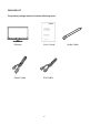
PACKAGE LIST The product package should include the following items: Monitor User's Guide Power Cable VGA Cable 6 Audio Cable
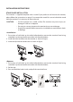
INSTALLATION INSTRUCTIONS STAND BASE INSTALLATION The monitor is supplied complete with a stand.If you prefer to wall mount the monitor, please follow the instructions on page 21 to remove the stand. Be sure to include the stand with the monitor if it is necessary to return the unit. CAUTION •• Put the monitor on a stable surface.The monitor may cause injury or damage if it falls or is dropped. •• Do not give a strong impact to the monitor.It may cause damage.
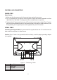
CONTROLS AND CONNECTORS POWER CORD Power Source: 1. Make sure that the power cord is the correct type required in your area. 2. This LCD monitor has an internal universal power supply that allows operation in either 100/120V AC or 220/240V AC voltage area (No user adjustment is required.) 3.
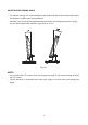
ADJUSTING THE VIEWING ANGLE •• For optimal viewing it is recommended to look at the full face of the monitor, then adjust the monitor’s angle to your own preference. •• Hold the stand so you do not topple the monitor when you change the monitor’s angle. •• You are able to adjust the monitor’s angle from -4° to 18°. 4 Figure 3 NOTES •• Do not touch the LCD screen when you change the angle. It may cause damage or break the LCD screen.
|| OPERATING INSTRUCTIONS GENERAL INSTRUCTIONS Press the power button to turn the monitor on or off. The other control buttons are located at front panel of the monitor (See Figure 4). By changing these settings, the picture can be adjusted to your personal preferences. •• The power cord should be connected. •• Connect the video cable from the monitor to the video card. •• Press the power button to turn on the monitor. The power indicator will light up. 1 2 Figure 4 1. 2. 3. 4. 5.
FRONT PANEL CONTROL •• Power Button: Press this button to switch ON/OFF monitor’s power. •• Power Indicator: Blue — Power On mode. Orange —Off mode. •• MENU / ENTER : Activates OSD menu or function adjust confirm. •• ECO/(-) Activates the ECO control when the OSD is OFF or navigate through adjustment icons when OSD is ON or adjust a function when function is activated.
HOW TO ADJUST A SETTING 1. Press the MENU-button to activate the OSD window. 2. Press + or - to navigate through the functions. Once the desired function is highlighted, press the MENU-button to activate it. If the function selected has a sub-menu, press + or - again to navigate through the sub-menu functions. Once the desired function is highlighted, press MENU-button to activate it. 3. Press + or - to change the settings of the selected function. 4.
ADJUSTING THE PICTURE Main Menu Main Menu 1st Sub Item Icon Menu Item Luminance Contrast DCR Adjusts Image brightness in relation to the background. Adjusts backlight levels. Picture Adjustment, Standard: Brightness = 90, Contrast = 50. Brightness, Contrast (Adjustable) Text: Brightness = 20, Contrast = 50. Brightness, Contrast ,Grayed. (Nonadjustable) Internet: Brightness = 40, Contrast = 50. Brightne ss, Contrast ,Grayed. (Nonadjustable) Game: Brightness = 60 Contrast = 50, Brightness, Contrast ,Grayed.
Main Menu Item Color Temp. Color Boost Main Menu 1st Sub Menu Item Icon Normal Description Normal Color Temperature. (RGB value is nonadjustable) Warm Warm Color Temperature. (RGB value is nonadjustable) Cool Cool Color Temperature. (RGB value is nonadjustable) sRGB RGB Color Temperature. (RGB value is nonadjustable) User Adjust R.G.B levels as desired. User-R:Adjust Red Gain User-G:Adjust Green Gain User-B:Adjust Blue Gain Full Enhance Full Enhance. Nature Skin Red level is raised.
PLUG AND PLAY Plug & Play DDC2B Feature This monitor is equipped with VESA DDC2B capabilities according to the VESA DDC STANDARD. It allows the monitor to inform the host system of its identity and, depending on the level of DDC used, communicate additional information about its display capabilities. The DDC2B is a bidirectional data channel based on the I²C protocol. The host can request EDID information over the DDC2B channel.
|| TECHNICAL SUPPORT (FAQ) Problem & Question Possible Solution Power LED is not on * Check if the Power Switch is in the ON position. No Plug & Play * Power Cord should be connected. * Check if the PC system is Plug & Play compatible. * C h e c k i f t h e Vi d e o Ca rd i s P l u g & P l ay compatible . * Check if the D-15 plug pin of Video Cable is bent. Picture is fuzzy * Adjust the Contrast and Brightness Controls.
TECHNICAL SUPPORT (FAQ) CLOCK (pixel frequency) controls the number of pixels scanned by one horizontal sweep. If the frequency is not correct, the screen shows vertical stripes and the picture has not correct width. FOCUS adjusts the phase of the pixel clock signal. With a wrong phase adjustment the picture has horizontal disturbances in light picture. For FOCUS and CLOCK adjustment use “dot-pattern” or win 95/98/2000/ME/XP/Win 7 shutdown mode pattern. ERROR MESSAGE & POSSIBLE SOLUTION NO SIGNAL: 1.
|| APPENDIX SPECIFICATIONS LCD Panel Driving system Size Pixel pitch Video TFT Color LCD 49.5cm(19.5") 0.27(H ) × 0.27(V ) Input R,G,B Analog Interface DVI-D Separate Sync. H/V TTL H-Frequency Analog&Digital:30kHz – 83kHz V-Frequency Analog&Digital:55-75Hz Display Colors 16.7M Colors Dot Clock 140MHz Max. Resolution 1600X900@60Hz Plug & Play VESA DDC2BTM Power Consumption ON Mode ≤15W(TYP) OFF Mode ≤0.5W Input Connector D-Sub mini 15 pin; DVI-D Input Video Signal Analog:0.
FACTORY PRESET TIMING TABLE STAND RESOLUTION HORIZONTAL FREQUENCY(kHZ) VERTICAL FREQUENCY(Hz) VGA 640 x 480 640 x 480 640 x 480 800 x 600 800 x 600 800 x 600 800 x 600 1024 x 768 1024 x 768 1024 x 768 1280 x 720 1600 x 900 720 x 400 640 x 480 832 x624 31.469 37.861 37.5 35.156 37.879 48.077 46.875 48.363 56.476 60.023 45 60 31.469 35 49.725 59.94 72.809 75 56.25 60.317 72.188 75 60.004 70.069 75.029 60 60 70.087 66.667 74.
CONNECTOR PIN ASSIGNMENT 1 5 6 10 11 15 15 - Pin Color Display Signal Cable PIN NO. 1. 2. 3. 4. 5. 6. 7. 8. DESCRIPTION Red Green Blue Ground Ground R-Ground G-Ground B-Ground PIN NO. 9. 10. 11. 12. 13. 14. 15. DESCRIPTION +5V Detect Cable Ground DDC-Serial Data H-Sync V-Sync DDC-Serial Clock 24-pin color display signal cable* PIN No. 1 Description TMDS data 2- PIN No. 13 Description NC 2 TMDS data 2+ 14 +5 V power 3 TMDS data 2/4 shield 15 GND (return for +5 V hsync.
WALL MOUNTING (OPTIONAL) Refer to the instructions that come with the base mounting kit. To convert your LCD display from a desk-mounted to a wall-mounted display, do the following: 1. Verify that the Power button is turned Off, then disconnect the power cord. 2. Lay the LCD display face down on a towel or blanket. 3. Remove the Plastic Covers from the back of the LCD display. 4. Remove the four screws attaching the base (Screw dimension: M4 x 14mm). 5.
|| PLANAR SUPPORT Cables and Accessories To find cables and accessories for your Planar monitor, touch screen or other Planar products visit our online store at www.PlanarOnline.com. Technical Support Visit Planar at http://www.planar.com/support for operations manuals, touch screen drivers, warranty information and access to Planar's Technical Library for online troubleshooting.