SD2220W Stereoscopic Monitor USER’S GUIDE www.planar3d.
Planar Systems, Inc. 1195 NW Compton Drive Beaverton, OR 97006-1992 www.planar.com 2009 Planar Systems, Inc. Planar is a registered trademark of Planar Systems, Inc. Other brands and names are the property of their respective owners. Technical information in this document is subject to change without notice.
Usage Notice To prevent the risk of fire or shock hazards, do not expose this product to rain or moisture. Do not open or disassemble the product, as doing so may cause electric shock. Follow all warnings, precautions, and maintenance as recommended in this user’s guide to maximize the life and performance of your unit. Do Turn off the monitors before cleaning. Use only a dry, soft cloth or clean room wipe when cleaning the LCD panel surface or the half-mirror.
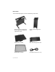
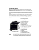
Box Contents The SD2220W shipping box contains the following components: Bottom monitor assembly with mirror support arms and mirror adjustment screws Bottom cable management cover Top monitor assembly Top cable management cover Beamsplitter assembly Two power cords (6-ft and 10-ft) iv | SD2220W
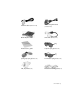
Two Analog VGA cables Two DVI cables (6-ft and 12-ft) (6-ft and 10-ft) Mirror-flip PCI card Short DVI cables (14-in) Product user’s guide Captain-style glasses (2 ea) Spring clip-style glasses (1 ea) Terminator-style glasses (2 ea) Soft, dry cloths (3 ea) Moistened cleaning pads (6 ea) User’s Guide | v
Contents Usage Notice .....................................................................................................................iii Do ......................................................................................................................................iii Don’t .................................................................................................................................iii Box Contents.............................................................................
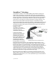
Stereoscopic Viewing We live in a three-dimensional world. The human visual system can process the slightly different views of the world and translate the views into the perception of depth. This process is called stereopsis. In the last two centuries much effort has been devoted to the reproduction of depth perception, primarily with photography and more recently with computer graphic images.
StereoMirror™ Technology A StereoMirror™ monitor consists of two AMLCD (Active Matrix Liquid Crystal Display) units, oriented at a 110º angle and mounted on a specially designed stand. A passive beamsplitter mirror bisects the angle formed between the two monitors, and there is a fine mechanical adjustment for the mirror angle between the two displays. One side of the glass mirror has a reflective coating, and the other side has an anti-reflective coating to minimize secondary reflections.
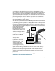
A block diagram describing the process of driving a StereoMirror™ monitor with a computer is shown in the illustration below. The left eye and right eye images are sent to their respective AMLCDs independently and without any special treatment (with the exception of accommodating for the fact that the upper monitor is seen in a mirror; see discussion below). Presenting the stereo pair of images requires a setup or software application that accommodates dual-monitor stereo viewing.
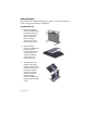
Getting Started Read all instructions before assembling the monitor. Improper assembly can result in damage to the display components. Assemble the unit 1. Remove the bottom monitor assembly from the shipping box and place it on a sturdy table or desktop. To keep the display surface clean, avoid touching the screen. 2. Remove the top monitor assembly from the shipping box. Loosen the two screws on the cover of the cable management compartment and remove the cover. 3.
4. Thread the cables from the top monitor through the rectangular hole in the cross bracket. 5. Replace the top and bottom cable covers, if desired. 6. Remove the beamsplitter from the shipping case. With the StereoMirror™ logo oriented to the lower right, insert the pins located on either side of the mirror frame into the corresponding slots on the mirror support arms. The pins should rest in the fully forward position of the mounting arm slots.
Select a graphics card The SD2220W unit requires a dual-output graphics card to drive the two monitors with a DVI signal. For professional applications that use OpenGL quad-buffered stereo, the graphics card should support OpenGL stereo as well. Typically, the two monitors should be in clone mode for these applications. There are several compatible graphics card families. The NVIDIA Quadro FX line and the Matrox Parhelia line have all been tested and are compatible for OpenGL stereo applications.
Connect the cables The SD2220W unit comes with one 6-foot DVI cable, one 12-foot DVI cable, and one 14-inch DVI cable. 1. Plug one end of the 6-foot DVI cable into the primary port of the dualchannel DVI graphics card. Plug the other end into the bottom monitor of the SD2220W unit. 2. Plug one end of the 14-inch DVI cable into the secondary output of the dual-channel graphics card. Plug the other end into the input port (labeled “IN”) of the mirror-flip PCI card. 3.
Connect the power cords Two power cords shipped with the unit. Use only the power cords supplied with the unit. 1. Plug the 10-foot cord into the AC power jack of the top monitor. Plug the 6-foot cord into the bottom monitor. Then plug the power connectors into a grounded outlet. 2. Turn on the soft power switch located on the front bezel of the two LCD monitors. 3. Power up the computer.
Product Use Operating in 2D mode Your SD2220W unit can operate either as a 3D stereoscopic monitor or in the standard 2D mode. Converting to 2D viewing can be accomplished by either turning off the power to one of the monitors or by putting the mirror into the locked upright position. To move the mirror to the raised position, use two hands to slide it up the mirror support arms and then raise it until it drops into the locked position.
User Controls 1 Power LED will be Green when monitor is on, be yellow when in power saving mode, be dark when monitor in off mode. 2 Power ON/OFF switch. Push to power on or power off.
OSD Menu Main Menu icon Sub Menu item Sub Menu item STANDARD Preset Mode Default Setting. Reflects native display capability. MOVIE Displays scenes in clearest detail. Pictures and photographs appear in vibrant colors with sharp detail. GAME Enhances color. TEXT Optimal balance of brightness and contrast prevent eyestrain. The most comfortable way to read onscreen text PHOTO Enhances colors and emphasize fine detail. Adjusts the background brightness of the screen image.
9300K Sets the color temperature to 9300K. 7500K Sets the color temperature to 7500K. 5000K Sets the color temperature to 5000K. sRGB Sets the color temperature to sRGB. User R/G/B Allows users to adjust red/green/blue intensity. Language Multi-language selection. OSD H. Position Adjusts the horizontal position of the OSD. OSD V. Position Adjusts the vertical position of the OSD. OSD Turn Off Adjusts the OSD timeout.
Power Management This LCD monitor complies with the VESA DPMS (version 1.0) Power Management guidelines. The VESA DPMS provides four power-saving modes through detection of a horizontal or vertical sync signal. When the LCD monitor is in power-saving mode, the monitor screen is blank and the power LED indicator light is amber. Monitor Specifications LCD Panel Size 22W" Display Type Active matrix color TFT LCD Resolution 1680 x 1050 Display Dot 1680 x (RGB) x 1050 Display Color 16.
OSD Brightness Digital Contrast Digital Horizontal Position Digital Vertical Position Digital Phase Digital Clock Digital Display Mode Setup Use EEPROM to save settings in memor. Power Management Mode Power Consumption* AC Input LED Color DPM On 52 W maximum 240 VAC Green DPM Off 2 W maximum 240 VAC Yellow DC switch off Off 1 W maximum 240 VAC Dark Disconnected 2 W maximum 240 VAC *Meeting VESA DPM requirements measured from AC Input end of AC power cord.
Size and weight System width 23.1" (588 mm) System depth 20.7 " (525 mm) System height 24.
System Care Monitors - Turn off the monitors before cleaning. Use a dry, soft cloth, clean room wiper, or compressed air when cleaning the LCD panel surface. A soft cloth moistened with water and/or mild detergent can be used to clean the display housing and stand. Do not touch the LCD panel surfaces with sharp or hard objects. Do not use abrasive cleaners, waxes, or solvents for cleaning. Mirror - Use a dry, soft cloth, clean room wiper, or compressed air when cleaning the mirror surface.
Troubleshooting Problem Possible Solution No image appears on the screen. Check that all the power cord connections are secure. Check that the power buttons on the side and front of both monitors are switched on and that the power indicator light is green. Check that the DVI cables are securely fastened to the graphics card, the mirror-flip PCI card, and the two monitors. Make sure that the pins of the DVI connectors are not bent or broken.
Warning Signals Green power indicator light. Monitor has a signal and is working properly. Amber power indicator light. Monitor is in power-saving mode. LED power indicator is out. Monitor power is off. “Cable Not Connected” message. Monitor is powered on, but is not detecting a video signal. “Input Not Supported” message. The signal of the computer graphics card is not compatible with the LCD monitor.
CRT Recycling If your new Planar monitor is replacing a CRT unit, keep the following in mind: If the CRT unit is in good working condition, consider donating it to a school or nonprofit organization. It may qualify as a charitable tax deduction. Do not throw away a CRT unit. Cathode Ray Tubes contain hazardous materials and cannot be discarded with other refuse. A number of recycling programs are available. Do an online search of “CRT Recycling” for potential service providers in your area.
Planar Customer Service Online Support For support available 24/7, visit our Online Technical Support web page at www.planar.com/support. Online Technical Support is where you can find solutions for common problems, download documentation, view answers to frequently asked questions (FAQs), and get troubleshooting advice. Visit www.planar3d.com for specific questions about configuring the stereo monitor.
Planar Systems, Inc. 1195 NW Compton Drive Beaverton, OR 97006-1992 Customer Service E-mail: planarsupport@planar.com Online: www.planar.