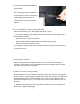
PLANAR LCD TV XP17WSA MANUAL www.planar.
TM-17 User’s Manual Thank you for using our product. This manual explains the use of our TFT LCD product TM-17 and important points. Please read through this manual before use and use as instructed. Please save this manual for future reference. .Built-in TV channel selector for TV viewing.【P18】 .Simultaneous display of PC and TV images.【P19】 .Connectable to PC’s analog RGB port and digital port. .Built-in S-Video, Composite Video, and TV OUT.
Use of Remote Control This product comes with a remote control, which can be used to view TV and switch channels. Please see below for names and functions of control buttons. (Air+CATV) [Tip] Please point the remote control at the receiver of LCD screen during use. ■ About the battery The remote control in the package is not installed with batteries. Please open the case on the back of remote and load the 2 AAA batteries before use.
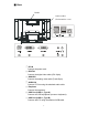
Package Contents Your TFT-LCD package should contain the following items. If any item is missing, please contact your dealer. ● TFT-LCD……………………………………………1 LCD Panel Panel Controls Remote Control Receiver Speakers ● Remote control ...................................................................................... 1 ● Dry-cell battery (AAA) ............................................................................ 2 ● Analog video cable (D-Sub 15 pin) .................................................
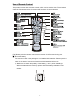
Parts and Functions ■ Front Panel Control Open the Menu Execute Close (restore) OSD menus Mute the speakers Select adjustment item Set value of adjusted item Adjust volume Select adjustment item Select channel Select adjustment item Select channel Switch input Power Symbol OSD MENU MUTE EXIT VOLUME ef + INPUT Function .Access the OSD menus. .Execute the selected option in OSD menu. .Close the OSD menu. .Restore to OSD main menu from sub-menu. .Mute the speakers when OSD menu is not turned on.
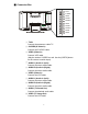
■ Back Handle Connector Box (Underneath the cover) 1 DC-IN ○ Connect the power cord. 2 DIGITAL ○ Connect the digital video cable (DVI 24pin). 3 ANALOG ○ Connect the analog video cable (D-sub15pin). 4 AUDIO-IN ○ Connect PC-Out using the attached audio cable. 5 Earphone ○ Connect the earphone. 6 USB Port (USB1.1; Type A) ○ Connect the USB equipment (mouse or keyboard). 7 USB Port (USB1.1; Type B) ○ Connect with PC using the attached USB cable.
■ Connector Box TV-IN S-VIDEO VIDEO AUDIO L AUDIO R VIDEO AUDIO L AUDIO R AUDIO VIDEO 1 TV-IN ○ Connect the antenna or cable TV. 2 S-VIDEO (S-Video In) ○ Connect the S-VIDEO cable. 3 VIDEO (Video-In) ○ Connect VCR cable. (May be used as S-VIDEO as well. Use the [VIDEO] button on the remote to switch input). 4 AUDIO L (Audio-In (Left)) ○ Connect the stereo audio cable. 5 AUDIO R (Audio-In (Right)) ○ Connect the stereo audio cable. 6 VIDEO (Video-In) ○ Connect the VCR cable.
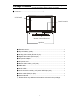
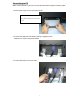
Connecting to PC Make sure the power of your PC is turned off before performing the following steps. 1. Remove the hinge cover on the back of LCD. Push in the direction of arrow and then pull towards you to remove the cover. 2. Connect the attached LCD cables (analog or digital) to LCD. Make sure to use PC-supported cables. 3. Connect the power cord to the LCD.
Watch the stand of LCD when installing the power cord. Be careful that the sharp edges don’t cut your fingers. Caution! Sharp! 4. Connect one end of AC power cord to AC adapter and the other end to the power outlet. 5. Use the attached audio cable to connect the AUDIO-OUT of sound card to AUDIO-IN of LCD. 6. Put the hinge cover back.
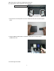
7. Connect the attached USB cable to PC and LCD. The connecting to PC is completed. To connect the LCD to TV antenna or VCR, please see the section of “Connecting to TV Antenna and AV System.” 8. Turn on the power of LCD and the power of PC. When the LCD power is on, the power LED light is in green. ※ The power LED light is in orange and the screen does not have image under the following conditions: . When there is no image from the PC. . When image signals transmitted are not supported by the LCD.
Connecting to TV Antenna / Cable TV and AV System 1. Remove the side cover on the back of LCD. 2. Connect antenna or Cable TV coax wire to TV-IN. 3. Connect the AV equipment (VCR, DVD Player, etc.) to corresponding jacks (S-VIDEO, VIDEO, AUDIO, etc.) 4. Put back the side cover. The connection to TV antenna / Cable TV or AV system is completed.
About the Product ● This TFT-LCD monitor is made by precision technology. It is common to have black spots (lack of pixels) or luminous spots on the panel. Such condition is not a product defect or failure. ● About interfering stripes on the screen (moire pattern) If the screen shows parallel adjoining streaks or latticed pattern in 2~3 colors, it is called the moire pattern. It is the result of interference between luminous colors, not a defect.
● About digital connection Digital connection to some computers, such as Macintosh may result in abnormal display image. In such event, use analog connection. ● About images in TV/VCR mode Some green noises might appear under the following circumstances. This is not an image quality problem. .When TV channel does not have image playing. .When the VCR tape is being forwarded or rewound. Note: Viewing the screen in dark environment or for a long period of time might cause eye fatigue.
Image Adjustment Use OSD function to adjust the image display. About OSD The OSD (On Screen Display) control lets you adjust the image settings. Adjustment can be made using the panel buttons or remote control. ■OSD Main Menu Press the OSD MENU button (or MENU on the remote). The initial OSD menu opened is as shown on the right. The options are indicated by icons. Usee/f( or Å/Æ on the remote) to highlight to desired Main Menu option. Then press the OSD MENU (or MENU on the remote) to open the sub-menu.
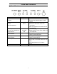
■ OSD Functions in PC Mode (Digital) Menu Basic menus Brightness Contrast Color Color temperature Red (*1) Green (*1) Blue (*1) Sound Volume Treble Bass Balance Mute PC/PIP Others OSD language (*2) OSD horizontal position OSD vertical position Smoothing Zoom Selection of WXGA and XGA (*3) Reset PIP PIP OFF/ON PIP size PIP horizontal position PIP vertical position PIP source Function Adjust the brightness of image. Adjust the contrast of image.
■ On Screen Display (OSD) Functions in PC Mode (Analog) Menu Basic menus Auto adjust Brightness Contrast Phase*(1) Clock (*1) Horizontal position Vertical position Color Color temperature Red (*2) Green (*2) Blue (*2) Sound Volume Treble Bass Balance Mute PC/PIP Others OSD language (*3) OSD horizontal position OSD vertical position Smoothing Zoom Selection of WXGA and XGA Reset PIP PIP OFF/ON PIP size PIP horizontal position PIP vertical position PIP source Function Automatically adjust the image position,
*1 Use manual adjustment only when auto adjust does not bring satisfactory results. *2 Settable only when “User” is selected under “Color Temperature.” *3 The language of OS or applications will not change. About the「sRGB」option under color temperature sRGB is a mode to reproduce the standard color specifications in different computers or monitors. The color displayed in the PC monitor is relative color. When monitor is changed, the image color changes as well.
Auto-Adjust (in case of analog connection only) This product has built-in auto adjust function to obtain the best image display. If the LCD has analog connection, perform auto adjust first. ※ No auto adjust is necessary in case of digital connection. 1. Turn on the power in the sequence of peripherals (including this product) Æ computer. 2. Press the OSD MENU button. OSD Main Menu is displayed. 3. Use e/f button to select the desired “basic setting”, then press OSD MENU again. 4.
TV Viewing This product has built-in TV channel selector. You can watch TV by connecting the antenna to the LCD. Settings for TV Viewing To watch TV, set the channels by performing the following steps: 1. Make sure antenna or cable TV is connected to TV-IN and then turn on the LCD. 2. Press INPUT (or TV on the remote) to switch to TV mode. 3. Press OSD MENU button (or MENU on the remote) to display OSD Main Menu. 4.
Displaying TV or VCR Images on PC Screen You can use PIP (Picture In Picture) function to show TV or VCR images on PC screen. Activate the PIP Function Take the following steps to activate the PIP function: 1. Press INPUT button (or TV on the remote) to switch to TV mode. 2. Press OSD MENU button (or MENU on the remote) to display OSD Main Menu. 3. Use e/f buttons (or Å/Æ on the remote) to select “PIP” option. Then press OSD MENU button (or MENU on the remote) again. 4.
Troubleshooting Refer to the following section if you experience trouble with the product. If the problem persists, please consult our service center. Computer Screen Problems No image appears on screen 1 It might be poor contact between the LCD cable and LCD or Cause ○ graphic card. 2 It might be poor contact of graphic card installed in the computer. Cause ○ 3 It might be poor contact of memory installed in the computer.
Tool bars are not displayed in Windows Cause Bottom of image is outside the display field in Virtual Screen mode. Solution Move the cursor to the bottom of the screen to roll up whole screen 1 for display of tool bars. ○ Solution Lower the resolution setting by the following steps when not using the 2 Virtual Screen mode: ○ 1. Click the right button of mouse on desktop screen and select [Properties (R)] in the menu displayed. 2. In the [Display Properties] dialog, click [Settings] (in case of Windows95/NT4.
If the moire pattern persists after auto adjust, continue on with the following steps: 1. Press OSD MENU button. The OSD Main Menu appears. 2. Use e/f buttons to select [Basic Settings], then press OSD MENU again. 3. Usee/f buttons to select [Clock], then use – or + buttons to change the setting for best display. Adjust to ripple-free state. (Normal display) 4. Use e/f buttons to select [Phase], then use – or + buttons to change the setting for best display. Adjust to noise-free state.
The result is not satisfactory after Auto Adjust. Cause Improper screen display during adjustment. Solution The result of adjustment is influenced by the screen display at the time of adjustment. The best display is the screen with a pattern in 1-dot black and white lattice. Please note that in DOS screen or application screen with more black component, the result of auto adjust is usually not satisfactory.
TV (VCR) Problem Can’t play the TV 1 Incorrect antenna connection. Cause○ 1 Connect the antenna correctly. Solution○ 2 Channels not set correctly. Cause○ 2 Refer to [Settings for TV Viewing](P18) to set channels. Solution○ Can’t hear the sound 1 Incorrect audio cable connection. Cause○ 1 Solution○ Connect the audio cable correctly. 2 Volume is set at the lowest value. Cause○ 2 Refer to [Change the Volume] (P18) for volume adjustment.
Can’t hear any sound 1 Incorrect installation of audio cable. Cause○ 1 Solution○ Install the audio cable correctly. 2 Did not select PIP sound (PC sound was selected). Cause○ 2 Select [PIP] in [PC/PIP] in OSD menu option [Sound]. Solution○ About OSD Function OSD means On Screen Display. It provides the function of showing and adjusting the selected options on the screen. In OSD menu, you can adjust the display size, position, brightness and contrast.
Specifications Panel Resolution (max.) Display area Dot pitch Displayable colors (max.) Luminance (average) Contrast ratio (average) Viewing angle (CR≧ 10) Input signal Input connectors DDC Support frequency USB interface USB connector Power Speaker Power consumption (max.) Dimensions Weight Operating condition 17” wide panel color TFT-LCD W-XGA (1280×768 pixels) 369.6(H) ×221.8(V)mm 0.289(H) ×0.289(V)mm 16.
Compatible Modes The LCD supports the following display modes: Display Mode Resolution Pixel Clock (MHz) VGA VBA(PC-98) VGA VGA VESA VGA VESA VGA VESA SVGA VESA SVGA VESA SVGA VESA SVGA VESA XGA VESA XGA VESA XGA XGA VESA 720p Wide Wide VESA VESA XGA VESA XGA VESA XGA SXGA MAC13" MODE MAC16" MODE MAC19" MODE MAC21" MODE 640×350 640×400 640×480 720×400 640×480 640×480 800×600 800×600 800×600 800×600 1024×768 1024×768 1024×768 1024×768 1152×864 1280×720 1280×768 1280×768 1280×960 1280×1024 1280×1024 128
■ We own the copyright of this manual. Unauthorized reprint, reproduction or alteration of this manual in part or in whole is prohibited. ■ The names of other companies mentioned in this manual are usually the trademark or registered trademark. This manual leaves out symbols such as TW, ®, and ©. ■ The specifications, design and other content of this manual are subject to change for improvement without prior notice. Some descriptions in this manual might differ slightly from the product you have purchased.
This device is a Class II information device that may be used in residential area or neighboring area and in compliance with the VCCI, the EMC standard in Japan. The device might experience reception interference if it is used near locations with broadcasting or TV signal receivers. Use this product correctly according to instructions. This product complies with Class II VCCI specifications. We do not guarantee its performance if it is used incorrectly.
3ODQDU 6\VWHPV ,QF Customer Service Online Support: http://planar.custhelp.com E-mail: desktopmonitors@planar.com Tel: 1-866-PLANAR-1 (1-866-752-6271) Hours: M-F, 8am - 9pm Eastern Time © 2003 Planar Systems, Inc. 04/03 Planar is a registered trademark of Planar Systems, Inc. Other brands and names are the property of their respective owners. Technical information in this document is subject to change without notice.