23x Indoor Speed Dome Camera CAM-ISD48 User’s Manual . User’s manual .
CONTENTS 1. Safety Information..............................................................................4 2. Preface...............................................................................................5 3. Features .............................................................................................6 4. Appearance........................................................................................7 4.2 DIP switches ................................................................
8.2 OSD function List....................................................... 37 8.3 OSD function description........................................... 39 9. Pre-defined System Functions ........................................................ 45 10. Specification................................................................................... 46 . User’s manual .
1. Safety Information Federal Communication Commission (FCC) Statement NOTE: This equipment has been tested and found to comply with the limits of a Class B digital device, pursuant to Part 15 of the FCC Rules. These limits are designed to provide reasonable protection against harmful interference when the equipment is operated in a commercial environment.
2. Preface Congratulations for the purchasing of the world most compact PTZ (Pan, Tilt and Zoom) camera. The camera is designed and manufactured not just to meet the requirements for traditional CCTV and modern digital surveillance, but also increase the systems’ overall performance. This camera line incorporates high resolution color CCD, with two types of lens available: power zoom or vari-focal.
3.
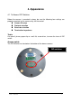
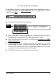
4. Appearance 4.1 To Access DIP Switches Before the camera is mounted in place, be sure the following four settings are properly executed, or the camera may fail the control: Camera ID setup Protocol selection Baud rate selection Termination impedance Tools: Use pencil, pincer, paper clip or small flat screw driver, to move the lever of DIP switch Access points: The DIP switches are located on the bottom of the dome cameras: DIP switches . User’s manual .
4.2 DIP switches Overview of DIP switches There are three sets of DIP switch on board for different setup purposes. location # DS1 DS2 DS3 bit quantity 8 8 2 used for Protocol / baud rate setup Device ID setup Network impedance Refer to the picture on below for DIP switch locations. DS3 DS1 DS2 In the following paragraphs are the detail descriptions of the three main setups the installer must do, before hardware mounting and cabling work should begin. . User’s manual .
4.3 Set Up Device ID Number To build correct network for control communication, every speed dome camera in the network must have an unique ID number, which is set by the bit 1 to 8 of a 8-bit DIP switch DS2.
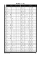
ID table (1 ~ 64) . User’s manual .
ID table (65 ~ 128) . User’s manual .
4.4 Control Protocol and Baud Rate Control protocol and baud rate must be set correctly in the dome camera in order to establish proper control communication between the camera and control device. Be sure that the same protocol and baud rate must be implemented in control device, too. 3 types of protocol and 3 levels of baud rate are provided by this speed dome, through an 8-bit DIP switch labeled DS1. DS 1 remark: 1. 2. 3. 4. 5. 6.
4.5 RS-485 Network and Impedance Transmission distances of RS-485 Bus The 0.56mm (24AWG) twisted pair or higher grade wires are recommended for data transmission cable.
Impedance setup for the speed dome Each speed dome camera has a termination resistor built in. In a network of RS-485 chain, the speed domes are classified in two categories: end unit (such as the #31) and node (such as #1 through #30). To set up the resistor correctly, installer must decide if the specific dome camera is the termination device or not, i.e. if it is at the end of the RS-485 chain. The impedance setup is provided by the bit 1 and bit 2 of DIP switch DS3 .
standards, problems such as signal reflections, lower anti-interference performance arise when the cables are long in the connection. The reliability of control signals could be downgraded with the phenomena that the dome does not respond to or just responds at intervals to the controller, or does continuous operation without stop In such circumstances the usage of RS-485 distributor is recommended.
5. Mount The Speed Dome Camera The camera and its mounting system are designed in modules. There are 5 methods to mount the PTZ camera, which are: 1. 2. 3. 4. 5. Attached to the ceiling surface directly Embedded into ceiling Held to ceiling surface through a bracket (ceiling-drop) Mounted to wall through a bracket Adapted into external housing For all these five mounting ways, a common mounting base for mechanical locking and signal interface shall be adapted as below.
5.1 Mounting Accessory The following items are supplied with the speed dome for the camera mounting. Description 1 Plastic ring The look The Use To hold the camera embedded on ceiling Must be used with the metal ring together to hold the PTZ camera.. 2 Metal ring To hold the camera embedded on ceiling Must be used with the plastic decoration ring together to hold the PTZ camera.
5.2 Surface mount 1. 2. 3. 4. Before installation starts, put mounting base and plastic housing together to make a base module Locate the base module onto the place the camera is to be mounted, and fix the base on the surface completely with screws through the 3 holes on the base (be sure the cables are well located throughout the cable outlet) Get the camera and plug it onto the base; watch for the direction of the connectors on camera and mounting base and be sure they are mated well.
5.3 Embed Camera Into Ceiling Step 1 make holes To insert the speed dome into the ceiling, first a hole must be properly made to let the dome be through for hanging. The best way to decide the diameter of the hole, and the spots for mounting screws, is to use the supplied metal holder.
5.4 Ceiling-drop mount (with CAM-CM) Pre-assembling of the Bowl Module Both ceiling-drop and wall-mount needs to have a bowl module, an assembly of the mounting base and metal bowl supplied in the mounting kit, be built first. Follow the flow chart on below for building up the bowl module. Make a module Put the base into the bowl The mounting base The bowl module Metal bowl To drop camera from ceiling, take the ceiling bracket (option item) and bowl module, 1.
5.5 Wall mount (with CAM-WM) Pre-assembling of the Bowl Module Both ceiling-drop and wall-mount needs to have a bowl module, an assembly of the mounting base and metal bowl supplied in the mounting kit, be built first. Follow the flow chart on below for building up the bowl module. Make a module Put the base into the bowl The mounting base Metal bowl The bowl module Mount the camera on wall To mount camera on wall: 1. 2. 3. 4.
Make it an assembly Put the bowl on bracket The bowl module 5. 6. 7. Locate the assembled piece onto the place the camera is to be mounted, and fix it on the surface completely with screws through the 4 holes on the bracket Get the camera and plug it onto the base; watch for the direction of the connectors on camera and mounting base and be sure they are mated well. Then rotate the camera body counter-clockwise until it is completely locked Put the safety screw (anti-loss) in locking position. .
5.6 Use External Housing (with CAM-OH) To operate speed dome cameras and maintain all functions in normal in severe temperature conditions, i.e. below -10oC or above 45oC, external housing is required. CAM-OH has included two brackets (Ceiling-mount and Wall-mount bracket). You can choose which one you will like to used. Inside the housing, the mounting base (item # 3 in the accessory list) is already built before it leaves factor. (see picture on the right). Wall mount Installation Procedure 1. 2.
4. Put the cables in the trench of bracket, and all connectors come out through the cable outlet. Then put bracket cover and screw back. 5. Load the camera into the housing. Be sure the connectors are well mated and then rotate the camera to lock it in position. 6. Put the safety screw in locking position and tight it. Finished device . User’s manual .
Ceiling mount Installation Procedure 1. Insert the cables pass through the tube. Please also stuff the water proof rub ring into the iron cover on tube. 2. Close the tube onto the outdoor housing and lock it to the housing. Tight them on with screws. 3. Finished. . User’s manual .
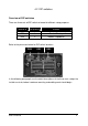
6. Connecting Wires The cables, wires and connector attached to the speed dome are categories into 4 major functions of: 1. 2. 3. 4. Power Video RS-485 Alarm-in and out They are easily distinguished from one to another, as being featured with different connectors. Refer to the picture on below to learn about cable and connector information. 6.1 Power The camera will obtain power source from two kinds of power: DC12V or AC24V. 1.
2. With outdoor housing, AC24V: An AC adapter of 24V / 1.66A is supplied with the outdoor housing (CAM-OH) for the AC version. To power the camera, connect adapter to camera’s power connector.
6.3 RS-485 The camera adapts RS-485 in half-duplex pattern, which is a two-pin connectivity, as shown on the right picture. Installer must pay attention to the polarity of these two pins – yellow wire is the POSITIVE end, and orange is the NEGATIVE. Communication between controller and camera will break and control will not function if they are reversely connected. The RS-485 communication may run for 4,000 feet if the system network is properly built.
The three inputs and their correspondent view presets are independent from one to another. Therefore, with the connections to three sensors, installer can set up camera to monitor three different spots with different dwell time. Presets For Events Default settings at the alarm-ins activations are: If setting(s) is / are done to presets 17, 18 and 19 : At the trigger of alarm-in number 1, lens will move to preset 17. At the trigger of alarm-in number 2, lens will move to preset 18.
Camera is in steady mode when alarm signal(s) kicks in 1. When the first alarm signal hits this camera, lens will move to the corresponding presets (see relative information on above ) at maximum speed of 300o per second 2. Lens will stay at the preset position for 60 seconds 3. Camera will be back to the original position after 60 seconds, if no second alarm-in jumps in this 60 second time frame. 4.
7. Applications The PTZ camera, by itself alone or encompassed in different numbers of domes with comprehensive matrix switching, is mainly for link to 4 different control means (also known in different terms such as controller, console or host): PC-based system Keyboard controller DVR (Digital Video Recorder ) Video server 7.
7.2 Connect single dome to console Connect the RS-485 of camera to controller (such as a keyboard) with a pair of twisted cable. Tele-control is sent via the cable between dome and controller. Video signal from the dome is sent to multiplexer, monitor, DVR or video server directly, normally through coaxial cable (usually the RG-59 A/U). Power (DC12V or AC24V) shall be applied to the camera via separate DC or AC adapter.
Connect Speed dome to standalone DVR Connect the RS-485 of camera to controller (in this case, the DVR) with a pair of twisted cable. Tele-control is conducted from the DVR via the cable between the PTZ device and DVR. Video signal from the dome is sent to DVR also, then forwarded to monitor through the multiplexer inside the DVR. Usually RG59 A/U coaxial cable is recommended for the video connection. Power (DC12V or AC24V) shall be applied to the camera via separate DC or AC adapter.
Connect Speed dome to video server Video server, the contemporary device for transmitting video throughout LAN and WAN, can also be the controlling tool for this speed dome camera. Most video servers in market are built with RS-485 communication port, and single video input for connecting one camera. To work with this PTZ camera, installer must connect both signals (video and RS-485) from the server to the camera, as the picture shown on below.
7.3 Connect two or more domes to console As the RS-485 supports multi-drop topology, two or more domes can be connected to one controller in a system. For such application, the following rules must be kept: All the speed domes should be connected to host in daisy chain pattern. Star type of configuration should be prohibited to avoid system instability. Each dome must have unique ID so communication data can be delivered to the correct target device.
Connect Speed Dome and PC (Capture Card) When PC is used as the console, installer needs to connect both of video and RS-485 signals to PC separately. Most capture cards have 4 video input per card, and normally each PC can handle 4 cards, meaning up to 16 cameras can be hooked to one PC. Video: connect the camera video to the video-in of capture card. RS-485: the RS-485 shall be connected to the RS-232 or USB port through an signal converter.
8. Camera setup --- OSD functions For the version with Power Zoom, many functions are available to users for setup and fine tune through controllers. To access the functions and make adjustment, follow the instructions on below: (NOTE: all the procedure in this paragraph is NOT applied to the version of vari-focal lens) 8.1 OSD operation 1. To initiate the OSD setup function, exercise “preset 88” ( a simulated function call) at keyboard.
OSD functions list (1) 1 Camera ID 2 3 SENSE UP AISHUT 4 AES 5 BLC 6 7 AGC WHITE BAL 8 SYNC 9 10 11 12 ZOOM DIGITAL ZOOM FOCUS AUTO FOCUS 13 POSITION 14 15 16 H-GAIN V-GAIN MOTION 17 IR 18 INITIAL 19 DEFAULT 20 FREEZE 21 FREEZE MODE 22 23 24 ZOOM SPEED FOCUS SPEED GAMMA . User’s manual Off On AUTO. FIX. FIX. AUTO. OFF On ATW. AWB.
8.3 OSD function description 1. Camera ID Î 2 sub-items This is for setting up number or name for camera, providing the convenience to user for distinguishing one camera from others by specific name. Off is not used for putting the number or name on screen. On is for giving the number or name to the camera. Edit: When Edit is selected, the screen of string of 20 characters will be display, ready for alpha-numeric setting.
5. BLC Î On or Off Back-Light-Compensation, a function used for adjusting the exposure level automatically in the conditions that lens is facing strong spot light source, which normally drives AES or AISHUT too much and cause object too dark. Off :To utilize this function, turn it on with the ON/OFF selection firstly On : BLC AREA, make proper mask to block the light source. To do that, 6. 7.
8. SYNC Î On or Off This is to give installer the option of using internal synchronization or external (usually the AC24V). Since this device does NOT work with AC voltage, always keep this in Off mode. 9. Zoom Î 1~23 Times To let user do zoom in and out. Usually this is replaced by hardware buttons on control device 10. Digital Zoom Î On or Off To set up digital zoom function, Factory default setting is OFF. 11. Focus Î To let user make focus adjustment.
Secondly, make proper mask to block the light source. To do that, the target area must be located precisely to cover the target zone. 3rd step is to choose an appropriate sensitivity for the function. This is an important item, and the suggestion is to make test to the sensitivity setting with various moving objects (particularly the size) in different moving speeds, to avoid or reduce unnecessary faulty function.
21. 22. Freeze mode Î Field / Frame To choose whether a field or frame of picture shall be frozen. Zoom speed To choose the zooming speed. If fast zooming is desired, increase the zoom speed. If more accurate image size is required, choose medium or lower speed for zooming. 23. Focus speed To tune focusing speed.
30. MISC Î H-Revers Î On or Off This is for turning picture from left to right, or called “Mirror” To activate it, first enter the “H-reverse”, and choose “ON” in sub-menu. V-Revers Î On or Off This is for turning picture up side down, or called “Flip” To activate it, first enter the “V-reverse”, and choose “ON” in sub-menu. Posi/NEGA Î To change image to positive or negative mode Priority Î is to choose the determining item between AGC (headroom) and sensitivity for internal circuit to follow.
9. Pre-defined System Functions Power-up action After the power is first applied to a dome it will perform a self-test procedure. This calibrates and checks the basic functions of the dome. External controls are overruled during this self-test period. After the self-test, the PTZ camera will be ready for control. If the device was running the Auto-pan function before power was broken, the speed dome will retrieve Auto Scan function until new control is given by an operator.
10. Specification Camera Module and Lens CCD Image control Zoom Manufacturer Resolution Size Optical Digital Focal length Aperture size Light sensitivity Color mode Black / white Pan / Tilt Functions PT driving system Scan / Search Preset Stepping motors Navigation range Navigation speed Preset Search Quantity Dwell time Tour group Auto-pan Communication Protocol Baud rate Camera ID Sony 480 TV lines 1/4” OSD menu 23x 10x 3.6 ~ 82.8 mm F 1.6 ~ 3.8 0.5 lux 0.
Storage Temperature Humidity -20℃ ~ 60℃ 20 ~ 100% RHD Certification Inside the box (Option) Installation Kit . User’s manual FCC, CE Dome camera User’s manual 1 set 1 set Screw Pack 1 set Installation base 1 piece Plastic Housing for surface mount Metal bowl holder 1 piece 1 piece .