30M Infrared Internet Camera ICA-350 User’s Manual Version: 2.00 Date: May.
Copyright Copyright © 2008 by PLANET Technology Corp. All rights reserved. No part of this publication may be reproduced, transmitted, transcribed, stored in a retrieval system, or translated into any language or computer language, in any form or by any means, electronic, mechanical, magnetic, optical, chemical, manual or otherwise, without the prior written permission of PLANET.
Safety This equipment is designed with the utmost care for the safety of those who install and use it. However, special attention must be paid to the dangers of electric shock and static electricity when working with electrical equipment. All guidelines of this and of the computer manufacture must therefore be allowed at all times to ensure the safe use of the equipment. CE Mark Warning This is a Class B product.
Table of Content 1. 2. 3. Introduction ............................................................................................................................. 5 1.1 Overview ......................................................................................................................... 5 1.2 Features............................................................................................................................ 5 1.3 Package Contents..............................................
3.11 E-Mail ............................................................................................................................ 59 3.12 Object Detection ........................................................................................................... 60 3.13 Event Server ................................................................................................................. 61 3.13.1 FTP Server ......................................................................................
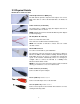
1. Introduction The ICA-350 features zero-lux illumination. The 28 IR illuminator built around the lens brings the clearest vision at night. The ICA-350 offers color vision in day time and monochrome vision at complete darkness environment with built 1/3” color Sony CCD sensor up to 30 meters of distance and use new High-Light LED to provide great performance in the dark and longer LED life. The ICA-350 is water-resistant construction with weatherproof solid housing.
• Motion Detection: the motion detection feature can monitor any suspicious movement in specific area • Supports 2-Way Audio function with hardware version 2 1.3 Package Contents User can find the following items in the package for ICA-350: ICA-350 x 1 Power adapter x 2 Wall mount accessories x 1 Installation software and manual CD x 1 Quick Start Guide x 1 NOTE : 1. If any of the above items are missing, please contact your dealer immediately. 2.
2. Basic Setup This chapter provides details of installing and configuring the ICA-350 2.1 System Requirements Network Interface 10/100MBase-TX Ethernet Monitoring System Recommended for Internet Explorer 6.0 or later Basic System Hardware · CPU: Pentium 4, 3.
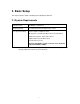
2.2 Physical Details Identification of ICA-350 cables Video Output Connector (BNC port) The ICA-350 also provides composite video output. User can use BNC video cable to connect the ICA-350 with a TV monitor or DVR. Power Connector (for ICA-350) The input power is 12VDC. It supply two adapters that one for heater and the other for camera. NOTE: Supplies the power to the ICA-350 with the power adapter included in package. RS-485 (Black: D- / Red: D+) Connect to a Pan/Tilt scanner unit.
2.3 Hardware Installation 1. Fix ICA-350 to the location with wall mount fixture. 2. Plug-in Ethernet Cable into RJ-45 LAN port. Connect an Ethernet cable to the LAN port on the ICA-350 and connect the other side of the Ethernet cable to a hub/switch. 3. Connect the attached two power adapters to camera and plug-in this two adapters into power outlet. 4. Connect Video BNC connector to a local TV monitor or DVR if necessary. 5. Done. 2.
3. The “Welcome to the InstallShield Wizard for IP Wizard” will display on the screen and click “Next” to continue. 4. Please click “Next” to install with original settings, or you may click “Change…” button to modify the install folder then press “Next” to continue.
5. Please click “Install” to start the installation. 6. Please click “Finish” to complete the installation 7. Please double-click the utility icon utility.
2.5 IP Wizard When you installed the ICA-350 on a LAN environment, you may execute IP Wizard to discover ICA-350’s IP address and set up related parameters in the ICA-350. Search Button: When click Search button, a searching window will pop up. IP Wizard is starting to search ICA-350 on the LAN. The message “No Network Devices Is Found” will appear on this window if IP Wizard cannot find any camera on the LAN. Otherwise, existed cameras will be listed.
Wizard Button: When IP Wizard finds your camera, Wizard button will become available. Please select the device you would like to configure in the Information Box. The device will turn into yellow which means this device is selected; please press “Wizard” button. Or you could double click the mouse left key on the selected camera. Relative settings will be carried out. Details of Install Wizard will be specified as Section 2.6.
2.6 Configure With IP Wizard After pressing Installation Wizard, please key in Username and Password of the device when login dialog box appears on the screen. You can login the setup page if authorized name and password is correct. Default username/password for machine login: admin/ Wizard Page 1: Username and Password This page is about the change of the authorized user name and password of the selected device. If you don’t want to change them, please click “Next” to move to the next page.
Wizard Page 2: LAN Setting This page is about the select of Static IP or DHCP ON. LAN You can configure this ICA-350 to obtain its address automatically or manually assign. If there is a DHCP server in your network environment and you select “DHCP ON”, ICA-350 can automatically obtain an IP address. If you don’t have DHCP server or you want to use fixed IP address, please select “Static IP” and fill in the following fields with proper parameters.
address 192.168.0.20. User may now open your web browser, and key in http://192.168.0.20 in the address bar of your web browser to logon ICA-350’s web configuration page. Wizard Page 3: Confirmation This page shows the new configurations. If it is correct, please press “Submit” icon and the setting information will be save to your ICA-350. Click on “Exit” to close this window.
2.7 UPnP Function NOTE: Windows 2000 does not support UPnP feature. 2.7.1 Windows XP UPnP™ is short for Universal Plug and Play, which is a networking architecture that provides compatibility among networking equipment, software, and peripherals. This device is an UPnP enabled device. If the operating system, Windows XP, of your PC is UPnP enabled, the device will be very easy to configure. Use the following steps to enable UPnP settings only if your operating system of PC is running Windows XP.
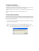
The “Add or Remove Programs” will display on the screen and click Add/Remove Widows Components to continue.
The “Networking Services” will display on the screen, select Universal Plug and Play and click OK to continue.
The program will start installing the UPnP automatically. You will see the below pop-up screen, please wait while Setup configures the components.
Double-click My Network Places on the desktop, the “My Network Places” will display on the screen and double-click the UPnP icon with ICA-350 to view your device in an internet browser. 2.7.2 Windows Vista UPnP™ is short for Universal Plug and Play, which is a networking architecture that provides compatibility among networking equipment, software, and peripherals. This device is an UPnP enabled device.
Double-click My Network Places on the desktop, the “My Network Places” will display on the screen and double-click the UPnP icon with ICA-350 to view your device in an internet browser.
2.8 Setup ActiveX to use the ICA-350 The ICA-350 web pages communicate with the ICA-350 using an ActiveX control. The ActiveX control must be downloaded from the ICA-350 and installed on your PC. Your Internet Explorer security settings must allow for the web page to work correctly. To use the ICA-350, user must setup his IE browser as follows: 2.8.1 Internet Explorer 6 for Windows XP From your IE browse Î ”Tools” Î ”Internet Options…” Î ”Security” ΔCustom Level…”, please setup your “Settings” as follow.
2.8.2 Internet Explorer 7 for Windows XP From your IE browse Î ”Tools” Î ”Internet Options…” Î ”Security” ΔCustom Level…”, please setup your “Settings” as follow. Set the first 3 items • Allow previously unused ActiveX control to run… • Allows Script lets • Automatic prompting for ActiveX controls By now, you have finished your entire PC configuration for ICA-350.
2.8.3 Internet Explorer 7 for Windows Vista From your IE browse Î ”Tools” Î ”Internet Options…” Î ”Security” Î ”Internet” ΔCustom Level…”, please setup your “Settings” as follow. • Enable “Automatic prompting for ActiveX controls” • Prompt “Initialize and script active controls not marked….” From your IE browse Î ”Tools” Î ”Internet Options…” Î ”Security” Î ”Trusted Sites” ΔCustom Level…”, please setup your “Settings” as follow.
3. Web-based Management This chapter provides setup details of the ICA-350’s Web-based Interface. 3.1 Introduction The ICA-350 can be configured with your Web Browser. Before configure, please make sure your PC is under the same IP segment with ICA-350. 3.2 Connecting to ICA-350 z Use the following procedure to establish a connection from your PC to the ICA-350. z Once connected, you can add the ICA-350 to your Browser’s Favorites or Bookmarks.
Web browser may display the “Security Warming” window, select “Yes” to install and run the ActiveX control into your PC. After the ActiveX control was installed and run, the first image will be displayed. NOTE: If you log in the ICA-350 as an ordinary user, setting function will be not available. If you log in the ICA-350 as the administrator, you can perform all the settings provided within the device.
3.3 Live View Start-up screen will be as follow no matter an ordinary users or an administrator. Video Profile ActiveX Control Streaming Protocol Language Setting Menu PTZ Control 2-Way Audio Monitor Image Section De-Interlace Video Information Monitor Image Section The image shot by the ICA-350 is shown here. The date and time are displayed at the top of the window. Video Profile The ICA-350 support multi-profile for both MEPG-4 and M-JPEG simultaneously.
below. : Disable de-interlace function. : Enable de-interlace function. Setting Menu This function is detail setting for ICA-350 that only available for user logged into ICA-350 as administrator. Item Action Network Configure Network settings such as DHCP, DDNS, 3GPP, PPPoE and UPnP Camera Adjust camera parameters System Configure system information, date & time, maintenance, and view system log file.
PTZ Control Click to display the following control panel: Hide PTZ Control Camera Direction Camera Speed Preset Go Tour Tour Auto Pan Hide PTZ Control Click the icon will hide the PTZ control function. Camera Direction Control camera up/down/left/right and home position. Camera Speed Choose the speed of Pan and Tilt. Preset Add/Update the preset positions or go to one of these positions. Tour Select one of the camera tours. Camera tour is comprised by series of preset locations.
3.4 ActiveX Control The plug-in ActiveX control supports a lot of functions by clicking the left mouse button. Note that this feature only supports on the ActiveX control within Microsoft® Internet Explorer. On the ActiveX control icon, click the LeftMouseButton, then a menu pop-up. This menu provides features that are unique to the ActiveX control.
3.4.1 Digital Zoom Click Digital Zoom to active this function as above. User can drag or scale the box over the video to adjust zoom ratio and position. 3.4.2 Record Click Record to activate this function. Press Record button to start recording. The video file is saved as ASF format into your local PC. While you want to stop it, press Stop to stop recording. Select Browser, the pop-up window to select the save path and file name prefix, select OK to continue.
3.4.3 Snapshot Click Snapshot to activate this function. Press Snapshot button to take a picture. The image file is saved as JPEG format into your local PC. Select Browser, the pop-up window to select the save path and file name prefix, select OK to continue. If you like to retrieve the saved image, select the file to display the saved image by using any one of graph editing tools. NOTE: Default save path is “C:\Documents and Settings\All user\Desktop 3.4.
3.4.5 Statistics Click Statistics to activate this function. A window will be popup to show the statistics information of the streaming status. Note that this information is the statistics between the device and your local PC. 3.4.
3.5 Network Use this menu to configure the network to connect the device and the clients. 3.5.1 Network This section provides the menu of connecting the device through Ethernet cable. MAC Address Display the Ethernet MAC address of the device. Note that user cannot change it. Obtain an IP address automatically (DHCP) DHCP: Stands for Dynamic Host Configuration Protocol. Enable this checked box when a DHCP server is installed on the network to issue IP address assignment.
11111111 00000000 will usually be shown in the corresponding, more readable form as 255.255.255.0. Gateway A gateway is a piece of software or hardware that passes information between networks. You'll see this term most often when you either log in to an Internet site or when you're transient email between different servers. Primary DNS When you send email or position a browser to an Internet domain such as xxxxx.com, the domain name system translates the names into IP addresses.
IP address problem comes in the form of a dynamic DNS service. The Internet uses DNS servers to lookup domain names and translates them into IP addresses. Domain names are just easy to remember aliases for IP addresses. A dynamic DNS service is unique because it provides a means of updating your IP address so that your listing will remain current when your IP address changes. There are several excellent DDNS services available on the Internet and best of all they’re free to use.
• Connect to a LAN by DHCP or Fixed IP • Access the device, enter Setting Î Network Î PPPoE as below PPPoE To enable or disable the PPPoE service here. User Name Type the user name for the PPPoE service which is provided by ISP. Password Type the password for the PPPoE service which is provided by ISP. IP Address, Subnet Mask, and Gateway Shows the IP information got from PPPoE server site. Status Shows the Status of PPPoE connection. 3.5.
RTSP Port Choose the RTSP port. The RTSP protocol allows a connecting client to start a video stream. Enter the RTSP port number to use. The default value is 554. RTP Port Specify the range of transmission port number of video stream. The default range is 50000 to 50999. User can specify a number between 1024 and 65535. To use the 3GPP function, in addition to previous section, you might need more information or configuration to make this function work.
traversal when your device is located on an intranet (LAN) and you wish to make it available from the other (WAN) side of a NAT router. With NAT traversal properly configured, all HTTP traffic to an external HTTP port in the NAT router will be forwarded to the device. UPnP To enable or disable the UPnP service here. Friendly Name Shows the friendly name of this device here. UPnP NAT Traversal When enabled, the device will attempt to configure port mapping in a NAT router on your network, using UPnP™.
IP Filter To enable or disable the IP filter function here. IP Filter Policy Choose the filter policy where is denying or allowing. 3.5.7 IP Notification In case the IP address is changed, system is able to send out an email to alert someone if the function is enabled.
SMTP Notification (e-mail) If enable this function, then the “Send to“ and “Subject” field need to be filled. Send To Type the receiver’s e-mail address. This address is used for reply mail. Subject Type the subject/title of the E-mail. TCP Notification If enable this function, then the “TCP Server“, “TCP Port”, and “Message” fields need to be filled. TCP Server Type the server name or the IP address of the TCP server. TCP Port Set port number of TCP server.
Proxy Port Set port number of Proxy. Proxy Login Name Type the user name for the HTTP Proxy. Proxy Login Password Type the password for the HTTP Proxy. Custom Parameter User can set specific parameters to HTTP server. Message The message will be sent to HTTP server.
3.6 Camera Use this menu to set the function of the camera of ICA-350 3.6.1 Picture Brightness Large value will brighten camera. Sharpness Large value will sharpen camera. Contrast Large value will contrast camera heavily. Local Video Output Check this item if a TV or video monitor has been connected to video output of the Network Camera. Un-check it if not any device has been connected.
3.6.2 PTZ Setting PTZ Protocol Type The Network Camera is connected to built-in ICA-350 and controls this device thru RS485 bus. Baud Rate This is the communication speed between network module and ICA-350. Note that please DO NOT changes the default value except on special purpose. If so, user needs to check and set value properly for both sides Camera ID This is the camera ID set in speed dome camera. Note that please DO NOT changes the default value except on special purpose.
3.6.3 Preset Setting This page provides the edit tool to modify or delete the “Preset Setting” item by item. 3.6.4 Tour Setting Up to 64 positions can be preset, and the camera can be programming to move to the preset position sequentially. Tour Name The group name of the sequence of camera tour. The maximum number of camera tour is 16.
Running Enable or disable this camera tour. Preset Set the sequence of the tour. Maximum 16 points can be assigned. The selected preset position is added in the Sequence list from 1 to 16. Wait Time Type a period of time during which the camera is to stay at each preset point, between 0 to 36000 seconds. To use the camera tour function, user must preset some camera positions first. The maximum number of preset points is 64.
3.7 System Use this menu to perform the principal settings of ICA-350. 3.7.1 System Device Title You can enter the name of this unit here. It’s very useful to identify the specific device from multiple units. Software Version This information shows the software version in the device.
3.7.2 Date & Time You can setup the time setting of ICA-350, make it synchronized with PC or remote NTP server. Also, you may select the correct time zone of your country.
Daylight Saving Sets up the date and time of daylight saving stop time. Stop Time Daylight Saving Sets up the date of daylight saving offset. Offset 3.7.3 Maintenance Hard Factory Default (Include the network setting) Recall the device hard factory default settings. Note that click this button will reset all device’s parameters to the factory settings (including the IP address).
3. Disable Motion Detection function. 4. Select “Firmware name” 5. Select the Firmware binary file. (Note that it must make sure that the Firmware only applies to this device, once update, it will be burned into FLASH ROM of system.) 6. Once the firmware file was selected, select “Upgrade”. 7. The upgrade progress information will be displayed on the screen. 8. A message will be shown while the firmware upgraded. Once the upgrading process completed, the device will reboot the system automatically. 9.
3.8 Video This device provides more video profiles as below to support different request to each client simultaneously. Each user can choose his preferred video profile as his request independently. 3.8.1 Common Text Overlay Setting There are some important information can be embedded into image, including date, time, and/or text.
3.8.2 MPEG4/VGA Video Type It’s MPEG4 mode in this profile Resolution It’s VGA mode (640x480) in this profile Bit rate Control Defines the rate control method of this profile. There are two options: Constant Bit Rate (CBR) or Variable Bit Rate (VBR). For CBR, the video bit rate is between 384kbps and 4096kbps. User can set the desired bit rate to match the limitation of bandwidth. For VBR, user should choose the quality level to set the video quality rather than bit rate.
3.8.3 MPEG4/QVGA Video Type It’s MPEG4 mode in this profile. Resolution It’s QVGA mode (320x240) in this profile. Bit rate Control Defines the rate control method of this profile. There are two options: Constant Bit Rate (CBR) or Variable Bit Rate (VBR). For CBR, the video bit rate is between 128kbps and 1024kbps. User can set the desired bit rate to match the limitation of bandwidth. For VBR, user should choose the quality level to set the video quality rather than bit rate.
3.8.4 MPEG4/QQVGA Video Type It’s MPEG4 mode in this profile. Resolution It’s QQVGA mode (160x120) in this profile. Bit rate Control Defines the rate control method of this profile. There are two options: Constant Bit Rate (CBR) or Variable Bit Rate (VBR). For CBR, the video bit rate is between 24kbps and 320kbps. User can set the desired bit rate to match the limitation of bandwidth. For VBR, user should choose the quality level to set the video quality rather than bit rate.
3.8.5 VIDEO/JPEG Video Type It’s JPEG mode in this profile. Resolution User can select VGA, QVGA, or QQVGA mode as the resolution of this JPEG profile. Rate Control The quality level is between 1 and 100. The higher value is the better quality. Max Frame Rate Defines the targeted frame rate of this profile. For example, set the frame rate to 15 fps, then the image will be updated for 15 frames per second. User can set the desired max frame rate versus video quality under the limited bandwidth.
3.
3.10 User Use this menu to set the user names and password of the Administrator and up to 10 users, and access right of each user. Viewer Login User Name Password Verify Password Access Right Add, Update, and Remove Anonymous Choose this to enable anonymous user login. Only users in database Choose this to disable anonymous user login. Enter the user’s new account here which you want. Enter the user’s new password here. Please enter the user’s new password here again to confirm.
3.11 E-Mail You may setup SMTP mail parameters for further operation of Event Schedule. That’s, if users want to send the alarm message out, it will need to configure parameters here and also add at least one event schedule to enable event triggering. SMTP Server Type the SMTP server name or the IP address of the SMTP server. Test Send a test mail to mail server to check this account is available or not. SMTP Port Set port number of SMTP service.
3.12 Object Detection Use this menu to specify motion detection window 1 to window 4 and set the conditions for detection while observing a captured image. Add and Del To add or delete the motion windows. User can specify up to 4 Included and/or Excluded windows to monitor the video captured by this device. By dragging mouse on the image, you can change the position and size of the selected motion window accordingly.
easier to trigger event. Sensitivity Defines the sensitivity value of motion detection. The higher value will be more sensitivity. 3.13 Event Server Setup FTP/TCP/HTTP server configuration 3.13.1 FTP Server You may setup FTP parameters for further operation of Event Schedule. That’s, if users want to send the alarm message to an FTP server, it will need to configure parameters here and also add at least one event schedule to enable event triggering as SMTP.
3.13.2 TCP Server In addition to send video file to FTP server, the device also can send event message to specified TCP server. Name TCP Server TCP Port User can specify multiple TCP servers as wish. Therefore, user needs to specify a name for each TCP server setting. Type the server name or the IP address of the TCP server. Set port number of TCP server.
3.13.3 HTTP Server The device also can send event message to specified HTTP server. Name URL Test HTTP Login Name HTTP Login Password Proxy Address Proxy Login Name Proxy Login Password Proxy Port: User can specify multiple HTTP servers as wish. Therefore, user needs to specify a name for each HTTP server setting. Type the server name or the IP address of the HTTP server. Check the HTTP server whether it is available or not. Type the user name for the HTTP server. Type the password for the HTTP server.
3.14 Event Schedule This menu is used to specify the schedule of Events and activate the some actions provided by this device. Name Name of the Event or Schedule. Enable Enable or disable this Event or Schedule. Type Schedule start with Event trigger or Schedule trigger. Enable Time Trigger by Action Example. NOTE: Define the feasible time slot. Select the triggered sources with event trigger. Define the actions once event triggered.
Appendix A: Reset Factory Default Settings This button is used to restore the factory default settings. Sometimes restarting the ICA-108/108W will make the system back to a normal state. If the system still got problems after reset, user can restore the factory default settings and install it again. Restore the ICA-350: 1. Loosen these two screws. 2.
3. Press and hold the button down continuously. 4. Wait at least 10 seconds and release the button. Then the ICA-350 has been restored to factory default settings and reboot again.
Appendix B: PING IP Address The PING (stands for Packet Internet Groper) command is used to detect whether a specific IP address is accessible by sending a packet to the specific address and waiting for a reply. It’s also a very useful tool to confirm ICA-350 installed or if the IP address conflicts with any other devices over the network. If you want to make sure the IP address of ICA-350, utilize the PING command as follows: z Start a DOS window. z Type ping x.x.x.x, where x.x.x.
Appendix C: Bandwidth and Video Size Estimation The frame rate of video transmitted from the ICA-350 depends on connection bandwidth between client and server, video resolution, codec type, and quality setting of server. Here is a guideline to help you roughly estimate the bandwidth requirements for your ICA-350. The required bandwidth depends on content of video source. The slow motion video will produce smaller bit rate generally and fast motion will produce higher bit rate vice versa.
MPEG4 Resolution Stream setting fps setting Current stream Current fps 640*480 VGA 384Kbps 5 fps 373Kbps - 388Kbps 5 fps 640*480 VGA 1024Kbps 5 fps 1024Kbps - 1036Kbps 5 fps 640*480 VGA 2048Kbps 5 fps around 1800Kbps 5 fps 640*480 VGA 384Kbps 20 fps around 550Kbps 22 fps 640*480 VGA 1024Kbps 20 fps around 1400Kbps 20 fps 640*480 VGA 2048Kbps 20 fps around 2600Kbps 16 - 17fps 320*240 CIF 200Kbps 5 fps 183Kbps - 200Kbps 5 fps 320*240 CIF 1024Kbps 5 fps 760Kbps - 800K
Appendix D: DDNS Application 1. Preface If you have a Cable modem or xDSL, this is a great way to host your own Networked Device or other TCP/IP Service. Get your own domain like www.yourname.com, www.yourname.com.tw etc. (Note: This domain must be registered with Internic via registration authorities such as Network Solutions, DirectNIC, Register.com etc). Your domain name's dynamic IP address is automatically tracked by a DDNS server.
3. Application Steps – DDNS & Domain Name (1). Visit the following web site: http://www.dyndns.org/ (2). Click “Account” (3). After the columns show up at the left side, click “Create Account”.
(4). Fill the application agreement and necessary information. a. Username b. E-mail address and confirmation c. Password and confirmation d.
(5). Check your e-mail mailbox. There will be an e-mail with a title “Your DynDNS Account Information“. Click the hyperlink address to confirm the DDNS service that you just applied. Then DDNS you applied activated. Click to confirm (6). Enter the web page http://www.dyndns.org/ again. Input your username and password that you just applied to login administration interface of DDNS server.
(7). If the correct username and password are input, you can see the following picture at the top-right of the login page. (8). Click the “Services”. (9). Click the “ Dynamic DNS ”. (10). Click the “Create Hosts”.
(11). We could create a domain name without any charge at this step. First, we input the host name. (No.1) Then we pick a domain that is easy to remember. Finally (No.2), click the “Add Host” to submit the domain name information. (No.3) 1 3 2 4. Setup the DDNS and PPPoE of Network Device At last, users have to enter the web page of Networked Device and setup the necessary information of DDNS and PPPoE after the application of DDNS service. Please check the user manual to access the DDNS and PPPoE pages.