8-Port IP Power Manager IPM-8001 IPM-8002 User’s Manual
Copyright Copyright© 2006 by PLANET Technology Corp. All rights reserved. No part of this publication may be reproduced, transmitted, transcribed, stored in a retrieval system, or translated into any language or computer language, in any form or by any means, electronic, mechanical, magnetic, optical, chemical, manual or otherwise, without the prior written permission of PLANET.
Federal Communication Commission (FCC) Radiation Exposure Statement This equipment complies with FCC radiation exposure set forth for an uncontrolled environment. In order to avoid the possibility of exceeding the FCC radio frequency exposure limits, human proximity to the antenna shall not be less than 20 cm(8 inches) during normal operation.
TABLE OF CONTENTS CHAPTER 1 INTRODUCTION .............................................1 1.1 PACKAGE CONTENTS ..............................................................................................................1 1.2 PRODUCT DESCRIPTION..........................................................................................................1 1.3 FEATURES ...............................................................................................................................1 1.
CHAPTER 6 WEB CONFIGURATION ..........................15 6.1 POWER MANAGEMENT .........................................................................................................16 6.1.1 Control............................................................................................................................16 6.1.2 Schedule..........................................................................................................................20 6.2 ENVIRONMENT ........................
Chapter 1 Introduction Thank you for purchasing PLANET IP Power Manager. This manual guides you on how to install and properly use the IP Power Manager in order to take full advantage of its features. 1.1 Package Contents Make sure that you have the following items: z One IP Power Manager z One Power Cord z One User’s Manual and Utility CD z One Quick Installation Guide z One Console Cable z One Rackmount Ear kit z Four Rubber Feet z Four Feet Screw Note: 1.
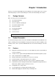
z Upgrade utility for easy firmware upgrade z Event notification through SNMP trap or E-Mail alerts z Daily history report through E-mail z Supports SSL-3 and SSH V1 protocol z Administrator and multiple users with password protection for double-layer security z Address-specific IP security masks to prevent unauthorized access z Available in 110V, 220V and 240V models 1.4 Front and Rear Panel Front Panel IPM-8001 Rear Panel IPM-8002 Rear Panel 1.5 LED And Button on Front Panel 1.5.
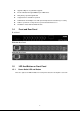
LED Function Current level indicator 1 Description Displays the amount of current being drawn by the connected output device through the power outlet. Displays the out- let power status. Outlet power indicator 2 Off: Power off Green: Power on Displays the remote control status of each outlet. Remote control indicator Off: Remote control is enabled 3 Red: Remote control is disabled Button A 1.5.2 Description Allows manual control of each power outlet.
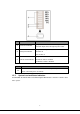
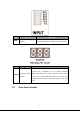
LED INPUT LED Function Description Input power consumption Displays the amount of current being drawn by the indicator connected output device through the power outlet. Function Description Displays input voltage (Volts), input current (Ampere), and frequency (Hz), sequentially on the 7-segment switching STATUS Input power status display. This indicator also shows system errors in the form of indicator an error code such E01, E02, E03, and so on.
Name LAN Function Description Ethernet (LAN) Enables you to connect IP Power Manager to a LAN or port WAN. Enables you to configure the IP Power Manager using the Console Console port serial port. Or you can connect an optional EMD to this port. Sets the mode of operation for the IP Power Manager. S1 Dip-Switch Operation mode DIP switch off and S2 off: Normal operation (default mode).
Chapter 2 Hardware Installation Before you proceed with the installation, it is necessary that you have enough information about the IP Power Manager. 2.1 Connecting Input Power The IP Power Manager has an IEC C20 power inlet for supplying and managing power for the output devices. Connect the power cord to the power inlet and plug the other end into a power outlet as shown: After power connected. You may see the 7-Segment LED display some error messages. If it shows “E01”, please refer to section 2.
2.3 Connecting Digital Outputs The IP Power Manager provides two digital outputs (NO by default) to which you can connect indicators or other output devices that are normally open (NO) or normally closed (NC). The digital output connectors are work as a switch to let you switch the connected device On or Off. The connectors will not provide power to the connected device. So the connected device should connect with its power adapter.
2.5 Connecting The Console You can control the output devices and manage their power status through the console port with serial connection. Use the bundled serial cable to connect the COM port of your PC and the CONSOLE port of the IP Power Manager as shown. Then you can run Hyper Terminal to control and manage your IP Power Manager. 2.6 Connecting LAN or WAN The IP Power Manager has an RJ-45 LAN connector that enables you to monitor and manage the power outlets and digital outputs over the network.
control the IP Power Manager from your PC or laptop. When the network has installed a router, you can also use your mobile phone or PDA that is web browser supported and connected to Internet to control IP Power Manager.
Chapter 3 User Control Button You can turn on power manually for each of the eight output devices with the control buttons provided under each status indicator A through H. Each button allows you to set the remote control function as well as turn power on/off for each outlet manually. The control button has two modes of operation. Press the button repeatedly to switch between Remote Control mode and Power On/Off mode.
Chapter 4 Quick Setup When you are first time configure your IP Power Manager. You may refer to this chapter to know how to initial your IP Power Manager fastest. 1. Please insert User’s Manual and Utility CD into the CD-ROM drive to initiate the autorun program. Once completed a menu screen will appear. 2. Click on “Initial Utility” hyper link to initiate the installation. If the autorun program is not process in your PC, you can click the “Start” button and choose “Run”.
5. In default, IP Power Manager is DHCP client enables. If there is no DHCP server in your network. Please click “Set IP” button. Then enter an IP address that in the same segment of your configuration PC. Please press “OK”. 6. Please press “Browse” button, then you will see a dialog box asking you the user name and password. Please enter “admin” for first time configuration. If you have change the user name and password, please enter correct user name and password of this dialog box. Please press “OK”.
-4-
Chapter 5 Configure With Console The IP Power Manager has provided a serial port that enables you to configure and control the system through your PC’s RS-232 serial (COM) port. Use the serial cable provided to connect the console port to your PC’s COM port as described in “Connecting the console”.
4. The Properties window opens. Click” Restore Defaults” to use the default settings. Make sure that the Bits per second field is set to 9600. Click OK when done. 5. Press any key. The IP Power Manager Configuration Utility Main menu opens and you are prompted for a password. Type the default password (admin) and press Enter to continue. The main menu options are displayed.
6. After enter correct password, you will see the main menu of console interface.
5.2 IP Power Manager Configuration In this option. You can setup the general settings of this IP Power Manager. 5.2.1 System Group In this option. You can change the IP Power Manager IP settings, system date and time. Option Description IP Address The IP address of IP Power Manager is dotted format. Default value is "192.168.0.10", and size is 15 characters. Gateway Address The IP address of the gateway is dotted format. Default value is "0.0.0.0", and size is 15 characters.
5.2.2 Control Group Option Description Administrator In default, the user name is “admin”. You can change the user name to a User Name simply memorize name. Administrator In default, the password is “admin”. Please change the password to IP Password Power Manager in the first time configuration. That can prevent unauthorized user access to IP Power Manager.
standard Telnet port (23). HTTP Control Enable/Disable the HTTP connection with the IP Power Manager. The user may configure HTTP protocol to use a port number other than standard HTTP port (80). SNMP Control Enable/Disable the SNMP connection with the IP Power Manager. The user may configure the SNMP protocol to use a port number other than the standard SNMP port (161). 5.3 Outlets Control In this option, you can select the power outlet and change its settings.
Power on Delay Set power on delay time in seconds. The outlet will turn on after the (Seconds) delay time. Power off Delay Set power off delay time in seconds. The outlet will turn on after the (Seconds) delay time. Output Current Set the upper limit of output current in Amp. Threshold (Amp) Output Current Over If selected, it will turn power off of outlet when this event occurred. Threshold Turn Power Default value is not selected. Off 5.
5.5 Trap Receiver Table This page lists the parameters for SNMP trap receivers (For SNMP Network Management). Option Description IP Address The IP Address in dotted format of the NMS station to which the trap should be sent. Community String The community string of the trap PDU to be sent. The maximum length of the string is 19 characters. NMS-Type Types of the traps to be received. Set the type of the trap. NMS Severity Set the level of the trap to be received.
5.6 Reset Configuration To Default When you would like to reset IP Power Manger to default configuration, please select this option and press “y”. 5.7 Restart IP Power Manager After configuration, please select this option to make the new function works.
5.8 Exit Select this option to exit Hyper Terminal.
Chapter 6 Web Configuration The IP Power Manager provides a graphic user interface that can be viewed from a web browser such as Internet Explorer. This enables you to access and control the IP Power Manager outlets and subsequently, it’s output devices remotely from your desktop, laptop, PDA, or even your mobile phone. This section provides instructions about how to use the web interface to configure and control the IP Power Manager remotely. 1. Open your web browser. 2.
connected), System, Network and Logs. When you click the IP Power Manager front panel on the Home screen. You will see the device status as below. 6.1 Power Management 6.1.1 Control This page shows the rear view of IP Power Manager. While mouse moving over the picture of input, each outlets, or digital output, it will link to its associated page.
6.1.1.1 Inlet This page shows the associated status and even action of inlet. Option Description Status Input Voltage (Volt) The current input voltage in Volt. Input Current (Amp) The current input currents in Amp. Input Frequency (Hz) The current input frequency in Hz. Input Voltage High threshold of input voltage. When input voltage is higher than this Threshold High (Volt) value, IP Power Manager will take action specified in the "Inlet Events Action" table.
Input Voltage Low threshold of input voltage. When input voltage is lower than this Threshold Low (Volt) value, IP Power Manager will take action specified in the "Inlet Events Action" table. Current Event of Inlet Shows the associated event description when there is an event occurred. If there is no event occurred, it shows "None". Inlet Events Action Input Voltage Over Turn off selected outlets or digital outputs will occur when the input Threshold High voltage over high set point.
Power Off Delay Set power off delay time in seconds. The outlet will turn off after the (Seconds) delay time. Output Current Set the upper limit of output current in Amp. Threshold (Amp) Output Current Over If selected, it will turn power off of outlet when this event occurred. Threshold Turn Power Default value is not selected. Off Manual Control Turn On / Turn Off Turn On/Off the outlet immediately by click the buttons. button 6.1.1.
Turn On / Turn Off Turn digital outputs on or off manually. button 6.1.2 Schedule This page allows user to add or remove the IP Power Manager's schedule list dynamically. The maximum schedule is 32. When you would like to add a new schedule, please press “Add New”. Then you will see the screen below. When “Edit” button click, you will also see this screen for edit the existing schedule. If you want to delete the schedule, please press “Delete” button.
Type" is "Special Schedule". Schedule Date Set the date of this schedule. (yyyy/mm/dd) Schedule Time The time in 24-hour format means when the outlet should turn off or (hh:mm) turn on its output power. Outlets Action Set the outlet action to be on or off. IP Power Manager will take action at schedule time. Selected Outlets 6.2 Choose the outlets which you want to turn on or off at schedule time.
Option Description Sensor Name Configure the name of a sensor (or device) with up to 15 characters. Set Point The threshold of a sensor (Temperature or Humidity) will trigger an alarm, whenever the measurement is over (high) or under (low) the set point. If the checkbox is not filled, the threshold is disabled and the alarm will not be triggered. The valid range for the Temperature threshold setting is 5 to 65, and 5 to 95 for Humidity.
EMD Temperature Unit Choose the displayed temperature unit to “Celsius” or “Fahrenheit”. 6.2.3 Alarm This page allows user to modify the parameters associated with the environment events. 6.3 System 6.3.1 Configuration This page contains three groups, “Configure System”, “Administrator Name and Password”, and “Control” group. Configuration of this page is allowed when the security level is “Administrator”.
Option Description Configure System System Name This field allows the user to set the value in System name that is defined in MIB-II or to view the current setting. Size is 31 characters. System Contact This field allows the user to set the value in System manager (System Contact) that is defined in MIB-II or to view the current setting. Size is 31 characters.
Option Description Index This column provides a reference number for the existence user. User Name The user name which is used to log in the IP Power Manager system. Password The password which is used to log in the IP Power Manager system. Outlet Privilege The security level for each outlet. There are two kinds of security level, one is "Read/Write", and the other is "Read".
6.3.3 Date & Time This page provides the appropriate options below to enable the IP Power Manager date/time to be changed in different methods. It will show the current date and time of the IP Power Manager. This can be changed to synchronize with a computer, and enquiry from a time server (NTP) or manually. For the system time, it should be counted automatically. Option Description Current Date and Time IP Power Manager Current date of the IP Power Manager, format is dd/mm/yyyy.
6.3.4 Trap Receivers This page lists the parameters for SNMP trap receivers (For SNMP Network Management). Option Description Index The index number of the entry in the table. NMS IP Address The IP Address in dotted format of the NMS station to which the trap should be sent. Community String The community string of the trap PDU to be sent. The maximum length of the string is 19 characters. Trap Type Types of the traps to be received. Set the type of the trap. [None]: Traps are not be received.
6.3.6 WOL IP Power Manager has support WOL function to wake your PCs up. This function can help your servers work again after the power interruption. Option Description Repeating Times The times of WOL packet IP Power Manager will send. Interval Timer (Sec) The interval between send next WOL packet. Index The index number of the entry in the table. MAC Address MAC address of the PC you would like to wake up. Action You can select Enable or Disable this option.
6.3.7 Email Notification This page is allowed when the security level is “Administrator”. There are two groups in this page, one is “General Configuration” group and the other is “Email Receivers Tables”. Option Description General Configuration Mail Server As Administrator, you may enter the IP Address or Hostname of a SMTP mail server that will be used to send email messages from the IP Power Manager. If entering a Hostname, you are also required to enter the DNS Address.
day in 24-hour format at which time you want the email sent. Email Receivers Tables Mail Account As Administrator, you may enter the email address of the individual you wish to have the IP Power Manager send mail to. Description As Administrator, you may enter a description for reference purposes for each of the Mail Account you configure. As Administrator, you are allowed to select what type of email is sent Mail Type to a specific Mail Account.
Option Description Screen Text This is the description of link name which will display on the menu tree for user's reference. Link Address This field defines the real name of web page to be connected, in URL format. There are two kinds of status, "Enabled", and "Disabled". If the setting Status is "Enabled", the screen text will be shown on the main menu frame. 6.4 Network 6.4.1 Configuration Configuration of this page is allowed when the security level is “Administrator”.
Option Description IP Address The IP address of IP Power Manager is dotted format. Default value is "192.168.1.1", and size is 15 characters. Gateway Address The IP address of the gateway is dotted format. Default value is "0.0.0.0", and size is 15 characters. Subnet Mask The subnet mask of IP Power Manager is dotted format. Default value is "255.255.255.0", and size is 15 characters.
Telnet Connection This is the parameter enabling or disabling the terminal to the server application (Telnet) control process. (e.g. telnet 192.168.1.1). The user may configure the Telnet protocol to use a port number other than the standard Telnet port (23). HTTP Support Enable/Disable the HTTP connection with the IP Power Manager. The user may configure HTTP protocol to use a port number other than standard HTTP port (80). SNMP Support Enable/Disable the SNMP connection with the IP Power Manager.
Access Type 6.5 Available options are: Permitted and Denied. Logs This page gives a snap-shot of all the fundamental IP Power Manager parameters. The Administrator can change consolidation interval by modifying the variable "History Log Interval" in "Configuration of IP Power Manager" page. The existing values are overwritten when the maximum number of entries (rows) has been reached. You can clear the log data in "Clear & Save" menu. 6.5.1 History You will see the history log list in this screen.
Option Description Date (dd/mm/yyyy) This column show the date on which the recording was made. Time (hh:mm:ss) This gives the time in a 24-hour format when the values were recorded. Input Voltage This shows the input voltage in Volts at the time of recording. Input Current This shows the input current in Amps at the time of recording. Input Frequency This shows the input voltage in Hz at the time of recording.
Option Description Date (dd/mm/yyyy) This column show the date on which the recording was made. Time (hh:mm:ss) This gives the time in a 24-hour format when the values were recorded. Event Description 6.5.3 Clear and Save Log Data This screen allows you to clear or save the log file. Option Description Clear Log Data Please select which log you would like to delete and click “Clear” button. Save Log Data You can click the diskette icon to save History or Event log into a file.
Chapter 7 Utility IP Power Manager has provided a utility for customer to set the IP address and upgrade. You can find this utility in “Utility” folder of bundled CD. Buttons Description Device List This will show you all the IP Power manager in your network. Set IP Assign an IP address to IP Power Manager. Browse Open the configuration web page of selected IP Power Manager. Add If the knowing IP Power Manager is not appear in the list, you can add this device to the list manually.
with the located firmware. Open Press this button to locate the firmware. Quit Close utility.
Appendix A Error Code Error Code Description E01 Network link down E02 Parameters checksum error E03 Input voltage over threshold high (Volt) E04 Input voltage over threshold low (Volt) E05 Outlet A current over threshold (Amp) E06 Outlet B current over threshold (Amp) E07 Outlet C current over threshold (Amp) E08 Outlet D current over threshold (Amp) E09 Outlet E current over threshold (Amp) E10 Outlet F current over threshold (Amp) E11 Outlet G current over threshold (Amp) E12 Out
Appendix B Specification Model IPM-8001-US IPM-8002-EU IPM-8002-UK LAN Port 10/100Mbps, RJ-45 Console port RJ-45 connector x 1 COM port 1; For UPS connection Digital Output 2 pair AC Input 110~125V, 15A, 50~60Hz 220V, 15A, 50~60Hz 240V, 13A, 50~60Hz AC Output 110~125V, 15A, 50~60Hz 220V, 15A, 50~60Hz 240V, 13A, 50~60Hz Load 15A for each outlet 10A for each outlet or 10A for each outlet or total 15A total 13A Inlet Connector 1 x IEC 320 C20 Outlet Connector 8 x NEMA 5-15R 8 x IEC 32
Appendix C Glossary Authentication Authentication refers to the verification of a transmitted message's integrity. DHCP DHCP (Dynamic Host Configuration Protocol) software automatically assigns IP addresses to client stations logging onto a TCP/IP network, which eliminates the need to manually assign permanent IP addresses. DNS DNS stands for Domain Name System. DNS converts machine names to the IP addresses that all machines on the net have. It translates from name to address and from address to name.
network. Every client and server station must have a unique IP address. Clients are assigned either a permanent address or have one dynamically assigned to them via DHCP. IP addresses are written as four sets of numbers separated by periods (for example, 211.23.181.189). LAN LANs (Local Area Networks) are networks that serve users within specific geographical areas, such as in a company building.
and forwards mail. SNMP SNMP (Simple Network Management Protocol) is a widely used network monitoring and control protocol. SNMP hardware or software components transmit network device activity data to the workstation used to oversee the network. Subnet Mask Subnet Masks are used by IP protocol to direct messages into a specified network segment (i.e., subnet).