802.
Copyright Copyright 2007 by PLANET Technology Corp. All rights reserved. No part of this publication may be reproduced, transmitted, transcribed, stored in a retrieval system, or translated into any language or computer language, in any form or by any means, electronic, mechanical, magnetic, optical, chemical, manual or otherwise, without the prior written permission of PLANET.
FCC Caution To assure continued compliance (example-use only shielded interface cables when connecting to computer or peripheral devices). Any changes or modifications not expressly approved by the party responsible for compliance could void the user’s authority to operate the equipment. This device complies with Part 15 of the FCC Rules.
Revision User’s Manual for 802.11g Wireless ADSL 2/2+ Router Model: ADW-4401 A/Bv2 Rev: 1.0 (Dec. 2006) Part No.
Table of Contents 1. Introduction…………………………………………………………………………7 1.1 Feature…………………………………………………………………….…….7 1.2 Package Contents………………………………………………………………..8 1.3 Physical Details…………………………………………………………………8 2. Installation…………………………………………………………………………10 2.1 System Requirement…………………………………………………………...10 2.2 Hardware Installation…………………………………………………………..10 2.3 Configuring the Network Properties…………………………………………...11 3. Configuration………………………………………………………………………16 3.
3.7.1.4 DNS Relay……………………………………………………...36 3.8 Wireless Configuration……………………………………………………......36 3.8.1 Wireless Settings……………………………………….……………....36 3.8.1.1 Wireless Security………………………….……………….…...37 3.8.1.2 Advanced Setting…………………………….….…………..….38 3.8.1.3 MAC Address………………………………….……….............39 3.9 Access Management .................................................................................…….39 3.9.1 ACL…….…………………………………………………………..........39 3.9.2 IP Filtering……………………………………………………………….40 3.9.
1. Introduction The PLANET 802.11g Wireless ADSL 2/2+ Router, ADW-4401v2, provides office and residential users the ideal solution for sharing a high-speed ADSL 2/2+ broadband Internet connection on a 54Mbps wireless network and a 10/100Mbps Fast Ethernet backbone. It can support downstream transmission rates of up to 24Mbps and upstream transmission rates of up to 3.5Mbps.
VPN Pass through Support. PCs with VPN (Virtual Private Networking) software using PPTP, L2TP and IPSec are transparently supported - no configuration is required. RIP1/2 Routing. It supports RIP1/2 routing protocol for routing capability. Simple Network Management Protocol (SNMP). It is an easy way to remotely manage the router via SNMP. Wireless Features Standards Compliant. The ADW-4401v2 complies with the IEEE802.11g (DSSS) specifications for Wireless LANs. Maximum of 54Mbps are supported.
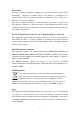
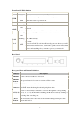
Front Panel LED definition PWR WLAN Description State LED ON When the router is powered on and in ready state OFF When the router is powered off.
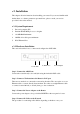
2. Installation This chapter offers information about installing your router. If you are not familiar with the hardware or software parameters presented here, please consult your service provider for the values needed. 2.1 System Requirement 1. Personal computer (PC) 2. Pentium III 266 MHz processor or higher 3. 128 MB RAM minimum 4. 20 MB of free disk space minimum 5. RJ45 Ethernet Port 2.2 Hardware Installation This section describes how to connect and configure the ADW-4401.
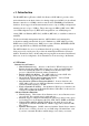
telephone equipment is connected to a POTS splitter. 2.3 Configuring the Network Properties Configuring PC in Windows XP 1. Go to Start / Control Panel (in Classic View). In the Control Panel, double-click on Network Connections 2. Double-click Local Area Connection. 3. In the Local Area Connection Status window, click Properties.
4. Select Internet Protocol (TCP/IP) and click Properties. 5. Select the Obtain an IP address automatically and the Obtain DNS server address automatically radio buttons. 6. Click OK to finish the configuration. Configuring PC in Windows 2000 1. Go to Start / Settings / Control Panel. In the Control Panel, double-click on Network and Dial-up Connections.
2. Double-click Local Area Connection. 3. In the Local Area Connection Status window click Properties. 4. Select Internet Protocol (TCP/IP) and click Properties. 5. Select the Obtain an IP address automatically and the Obtain DNS server address automatically radio buttons. 6. Click OK to finish the configuration.
Configuring PC in Windows 98/Me 1. Go to Start / Settings / Control Panel. In the Control Panel, double-click on Network and choose the Configuration tab. 2. Select TCP/IP -> NE2000 Compatible, or the name of your Network Interface Card (NIC) in your PC. 3. Select the Obtain an IP address automatically radio button. 4. Then select the DNS Configuration tab. 5. Select the Disable DNS radio button and click OK to finish the configuration.
Configuring PC in Windows NT4.0 1. Go to Start / Settings / Control Panel. In the Control Panel, double-click on Network and choose the Protocols tab. 2. Select TCP/IP Protocol and click Properties. 3. Select the Obtain an IP address from a DHCP server radio button and click OK.
3 Configuration 3.1 Determine your connection settings Before you configure the router, you need to know the connection information supplied by your ADSL service provider. 3.2 Connecting the ADSL Router to your network Unlike a simple hub or switch, the setup of the ADSL Router consists of more than simply plugging everything together.
3.3.1 Quick Setup Guide You can use "Quick Setup" to setup the router as follows, and the router will connect to the Internet via ADSL line. Click "Quick Start" to get into the quick setup procedures.
Click "RUN WIZARD" to start up this procedure. Step 1 - Click "Next" to setup your new administrator' s password.
Step 2 - Click "Next" to setup your time zone. Step 3 - Click "Next" to setup your Internet connection type. You can have this information from your Internet Service Provider. Enter the connection information provided by your ISP.
3.4 Maintenance 3.4.1 System Time Go to Maintenance->Time Zone and select system time as you wish. The system time is the time used by the device for scheduling services. You can manually set the time or connect to a NTP (Network Time Protocol) server.
server is set, you will only need to set the time zone. If you manually set the time, you may also set Daylight Saving dates and the system time will automatically adjust on those dates. Current Date/Time: This field displays an updated Date and Time when you reenter this menu. [Time Synchronization] Synchronize time with: You can choose “NTP Server automatically”, “PC’s Clock”, or “Manually” to coordinate the time. Time Zone: Choose the Time Zone of your location.
3.4.2 Admin Setting Go to Maintenance-> Administration to set a new user' s name and password to restrict management access to the router. The default is admin (User's name) and admin (Password) New Password: Type the new password in this field. Confirm Password: Type the new password again in this field. Note: If you ever forget the password to log in, you may press the RESET button up to 6 second to restore the factory default settings.
Current Firmware Version: This filed displays the current firmware version. New Firmware Location: Type in the location of the file you want to upload in this field or click Browse… to find it. UPGRADE: Click UPGRADE to begin the upload process. 3.4.4 SysRestart Go to Maintenance->SysRestart to do system restart. The SysRestart screen allows you to restart your router with either its current settings still in place or the factory default settings.
3.5 Status 3.5.1 Device Info Go to Status->Device Info to check system information. The Device Info screen is a tool that you use to monitor your ADSL Router. It shows the Firmware Version, WAN, LAN, and MAC address information. Note that these fields are read-only and are not meant for diagnostic purposes. Except the Virtual Circuit, click the drop-down list and select the name of the Virtual Circuit on which the system status is to be shown.
[WAN] Virtual Circuit: Click the drop-down list and select the name of the Virtual Circuit on which the system status is to be shown. Status: Connected or Not Connected Connection Type: The WAN Connection Type. IP Address: The WAN port IP address Subnet Address: The WAN port IP subnet mask. Default Gateway: The IP address of the default gateway, if applicable. DNS Server: The IP address of the DNS Server [ADSL] ADSL Firmware Version: This field displays current ADSL firmware version.
3.5.3 Statistics Go to Status-> Statistics and select ADSL or Ethernet interface. The ADSL Router keeps statistic of traffic that passes through it. You are able to view the amount of packets that passes through the Router on both the WAN port & the LAN port. The traffic counter will reset if the device is rebooted. You can select Ethernet/ADSL to view the statistics report of LAN/WAN.
[ADSL] The ADSL screen gives you information about how much data your router has transmitted or received across the ADSL connection. Click on REFRESH to update the screen. 3.6 WAN Configuration 3.6.1 VC Configuration Go to Interface Setup -> Internet. To add or delete ADSL VC configuration, these information provide by ISP. ATM settings are used to connect to your ISP. Your ISP provides VPI, VCI, settings to you.
MBS: Maximum Burst Size (MBS) is the maximum number of cells that can be sent at the PCR. After MBS is reached, cell rates fall below SCR until cell rate averages to the SCR again. At this time, more cells (up to the MBS) can be sent at the PCR again. CBR is for connections that support constant rates of data transfer. The only parameter you need to worry about in CBR is PCR. UBR is for connections that have variable traffic. The only parameter you need to worry about in UBR is PCR.
(1) Dynamic IP Address Select this option if your ISP provides you an IP address automatically. Please enter the Dynamic IP information accordingly. The following table describes the labels in this screen. LABEL DESCRIPTION Encapsulation Select your encapsulation type from the dropdown list. NAT Select whether NAT is Enabled or Disabled. Default Route Select whether this PVC will be the default route for Internet data.
The following table describes the labels in this screen. LABEL DESCRIPTION Encapsulation Select your encapsulation type from the dropdown list. Static IP Address Enter the static IP Address here. IP Subnet Mask Enter the IP Subnet Mask here. Gateway Enter the Gateway address here. NAT Select whether NAT is Enabled or Disabled. Default Route Select whether this PVC will be the default route for Internet data. Dynamic Route Select the RIP type and direction from the dropdown lists.
LABEL DESCRIPTION Username Enter your username for your PPPoE/PPPoA connection. Password Enter your password for your PPPoE/PPPoA connection. Encapsulation Select your encapsulation type from the dropdown list. Bridge Interface Select whether the Interface will be Activated or Deactivated. Connection Select whether your connection is always on or if it connects on demand. If on demand, specify how many minutes the connection may be idle before it disconnects.
Connection Setting: For PPPoE/PPPoA connection, you can select Always on or Connect on-demand. Connect on demand is dependent on the traffic. If there is no traffic (or Idle) for a pre-specified period of time, the connection will tear down automatically. And once there is traffic send or receive, the connection will be automatically on. IP Address: For PPPoE/PPPoA connection, you need to specify the public IP address for this ADSL Router.
(4) Bridge Mode The modem can be configured to act as a bridging device between your LAN and your ISP. Bridges are devices that enable 2 or more networks to communicate as if they are 2 segments of the same physical LAN. Please set the Connection type. The following table describes the labels in this screen. LABEL Encapsulation DESCRIPTION Select your encapsulation type from the dropdown list. 3.7 LAN Configuration 3.7.1 LAN Configuration Go to Interface Setup -> LAN.
3.7.1.1 Router Local IP IP Address: Enter the IP address of your ADSL router in dotted decimal notation, for example, 192.168.1.1 (default setting). IP Subnet Mask: Your ADSL router will automatically calculate the subnet mask based on the IP address that you assign. Unless you are implementing sub netting, use the subnet mask computed by the ADSL router. Dynamic Route: Select the Dynamic Route from RIP1, RIP2-B, and RIP2-M. Please refer to Dynamic Routing. The only difference is the interface. 3.7.1.
LABEL DESCRIPTION Starting IP Address Enter the starting IP address you wish to use as the DHCP server' s IP assignment. IP Pool Count Enter the maximum user pool size you wish to allow. Lease Time Enter the amount of time you wish to lease out a given IP address. DNS Relay Select the DNS relay option you wish to use from the dropdown list. Primary DNS Server Enter the primary DNS server IP address you wish to use. For user discovered DNS only.
3.7.1.4 DNS Relay The DNS Configuration allows the user to set the configuration of DNS. DNS Rely Selection: If user wants to disable this feature, he just needs to set both Primary & Secondary DNS to 0.0.0.0. Using DNS relay, users can setup DNS server IP to 192.168.1.1 on their computer. If not, device will perform as NO DNS relay. If you don’t want to use the DNS Relay option, set the DNS relay to “Use User Discovered DNS Server Only” and set both Primary and Secondary DNS Servers to “0.0.0.0”. 3.
3.8.1.1 Wireless Security WEP (Wired Equivalent Privacy) encrypts data frames before transmitting over the wireless network. Select Disable to allow all wireless computers to communicate with the access points without any data encryption. Select 64-bit WEP or 128-bit WEP to use data encryption. Key#1~Key#4 The WEP keys are used to encrypt data. Both the ADSL Router and the wireless clients must use the same WEP key for data transmission.
3.8.1.2 Advanced Setting Beacon Interval: The Beacon Interval value indicates the frequency interval of the beacon. Enter a value between 20 and 1000. A beacon is a packet broadcast by the Router to synchronize the wireless network. RTS Threshold: The RTS (Request To Send) threshold (number of bytes) for enabling RTS/CTS handshake. Data with its frame size larger than this value will perform the RTS/CTS handshake.
DTIM: This value is between 1 and 255, indicates the interval of the Delivery Traffic Indication Message (DTIM). s 3.8.1.3 MAC Address Filter You can allow or deny a lust of MAC addresses associated with the wireless stations access to the ADSL Router. Status: Use the drop down list box to enable or disable MAC address filtering. Action: Select Deny Association to block access to the router, MAC addresses not listed will be allowed to access the router.
ACL: There has Activated & Deactivated option. The default setting is Deactivated which means all IP can access via router. If you choose Activated, you only can access via router by listed IP addresses. ACL Rule Index: Index number from 1 and up to 16. Active: Once you choose Yes then you can access the IP via router. Application: Each of these labels denotes a service that you may use to remotely manage the Router. Choices are Web, FTP, Telnet, SNMP, Ping, ALL. Interface: Select the access interface.
IP Filter Set Index: The IP Filter Set Index from 1 to 12 and each index can set up to 6 IP Filter. Interface: Choices from PVC0 to PVC7 and LAN. Direction: Choices are Both, Incoming and Outgoing. Select which direction of data flow you wish to apply the filters to. Note that Incoming and Outgoing are from the point of view of your router, relative to the interface you select. For WAN, data coming from outside your system is considered Incoming and data leaving your system is Outgoing.
3.9.3 SNMP Go to Access Management -> SNMP to set SNMP. The Simple Network Management Protocol (SNMP) is used for exchanging information between network devices. It enables a host computer to access configuration, performance, and other system data that resides in a database on the modem. The host computer is called a management station and the modem is called an SNMP agent. The data that can be accessed via SNMP is stored in a Management Information Database (MIB) on the modem.
Get Community: Select to set the password for incoming Get- and GetNext request from management station. Set Community: Select to set the password for incoming Set request from management station. The default password is ‘public’. When you are done making changes, click on SAVE to save your changes. 3.9.4 UPNP Go to Access Management -> UPNP to set UPNP. UPnP (Universal Plug and Play) is a distributed, open networking standard that uses TCP/IP for simple peer-to-peer network connectivity between devices.
UPnP (Universal Plug and Play): You can choose “Activated” or “Deactivated” option from this session. Auto-Configured (by UPnP Application): UPnP network devices can automatically configure network addressing, announce their presence in the network to other UPnP devices and enable exchange of simple product and service descriptions.
Dynamic DNS: Choose the option for Activated or Deactivated DDNS. Service Provider: The default Dynamic DNS service provider is www.dyndns.org. My Host Name: Type the domain name assigned to your ADSL by your Dynamic DNS provider. E-mail Address: Type your e-mail address. Username: Type your user name. Password: Type the password assigned to you. Wildcard support: Select Yes or No to turn on DYNDNS Wildcard. DYNDNS Wildcard --> Enabling the wildcard feature for your host causes *.yourhost.dyndns.
Virtual Circuit (VC): The Virtual Circuit (VC) properties of the ATM VC interface identify a unique path that your ADSL/Ethernet router uses to communicate via the ATM-based network with the telephone company central office equipment. NAT Status: This filed shows the current status of the NAT function for the current VC. Number of IPs: This field is to specify how many IPs are provided by your ISP for current VC. It can be single IP or multiple IPs.
from probing your network. For more information on IP address translation, refer to RFC 1631, The IP Network Address Translator (NAT). Inside/outside indicates where a host is located relative to the ROUTER. The computers hosts of your LAN are inside, while the Web servers on the Internet are outside. Global/local indicates the IP address of a host in a packet as the packet traverses a router.
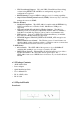
NAT Application The following figure illustrates a possible NAT application, where three inside LANs (logical LANs using IP Alias) behind the router can communicate with three distinct WAN networks. More examples follow at the end of this chapter. NAT Mapping Types NAT supports five types of IP/port mapping. They are: a. One-to-One: In One-to-One mode, the TC3162 EVM maps one local IP address to one global IP address. b.
c. Many-to-Many Overload: In Many-to-Many Overload mode, the TC3162 EVM maps multiple local IP addresses to shared global IP addresses. d. Many-to-Many No Overload: In Many-to-Many No Overload mode, the TC3162 EVM maps each local IP address to a unique global IP address. e. Server: This type allows you to specify inside servers of different services behind the NAT to be accessible to the outside world. The following table summarizes these types.
number. For example, set the FTP Virtual server, you can set the start and end port number to 21. Local IP Address: Enter the IP Address for the Virtual Server in LAN side. Virtual Server Listing: This is a listing of all virtual servers your have set. When you are done making changes, click on SAVE to save your changes, DELETE to delete the rule with the parameters you set, BACK to return to the previous screen or CANCEL to exit without saving. 3.10.1.
When you are done making changes, click on SAVE to save your changes or on BACK to return to the previous screen. 3.10.1.3 IP Address Mapping Go to Advanced Setup ->NAT -> Multiple ->IP Address mapping to set IP Address mapping parameters. The IP Address Mapping is for those VCs that with multiple IPs. The IP Address Mapping rule is per-VC based. (only for Multiple IPs’ VCs). Rule Index: The Virtual server rule index for this VC. You can specify up to 10 rules.
and Many-to Many No-Overload. Local Start & End IP: Enter the local IP address you plan to map to. Local Start IP is the starting local IP address & Local End IP is the ending local IP address. If the rule is for all local IPs, then the Start IP is 0.0.0.0 and the End IP is 255.255.255.255. Public Start & End IP: Enter the Public IP Address you want to do NAT. Public Start IP is the starting Public IP Address and Public End IP is the ending Public IP Address. If you have a Dynamic IP, enter 0.0.0.
3.10.3 Routing 3.10.3.1 Static Routing Go to Advance Setup-> Routing to see the Routing Table Routing Table List This table lists IP address of Internet destinations commonly accessed by your network. When a computer requests to send data to a listed destination, the device uses the Gateway IP to identify the first Internet router it should contact to route the data most efficiently. Select this option will list the routing table information. You can press ADD ROUTE to edit the static route.
IP Subnet Mask: Enter the subnet mask for this destination. Gateway IP Address: Enter the IP address of the gateway. A gateway does the actual forwarding of the packets. Enter the gateway’s IP address in the field or select which PVC you wish to act as a gateway. The gateway is an immediate neighbor of your ADSL Router that will forward the packet to the destination.
RIP-1 is universally supported, but RIP-2 carries more information. RIP-1 is adequate for most networks. Only consider RIP-2 if your network has unusual topology. Both RIP-2B and RIP-2M sends the routing data in RIP-2 format. RIP-2B uses subnet broadcasting while RIP-2M uses multicasting. Direction: Select the RIP direction from None, Both, In Only and Out Only. Multicast: IGMP (Internet Group Multicast Protocol) is a session-layer protocol used to establish membership in a multicast group.
Firewall: Select this option can automatically detect and block Denial of Service (DoS) attacks, such as Ping of Death, SYN Flood, Port Scan and Land Attack. SPI: Select this option to Enabled or Disabled the SPI feature. (NOTE: If you enable SPI, all traffics initiate from WAN would be blocked, including DMZ, Virtual Server, and ACL WAN side) Appendix A: Glossary Address mask A bit mask select bits from an Internet address for subnet addressing.
AWG American Wire Gauge - The measurement of thickness of a wire Bridge A device connects two or more physical networks and forward packets between them. Bridges can usually be made to filter packets, that is, to forward only certain traffic. Related devices are repeaters which simply forward electrical signals from one cable to the other and full-fledged routers which make routing decisions based on several criteria.
Dynamic IP Addresses A dynamic IP address is an IP address that is automatically assigned to a client station (computer, printer, etc.) in a TCP/IP network. Dynamic IP addresses are typically assigned by a DHCP server, which can be a computer on the network or another piece of hardware, such as the Router. A dynamic IP address may change every time your computer connects to the network.
ICMP Internet Control Message Protocol - The protocol handle errors and control messages at the IP layer. ICMP is actually part of the IP protocol. Internet address An IP address is assigned in blocks of numbers to user organizations accessing the Internet. These addresses are established by the United States Department of Defense' s Network Information Center. Duplicate addresses can cause major problems on the network, but the NIC trusts organizations to use individual addresses responsibly.
PAP Password Authentication Protocol PORT The abstraction used in Internet transport protocols to distinguish among multiple simultaneous connections to a single destination host. POTS Plain Old Telephone Service - This is the term describe basic telephone service. PPP Point-to-Point-Protocol - The successor to SLIP, PPP provides router-to-router and host-to-network connections over both synchronous and asynchronous circuits.
Information stored within a router that contains network path and status information. It is used to select the most appropriate route to forward information along. Routing Information Protocol Routers periodically exchange information with one another so that they can determine minimum distance paths between sources and destinations. SNMP Simple Network Management Protocol - The network management protocol of choice for TCP/IP-based Internet.
during your Router' s configuration. Subnet For routing purposes, IP networks can be divided into logical subnets by using a subnet mask. Values below those of the mask are valid addresses on the subnet. TCP Transmission Control Protocol - The major transport protocol in the Internet suite of protocols provides reliable, connection-oriented full-duplex streams. TFTP Trivial File Transfer Protocol.
reality, the data is delivered across a network via the most appropriate route. The sending and receiving devices do not have to be aware of the options and the route is chosen only when a message is sent. There is no pre-arrangement, so each virtual connection exists only for the duration of that one transmission. WAN Wide area network - A data communications network that spans any distance and is usually provided by a public carrier (such as a telephone company or service provider).