Content Security Gateway User’s Manual Content Security Gateway CS-500 User’s Manual
Content Security Gateway User’s Manual Copyright Copyright (C) 2005 PLANET Technology Corp. All rights reserved. The products and programs described in this User’s Manual are licensed products of PLANET Technology, This User’s Manual contains proprietary information protected by copyright, and this User’s Manual and all accompanying hardware, software, and documentation are copyrighted.
Content Security Gateway User’s Manual Table of Contents CHAPTER 1: INTRODUCTION ........................................................................................................................ 1 1.1 FEATURES ........................................................................................................................................................... 1 1.2 PACKAGE CONTENTS ...................................................................................................................
Content Security Gateway User’s Manual 4.3 POLICY OBJECT ................................................................................................................................................ 43 4.3.1 Address ................................................................................................................................................... 43 4.3.1.1 LAN...................................................................................................................................
Content Security Gateway User’s Manual 4.4.4 DMZ To WAN & DMZ To LAN ............................................................................................................ 162 4.5 MAIL SECURITY ............................................................................................................................................... 166 4.5.1 Configure...............................................................................................................................................
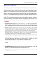
Content Security Gateway User’s Manual Chapter 1: Introduction The innovation of the Internet has created a tremendous worldwide venue for e-business and information sharing, but it also creates network security problems, so the security request will be the primary concerned for the enterprise.
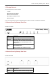
Content Security Gateway User’s Manual 1.2 Package Contents The following items should be included: CS-500 Content Security Gateway User’s Manual CD-ROM This Quick Installation Guide Power Adapter If any of the contents are missing or damaged, please contact your dealer or distributor immediately. 1.3 Content Security Gateway Front View CS-500 Front Panel LED Description PWR Power is supplied to this device. STATUS Blinks to indicate this devise is being turned on and booting.
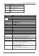
Content Security Gateway User’s Manual settings. WAN Connect to your xDSL/Cable modem or other Internet connection devices LAN Connect to your local PC, switch or other local network device DMZ Connect to your server or other network device 1.5 Specification Product Model Hardware Ethernet Content Security Gateway CS-500 LAN WAN DMZ 1 x 10/100Mbps RJ-45 1 x 10/100Mbps RJ-45 1 x 10/100Mbps RJ-45 LED POWER, STATUS, 10/100 and LNK/ACT for each LAN and WAN port Power 5VDC, 2.
Content Security Gateway User’s Manual IDP QoS User Authentication Logs Statistics Others Anomaly: Syn Flood, UDP Flood, ICMP Flood and more. Pre-defined : Backdoor, DDoS, DoS, Exploit, NetBIOS and Spyware. Custom: User defined based on TCP, UDP, ICMP or IP protocol.
Content Security Gateway User’s Manual Chapter 2: Hardware Installation 2.1 Installation Requirements Before installing the Content Security Gateway, make sure your network meets the following requirements. - Mechanical Requirements The Content Security Gateway is to be installed between your Internet connection and local area network. The Content Security Gateway can be placed on the table or rack. Locate the unit near the power outlet.
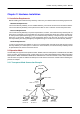
Content Security Gateway User’s Manual The WAN and DMZ side IP addresses are on the same subnet. This application is suitable if you have a subnet of IP addresses and you do not want to change any IP configuration on the subnet. 2.2.2 NAT Mode Connecting Example Internet ISP ADSL Modem CS-500 WAN: 61.11.11.11 LAN: 192.168.1.1 LAN PC 1: 192.168.1.2 DMZ: NAT 192.168.2.1 DMZ PC 3: 192.168.2.2 LAN PC 2: 192.168.1.3 DMZ PC 2: 192.168.2.3 DMZ and WAN IP addresses are on the different subnet.
Content Security Gateway User’s Manual Chapter 3: Getting Started 3.1 Web Configuration STEP 1: Connect both the Administrator’s PC and the LAN port of the Content Security Gateway to a hub or switch. Make sure there is a link light on the hub/switch for both connections. The Content Security Gateway has an embedded web server used for management and configuration. Use a web browser to display the configurations of the Content Security Gateway (such as Internet Explorer 4(or above) or Netscape 4.
Content Security Gateway User’s Manual 3.2 Configure WAN interface After entering the username and password, the Content Security Gateway WEB UI screen will display. Select the Interface tab on the left menu then click on WAN below it. Click on Modify button of WAN, the following page is shown. PPPoE (ADSL User): This option is for PPPoE users who are required to enter a username and password in order to connect. Username: Enter the PPPoE username provided by the ISP.
Content Security Gateway User’s Manual Default Gateway: This will be the Gateway IP address. Domain Name Server (DNS): This is the IP Address of the DNS server. For PPTP (European User Only): This is mainly used in Europe. You need to know the PPTP Server address as well as your name and password. User Name: The user name is provided by ISP. Password: The password is provided by ISP. IP Address: Enter the static IP address assigned to you by your ISP, or obtain an IP address automatically from ISP.
Content Security Gateway User’s Manual Destination Address – select “Outside_Any” Service - select “ANY” Action - select “Permit” Click on OK to apply the changes. STEP 4: The configuration is successful when the screen below is displayed. Please make sure that all the computers that are connected to the LAN port have their Default Gateway IP Address set to the Content Security Gateway’s LAN IP Address (i.e. 192.168.1.1).
Content Security Gateway User’s Manual Chapter 4: Web Configuration 4.1 System The Content Security Gateway Administration and monitoring configuration is set by the System Administrator. The System Administrator can add or modify System settings and monitoring mode. The sub Administrators can only read System settings but not modify them. In System, the System Administrator can: 1. Add and change the sub Administrator’s names and passwords; 2.
Content Security Gateway User’s Manual DHCP: Administrator can configure DHCP (Dynamic Host Configuration Protocol) settings for the LAN (LAN) network. Dynamic DNS: The Dynamic DNS (require Dynamic DNS Service) allows you to alias a dynamic IP address to a static hostname, allowing your device to be more easily accessed by specific name. When this function is enabled, the IP address in Dynamic DNS Server will be automatically updated with the new IP address provided by ISP.
Content Security Gateway User’s Manual Settings of the Administration table Admin Name: The username of Administrators for the Content Security Gateway. The user admin cannot be removed. Privilege: The privileges of Administrators (Admin or Sub Admin) The username of the main Administrator is Admin with read / write privilege. Sub Admin may be created by clicking New Sub Admin. Sub Admin have read only privilege.
Content Security Gateway User’s Manual Removing a Sub Admin Step 1. In the Administration table, locate the Admin name you want to edit, and click on the Remove option in the Configure field. Step 2. The Remove confirmation pop-up box will appear. Click OK to remove that Sub Admin or click Cancel to cancel. 4.1.2 Permitted IPs Only the authorized IP address is permitted to manage the Content Security Gateway.
Content Security Gateway User’s Manual Add Permitted IPs Address Step 1. Click New Entry button. Step 2. In IP Address field, enter the LAN IP address or WAN IP address. Name: Enter the host name for the authorized IP address. IP Address: Enter the LAN IP address or WAN IP address. Netmask: Enter the netmask of LAN/WAN. Ping: Select this to allow the external network to ping the IP Address of the Firewall.
Content Security Gateway User’s Manual 4.1.3 Software Update Under Software Update, the admin may update the device’s software with a newer software. You may acquire the current version number of software in Version Number. Administrators may visit distributor’s web site to download the latest version and save it in server’s hard disk. Step 1. Click Browse to select the latest version of Software. Step 2. Click OK to update software. ÍÍ NOTE: It takes three minutes to update the software.
Content Security Gateway User’s Manual ÍÍ Exporting Content Security Gateway settings Step 1. Under Backup/Restore Configuration, click on the Download button next to Export System Settings to Client. Step 2. When the File Download pop-up window appears, choose the destination place to save the exported file. The Administrator may choose to rename the file if preferred.
Content Security Gateway User’s Manual Importing Content Security Gateway settings Under Backup/Restore Configuration, click on the Browse button next to Import System Settings from Client. When the Choose File pop-up window appears, select the file which contains the saved Content Security Gateway Settings, then click OK. Click OK to import the file into the Content Security Gateway or click Cancel to cancel importing. Restoring Factory Default Settings Step 1.
Content Security Gateway User’s Manual System Name Setting Input the name you want into Device Name column to be the device name. Email Setting Step 1. Select Enable E-mail Alert Notification under E-Mail Setting. This function will enable the Content Security Gateway to send e-mail alerts to the System Administrator when the network is being attacked by hackers or when emergency conditions occur. Step 2. SMTP Server IP: Enter SMTP server’s IP address. Step 3.
Content Security Gateway User’s Manual Web Management (WAN Interface) The administrator can change the port number used by HTTP port1 anytime. (Remote UI Management) Step 1. Set Web Management (WAN Interface). The administrator can change the port number used by HTTP port anytime. MTU (set networking packet length) The administrator can modify the networking packet length. Step 1. MTU Setting. Modify the networking packet length.
Content Security Gateway User’s Manual Dynamic Routing (RIPv2) Enable Dynamic Routing (RIPv2), CS-500 will advertise an IP address pool to the specific network so that the address pool can be provided to the network. You can choose to enable LAN, WAN or DMZ interface to allow RIP protocol supporting. Routing information update timer: CS-500 will send out the RIP protocol in a period of time to update the routing table, the default timer is 30 seconds.
Content Security Gateway User’s Manual To-Appliance Packet Logging When the function is selected, the CS-500 will record the packets that contain the IP address of CS-500 in source or destination, the records will display in Traffic Log for administrator to inquire about. System Reboot Once this function is enabled, the Content Security Gateway will be rebooted. Reboot Appliance: Click Reboot. A confirmation pop-up box will appear.
Content Security Gateway User’s Manual Update system clock every □ minutes You can set the interval time to synchronize with Step 4. outside servers. If you set it to 0, it means the device will not synchronize automatically. Follow this step to sync to your computer’s clock. Step 1. Click on the Sync button. Click OK to apply the setting or click Cancel to discard changes. ÍÍ 4.1.
Content Security Gateway User’s Manual Multiple Subnet settings Click System on the left side menu bar, select Configure then click Multiple Subnet to enter Multiple Subnet window. ÍÍ Multiple Subnet functions WAN Interface IP / Forwarding Mode: Display WAN Port IP address and Forwarding Mode. Interface: Indicate the multiple subnet location in LAN or DMZ site. Alias IP of Int. Interface / Netmask: Local port IP address and subnet Mask. Configure: Modify the settings of Multiple Subnet.
Content Security Gateway User’s Manual Step 1: Find the IP address you want to modify and click Modify. Step 2: Enter the new IP address in Modify Multiple Subnet window. Step 3: Click the OK button below to change the setting or click Cancel to discard changes. Removing a Multiple Subnet Step 1: Find the IP address you want to delete and click Delete. Step 2: A confirmation pop-up box will appear, click OK to delete the setting or click Cancel to discard changes.
Content Security Gateway User’s Manual Sales: Alias IP of LAN interface - 168.85.88.65, Netmask: 255.255.255.192 Procurement: Alias IP of LAN interface - 168.85.88.129, Netmask: 255.255.255.192 Accounting: Alias IP of LAN interface - 168.85.88.193, Netmask: 255.255.255.192 Click System on the left side menu bar, then click Multiple Subnet below Configure menu. Enter Multiple Subnet window.
Content Security Gateway User’s Manual Step 4: Adding a new WAN to LAN Policy. In the Incoming window, click the New Entry button. Modify a Multiple Subnet Routing Mode Step 1: Find the IP address you want to modify in Multiple Subnet menu, then click Modify button, on the right side of the service providers, click OK. Step 2: Enter the new IP address in Modify Multiple Subnet window. Step 3: Click the OK button below to change the setting or click Cancel to discard changes.
Content Security Gateway User’s Manual 4.1.7 Route Table In this section, the Administrator can add static routes for the networks. Entering the Route Table screen Step 1. Click System on the left hand side menu bar, then click Route Table below the Configure menu. The Route Table window appears, in which current route settings are shown. ÍÍ Route Table functions Interface: Destination network, LAN or WAN networks. Destination IP / Netmask: IP address and subnet mask of destination network.
Content Security Gateway User’s Manual Step 4. Click OK to add the new static route or click Cancel to cancel. Modifying a Static Route: Step 1. In the Route Table menu, find the route to edit and click the corresponding Modify option in the Configure field. Step 2. In the Modify Static Route window, modify the necessary routing addresses. Step 3. Click OK to apply changes or click Cancel to cancel it. Removing a Static Route Step 1.
Content Security Gateway User’s Manual 4.1.8 DHCP In the section, the Administrator can configure DHCP (Dynamic Host Configuration Protocol) settings for the LAN (LAN) network. Entering the DHCP window Click System on the left hand side menu bar, then click DHCP below the Configure menu. The DHCP window appears in which current DHCP settings are shown on the screen.
Content Security Gateway User’s Manual Dynamic IP Address functions Subnet: LAN network’s subnet Netmask: LAN network’s netmask Gateway: LAN network’s gateway IP address Broadcast: LAN network’s broadcast IP address Enabling DHCP Support Step 1. In the Dynamic IP Address window, click Enable DHCP Support. Domain Name: The Administrator may enter the name of the LAN network domain if preferred. Automatically Get DNS: Check this box to automatically detect DNS server.
Content Security Gateway User’s Manual ÍÍ Click Dynamic DNS in the System menu to enter Dynamic DNS window. The icons in Dynamic DNS window: !: Update Status, Connecting; Update succeed; Update fail; Unidentified error. Domain name: Enter the password provided by ISP. WAN IP Address: IP address of the WAN port. Configure: Modify dynamic DNS settings. Click Modify to change the DNS parameters; click Delete to delete the settings.
Content Security Gateway User’s Manual Service providers: Select service providers. Sign up: to the service providers’ website. WAN IP Address: IP Address of the WAN port. Automatically : Check to automatically fill in the WAN IP.。 User Name: Enter the registered user name. Password: Enter the password provided by ISP (Internet Service Provider). Domain name: Your host domain name provided by ISP. Click OK to add dynamic DNS or click Cancel to discard changes. Modify dynamic DNS Step 1.
Content Security Gateway User’s Manual 4.1.10 Host Table The Content Security Gateway’s Administrator may use the Host Table function to make the Content Security Gateway act as a DNS Server for the LAN and DMZ network. All DNS requests to a specific Domain Name will be routed to the Content Security Gateway’s IP address. For example, let’s say an organization has their mail server (i.e., mail.planet.com.tw) in the DMZ network (i.e. 192.168.10.10).
Content Security Gateway User’s Manual ÍÍ Below is the information needed for setting up the Host Table: • Host Name: The domain name of the server • Virtual IP Address: The virtual IP address respective to Host Table • Configure: modify or remove each Host Table policy Adding a new Host Table Step 1: Click on the New Entry button and the Add New Host Table window will appear. Step 2: Fill in the appropriate settings for the domain name and virtual IP address.
Content Security Gateway User’s Manual Removing a Host Table Step 1: In the Host Table window, find the policy to be removed and click the corresponding Remove option in the Configure field. Step 2: A confirmation pop-up box will appear, click OK to remove the Host Table or click Cancel. 4.1.11 Language Administrator can configure the Content Security Gateway to select the Language version. Step 1. Select the Language version (English Version, Traditional Chinese Version or Simplified Chinese Version).
Content Security Gateway User’s Manual Step 2. Click Logout the Content Security Gateway. Step 3. Click OK to logout or click Cancel to discard the change. ÍÍ 4.2 Interface In this section, the Administrator can set up the IP addresses for the office network. The Administrator may configure the IP addresses of the LAN network, the WAN network, and the DMZ network. The netmask and gateway IP addresses are also configured in this section. 4.2.
Content Security Gateway User’s Manual IP Address: The private IP address of the Content Security Gateway’s LAN network is the IP address of the LAN port of the device. The default IP address is 192.168.1.1. If the new LAN IP Address is not 192.168.1.1, the Administrator needs to set the IP Address on the computer to be on the same subnet as the Content Security Gateway and restart the System to make the new IP address effective. For example, if the Content Security Gateway’s new LAN IP Address is 172.16.0.
Content Security Gateway User’s Manual Username: Enter the PPPoE username provided by the ISP. Password: Enter the PPPoE password provided by the ISP. IP Address provided by ISP: Dynamic: Select this if the IP address is automatically assigned by the ISP. Fixed: Select this if you were given a static IP address. Enter the IP address that is given to you by your ISP. Max. Upstream/Downstream Bandwidth: The bandwidth provided by ISP.
Content Security Gateway User’s Manual IP Address: The dynamic IP address obtained by the Content Security Gateway from the ISP will be displayed here. This is the IP address of the WAN port of the device. MAC Address: This is the MAC Address of the device. Hostname: This will be the name assign to the device. Some cable modem ISP assign a specific hostname in order to connect to their network. Please enter the hostname here. If not required by your ISP, you do not have to enter a hostname.
Content Security Gateway User’s Manual Ping: Select this to allow the WAN network to ping the IP Address of the Content Security Gateway. This will allow people from the Internet to be able to ping the Content Security Gateway. If set to enable, the device will respond to echo request packets from the WAN network. HTTP: Select this to allow the device WebUI to be accessed from the WAN network. This will allow the WebUI to be configured from a user on the Internet.
Content Security Gateway User’s Manual HTTP: Select this to allow the device WEBUI to be accessed from the WAN network. This will allow the WebUI to be configured from a user on the Internet. Keep in mind that the device always requires a username and password to enter the WebUI. 4.2.3 DMZ The Administrator uses the DMZ Interface to set up the DMZ network. The DMZ network consists of server computers such as FTP, SMTP, and HTTP (web).
Content Security Gateway User’s Manual DMZ Interface: Display DMZ NAT Mode /DMZ TRANSPARENT Mode functions of DMZ to show if they are enabled or disabled. IP Address: The private IP address of the Content Security Gateway’s DMZ interface. This will be the IP address of the DMZ port. If it is in NAT mode, the IP address the Administrator chooses will be a private IP address and cannot use the same network as the WAN or LAN network. NetMask: This will be the subnet mask of the DMZ network.
Content Security Gateway User’s Manual How to use Address Table With easily recognized names of IP addresses and names of address groups shown in the address table, the Administrator can use these names as the source address or destination address of control policies. The address table should be built before creating control policies, so that the Administrator can pick the names of correct IP addresses from the address table when setting up control policies. 4.3.1.1 LAN Entering the LAN window Step 1.
Content Security Gateway User’s Manual If you want to enable Get Static IP address from DHCP Server function, enter the MAC Address then check the Get Static IP address from DHCP Server. Modifying an LAN Address Step 1. In the LAN window, locate the name of the network to be modified. Click the Modify option in its corresponding Configure field. The Modify Address window appears on the screen immediately. Step 2. In the Modify Address window, fill in the new addresses. Step 3.
Content Security Gateway User’s Manual 4.3.1.2 LAN Group Entering the LAN Group window The LAN Addresses may be combined together to become a group. Step 1. Click LAN Group under the Address menu to enter the LAN Group window. The current setting information for the LAN network group appears on the screen. ÍÍ Definitions Name: Name of the LAN group. Member: Members of the group. Configure: Configure the settings of LAN group. Click Modify to change the settings of LAN group.
Content Security Gateway User’s Manual Group. Adding a LAN Group Step 1. In the LAN Group window, click the New Entry button to enter the Add New Address Group window. Step 2. In the Add New Address Group window: Available address: list the names of all the members of the LAN network. Selected address: list the names to be assigned to the new group. Name: enter the name of the new group in the open field. Step 3.
Content Security Gateway User’s Manual Step 2. A window displaying the information of the selected group appears: Available address: list names of all members of the LAN network. Selected address: list names of members which have been assigned to this group. Step 3. Add members: Select names in Available address list, and click the Add>> button to add them to the Selected address list. Step 4.
Content Security Gateway User’s Manual 4.3.1.3 WAN Entering the WAN window Step 1. Click WAN under the Address menu to enter the WAN window. The current setting information, such as the name of the WAN network, IP and Netmask addresses will show on the screen. ÍÍ Definitions Name: Name of WAN network address. IP/Netmask: IP address/Netmask of WAN network. Configure: Configure the settings of WAN network. Click Modify to change the settings of WAN network.
Content Security Gateway User’s Manual Step 2. In the Add New Address window, enter the settings for a new WAN network address. Step 3. Click OK to add the specified WAN network or click Cancel to discard changes. Modifying an WAN Address Step 1. In the WAN table, locate the name of the network to be modified and click the Modify option in its corresponding Configure field. Step 2. The Modify Address window will appear on the screen immediately. In the Modify Address window, fill in new addresses. Step 3.
Content Security Gateway User’s Manual 4.3.1.4 WAN Group Entering the WAN Group window Step 1. Click the WAN Group under the Address menu bar to enter the WAN window. The current settings for the WAN network group(s) will appear on the screen. ÍÍ Definitions: Name: Name of the WAN group. Member: Members of the group. Configure: Configure the settings of WAN group. Click Modify to change the parameters of WAN group Click Remove to delete the selected group.
Content Security Gateway User’s Manual window will appear. Step 2. In the Add New Address Group window the following fields will appear: Name: enter the name of the new group. Available address: List the names of all the members of the WAN network. Selected address: List the names to assign to the new group. Add members: Select the names to be added in the Available address list, and click the Add>> button to add them to the Selected address list.
Content Security Gateway User’s Manual Removing a WAN Group Step 1. In the WAN Group window, locate the group to be removed and click its corresponding Modify option in the Configure field. Step 2. In the Remove confirmation pop-up box, click OK to remove the group or click Cancel to discard changes. 4.3.1.5 DMZ Entering the DMZ window: Click DMZ under the Address menu to enter the DMZ window.
Content Security Gateway User’s Manual Adding a new DMZ Address: Step 1. In the DMZ window, click the New Entry button. Step 2. In the Add New Address window, enter the settings for a new DMZ address. Step 3. Click OK to add the specified DMZ or click Cancel to discard changes. Modifying a DMZ Address: Step 1. In the DMZ window, locate the name of the network to be modified and click the Modify option in its corresponding Configure field. Step 2.
Content Security Gateway User’s Manual Removing a DMZ Address: Step 1. In the DMZ window, locate the name of the network to be removed and click the Remove option in its corresponding Configure field. Step 2. In the Remove confirmation pop-up box, click OK to remove the address or click Cancel to discard changes. 4.3.1.6 DMZ Group Entering the DMZ Group window Click DMZ Group under the Address menu to enter the DMZ window. The current settings information for the DMZ group appears on the screen.
Content Security Gateway User’s Manual Adding a DMZ Group: Step 1. In the DMZ Group window, click the New Entry button. Step 2. In the Add New Address Group window: Available address: list names of all members of the DMZ. Selected address: list names to assign to a new group. Step 3. Name: enter a name for the new group. Step 4. Add members: Select the names to be added from the Available address list, and click the Add>> button to add them to the Selected address list. Step 5.
Content Security Gateway User’s Manual Modifying a DMZ Group: Step 1. In the DMZ Group window, locate the DMZ group to be modified and click its corresponding Modify button in the Configure field. Step 2. A window displaying information about the selected group appears: Available address: list the names of all the members of the DMZ. Selected address: list the names of the members that have been assigned to this group. Step 3.
Content Security Gateway User’s Manual Removing a DMZ Group: Step 1. In the DMZ Group window, locate the group to be removed and click its corresponding Remove option in the Configure field. Step 2. In the Remove confirmation pop-up box, click OK to remove the group. 4.3.2 Service In this section, network services are defined and new network services can be added. There are three sub menus under Service which are: Pre-defined, Custom, and Group.
Content Security Gateway User’s Manual and the server port ranges from 0 to 1023. How do I use Service? The Administrator can add new service group names in the Group option under Service menu, and assign desired services into that new group. Using service group the Administrator can simplify the processes of setting up control policies. For example, there are 10 different computers that want to access 5 different services on a server, such as HTTP, FTP, SMTP, POP3, and TELNET.
Content Security Gateway User’s Manual Step 1. Click Custom under it. A window will appear with a table showing all services currently defined by the Administrator. ÍÍ Definitions: Service name: The defined service name. Protocol: Network protocol used in the basic setting. Such as TCP、UDP or others. Client port: The range of Client port in defined service. If the number of ports entered in the two fields of Client port is different, it means that the port numbers between these two numbers are opened.
Content Security Gateway User’s Manual Modifying Custom Services Step 1. A table showing the current settings of the selected service appears on the screen Step 2. Enter the new values. Step 3. Click OK to accept editing; or click Cancel. Removing Custom Services Step 1. Click its corresponding Remove option in the Configure field. Step 2. In the Remove confirmation pop-up box, click OK to remove the selected service or click Cancel to cancel action.
Content Security Gateway User’s Manual 4.3.2.3 Group Accessing the Group window Step 1. Click Group under it. A window will appear with a table displaying current service group settings set by the Administrator. ÍÍ Definitions: Group name: The Group name of the defined Service. Service: The Service item of the Group. Configure: Configure the settings of Group. Click Modify to change the parameters of the Group. Click Remove to delete the Group.
Content Security Gateway User’s Manual Step 3. Enter the new group name in the group Name field. This will be the name referencing the created group. Step 4. To add new services: Select the services desired to be added in the Available service list and then click the Add>> button to add them to the group. Step 5. To remove services: Select services desired to be removed in the Available service, and then click the <
Content Security Gateway User’s Manual Removing Service Groups In the Remove confirmation pop-up box, click OK to remove the selected service group or click Cancel to cancel removing. 4.3.3 Schedule The Content Security Gateway allows the Administrator to configure a schedule for policies to take affect. By creating a schedule, the Administrator is allowing the Content Security Gateway policies to be used at those designated times only.
Content Security Gateway User’s Manual The following items are displayed in this window: Name: the name assigned to the schedule Configure: modify or remove Adding a new Schedule Step 1. Click on the New Entry button and the Add New Schedule window will appear. Schedule Name: Fill in a name for the new schedule. Period: Configure the start and stop time for the days of the week that the schedule will be active. Step 2.
Content Security Gateway User’s Manual Step 1. In the Schedule window, find the policy to be modified and click the corresponding Modify option in the Configure field. Make needed changes. Step 2. Click OK to save changes. Removing a Schedule Step 1. In the Schedule window, find the policy to be removed and click the corresponding Remove option in the Configure field. Step 2. A confirmation pop-up box will appear, click on OK to remove the schedule. 4.3.
Content Security Gateway User’s Manual Configuration of QoS Click QoS in the menu bar on the left hand side. ÍÍ Definitions: Name: The name of the QoS you want to configure. WAN: Display WAN interface. Downstream Bandwidth: To configure the Guaranteed Bandwidth and Maximum Bandwidth. Upstream Bandwidth: To configure the Guaranteed Bandwidth and Maximum Bandwidth. Priority: To configure the priority of distributing Upstream/Downstream and unused bandwidth. Add New QoS Step 1.
Content Security Gateway User’s Manual Modify QoS Step 1. Click QoS in the menu bar on the left hand side. Click the Modify button to modify QoS. Definition: Name: The name of the QoS you want to configure. Downstream Bandwidth: To configure the Guarateed Bandwidth and Maximum Bandwidth. Upstream Bandwidth: To configure the Guarateed Bandwidth and Maximum Bandwidth. QoS Priority: To configure the priority of distrubuting Upstream/Downstream and unused bandwidth. Click the OK button to modify QoS.
Content Security Gateway User’s Manual Step 2. Configure the LAN host or WAN host IP address that need to filter with QoS feature. Be aware that the Netmask must set to 255.255.255.255 if you only want to configure a single IP address. Step 3. Set up the QoS rule.
Content Security Gateway User’s Manual Step 4. Enable the QoS rule in Outgoing or Incoming Policy. 4.3.5 Authentication By configuring the Authentication, you can control the user’s access right time of LAN to WAN. The administrator can configure the authentication according to the authentication account and password. CS-500 configures the authentication of LAN’s user by setting account and password to identify the privilege. 4.3.5.
Content Security Gateway User’s Manual Authentication Port: The port number used for user login page. Generally, when user want to access WAN network and the authentication (Policy -> Outgoing) is enabled, the user only need to open a web page and the User Login page will pop up.
Content Security Gateway User’s Manual Definitions: Name:The name of the Authentication you want to configure. Configure: modify settings or remove users. Adding a new Auth User Step 1. In the Authentication window, click the New User button to create a new Auth User. Step 2. In the Auth-User window: Auth-User Name: enter the username of new Authentication. Password: enter a password for the new Authentication. Confirm Password: enter the password again. Step 3.
Content Security Gateway User’s Manual NOTE: When the LAN user access to WAN network and do not use for a while, the connection will be time-out. User has to re-login again. The default time is 30 minutes and you can configure this time by “Authentication”-> “Auth Setting” page. In the form of controlling the [Outgoing] Policy, enable the Authentication-User Function. User Login Page Definitions: User Name: The name of the Authentication you want to configure.
Content Security Gateway User’s Manual Modifying the Authentication User Step 1. In the Authentication window, locate the Auth-User name you want to edit, and click on Modify in the Configure field. Step 2. The Modify Auth-User Password window will appear. Enter in the required information: Auth-User: show original authentication user. Password: show original password. New Password: enter new password Confirm Password: enter the new password again. Step 3.
Content Security Gateway User’s Manual 4.3.5.3 Auth Group Accessing the Auth Group window Click Authentication in the menu bar on the left hand side of the window. Click Auth Group under it. A window will appear with a table displaying current Auth Group settings by the Administrator. Adding Auth Group Step 1. In the Auth Group window, click the New Entry button. In the Auth Group window, the following fields will appear: Name: Enter the new Auth Group name.
Content Security Gateway User’s Manual Modifying Auth Group Step 1. In the Auth Group window, locate the Auth Group to be edited. Click its corresponding Modify option in the Configure field. In the Modify Auth group window the following fields are displayed:: Step 2. Step 3. Name: Enter the new Auth Group name . Available auth user: List all the available Auth User. Selected auth user: List Auth User to be assigned to the new group.
Content Security Gateway User’s Manual Removing Auth Group Step 1. In the Auth Group window, locate the Auth Group to be removed and click its corresponding Remove option in the Configure field. Step 2. In the Remove confirmation pop-up box, click OK to remove the selected service group or click Cancel to cancel removing. 4.3.5.4 Radius Serve Click Authentication on the left side menu bar, then click Radius Server below it. The following window is shown.
Content Security Gateway User’s Manual Definition ♦ Enable RADIUS Server: Enable RADIUS Server Authentication. ♦ RADIUS Server IP: Enter RADIUS Server IP address. ♦ RADIUS Server Port: Enter RADIUS Server Port. The default port is 1812. ♦ Shared Secret: The Password for CS-500 to access RADIUS Server. ♦ Enable 802.1x RADIUS Server Authentication: Enable 802.1x RADIUS Server Authentication. 4.3.5.5 POP3 Click Authentication on the left side menu bar, then click POP3 below it.
Content Security Gateway User’s Manual 4.3.6 Content Blocking Content Blocking includes “URL”, “Scripts”, “P2P”, “IM”, “Download” and “Upload”. URL: The administrator can use a complete domain name or key word to make rules for specific websites. Scripts : To let Popup、ActiveX、Java、Cookie in or keep them out. P2P : Block P2P program, include “eDonkey”, “Bit Torrent“ and “WinMX”. IM : Block Internet Message program, include “MSN”, “Yahoo Messenger”, “ICQ”, “QQ” and “Skype”.
Content Security Gateway User’s Manual Configure: To change the settings of URL Blocking, click Modify to change the parameters; click Delete to delete the settings. Adding a URL policy Step 1. After clicking New Entry, the Add New URL String window will appear. Step 2. Enter the URL of the website to be blocked. Step 3. Click OK to add the policy. Click Cancel to discard changes. Modifying a URL String Policy Step 1.
Content Security Gateway User’s Manual Step 1. In the URL window, find the policy to be removed and click the corresponding Remove option in the Configure field. Step 2. A confirmation pop-up box will appear, click on OK to remove the policy or click on Cancel to discard changes. 4.3.6.2 Scripts To let Popup, ActiveX, Java, or Cookies in or keep them out. Step 1: Click Scripts below Content Blocking menu. Step 2: Select Scripts detective functions: Popup Blocking: Prevent pop-up boxes from appearing.
Content Security Gateway User’s Manual ÍÍ When the system detects the setting, the Content Security Gateway will spontaneously work. 4.3.6.3 P2P Step 1: Click P2P below Content Blocking menu. Step 2: Select P2P detective functions: eDonkey Blocking: Prevent eDonkey connection built up. Bit Torrent Blocking: Prevent Bit Torrent connection built up. WinMX Blocking: Prevent WinMX connection built up. Step 3: After selecting each function, click the OK button below.
Content Security Gateway User’s Manual will display at the top side. 4.3.6.4 IM Step 1: Click IM below Content Blocking menu. Step 2: Select IM detective functions: MSN Messenger Blocking: To select to block MSN Messenger login, File Transfer, Voice or Camera transferring. Yahoo Messenger Blocking: To select to block Yahoo Messenger login, File Transfer, Voice or Camera transferring. ICQ Blocking: Only to select to block ICQ login. QQ Blocking: Only to select to block ICQ login.
Content Security Gateway User’s Manual ÍÍ 4.3.6.6 Upload Step 1: Click Upload below Content Blocking menu. Step 2: Select Upload detective functions: All Types Block: To block all types of the files uploading from web page. Audio and Video Types block: To block audio and video uploading from web page.. Extensions Block: To block specific extensions name of the files from web page. Step 3: After selecting each function, click the OK button below. 4.3.
Content Security Gateway User’s Manual assigns each computer a private IP address, and converts it into a real IP address through Content Security Gateway’s NAT (Network Address Translation) function. If a server providing service to the WAN networks is located in the LAN networks, outside users can’t directly connect to the server by using the server’s private IP address. The Content Security Gateway’s Virtual Server can solve this problem.
Content Security Gateway User’s Manual address of the WAN network, and the real IP is translated to a private IP of the LAN network. Mapped IP and Virtual Server are the two methods to translate the real IP into private IP. Mapped IP maps IP in one-to-one fashion; that means, all services of one real WAN IP address is mapped to one private LAN IP address. Entering the Mapped IP window Step 1. Click Mapped IP under the Virtual Server menu bar and the Mapped IP configuration window will appear.
Content Security Gateway User’s Manual Modifying a Mapped IP Step 1. In the Mapped IP table, locate the Mapped IP you want it to be modified and click its corresponding Modify option in the Configure field. Step 2. Enter settings in the Modify Mapped IP window. Step 3. Click OK to save change or click Cancel to cancel. NOTE: A Mapped IP cannot be modified if it has been assigned/used as a destination address of any Incoming policies. Removing a Mapped IP Step 1.
Content Security Gateway User’s Manual 4.3.7.2 Virtual Server Virtual server is a one-to-many mapping technique, which maps a real IP address from the WAN interface to private IP addresses of the LAN network. This function provides services or applications defined in the Service menu to enter into the LAN network. Unlike a mapped IP which binds a WAN IP to a LAN IP, virtual server binds WAN IP ports to LAN IP ports.
Content Security Gateway User’s Manual Configure: To change the service configuration, click Configure to change the parameters; click Delete to delete the configuration. This virtual server provides four real IP addresses, which means you can setup four virtual servers at most.
Content Security Gateway User’s Manual Removing a Virtual Server Step 1. Click the virtual server to be removed in the corresponding Virtual Server option under the Virtual Server menu bar. A new window displaying the virtual server’s IP address and service appears on the screen. Step 2. Click the Virtual Server’s IP Address button at the top of the screen. Step 3. Delete the IP address. Step 4. Click OK to remove the virtual server. Setting the Virtual Server’s services Step 1.
Content Security Gateway User’s Manual Server (Load Balance Server). External Service Port: Input the port number that the virtual server will use. Changing the Service will change the port number to match the service. Load Balance Server: The internal server IP address mapped by the virtual server. Four computer IP addresses can be set at most, and the load can be maintained in a balance by round robin algorithm. Step 3.
Content Security Gateway User’s Manual Virtual Server Real IP: displays the WAN IP address assigned to the Virtual Server Service (Port): select the service from the pull down list that will be provided by the Real Server (Load Balance Server). External Service Port: Input the port number that the virtual server will use. Changing the Service will change the port number to match the service. Load Balance Server: The internal server IP address mapped by the virtual server.
Content Security Gateway User’s Manual Click OK to execute the change of the virtual server, or click Cancel to discard changes. NOTE: If the destination Network in Policy has set a virtual server, it will not be able to change or configure this virtual server, you have to remove this configuration of Policy, and then you can execute the modification or configuration. Removing the Virtual Server service Step 1.
Content Security Gateway User’s Manual 4.3.8 VPN The CS-500 adopts VPN to set up safe and private network service, and combine the remote Authentication system in order to integrate the remote network and PC of the enterprise. It also provides the remote users a safe encryption way to have best efficiency and encryption when delivering data. CS-500 provides two kinds of VPN service and the PPTP client. IPSec Autokey: The system manager can create a VPN connection using Autokey IKE.
Content Security Gateway User’s Manual The fields in the IPSec Autokey window are: Name: The VPN name to identify the VPN tunnel definition. The name must be different for the two sites creating the tunnel. Gateway IP: The other side WAN interface IP address of VPN Gateway. IPSec Algorithm: The display the Algorithm way. Configure: Modify and Delete. Adding the Autokey IKE Step 1: Click the New Entry button and the VPN Auto Keyed Tunnel window will appear.
Content Security Gateway User’s Manual Remote Gateway or Client – Dynamic IP: Select Remote Gateway or Client if there is only one user or device and dials up to Internet with PPPoE or cable modem. Preshared Key: The IKE VPN must be defined with a Preshared Key. The Key may be up to 128 bytes long. Encapsulation ISAKMP Algorithm ENC Algorithm: ESP Encryption Algorithm. ESP (Encapsulating Security Payload) provides security for the payload (data) sent through the VPN tunnel.
Content Security Gateway User’s Manual My ID/Peer ID: My ID and Peer ID are optional parameters. If we choose to enter My ID/ Peer ID, they couldn’t be the same. For instance, My ID is 11.11.11.11 and Peer ID is 22.22.22.22. If you want to use number or text, add @ in the front, for instance, @123A and @abcd123. GRE/IPSec: Select GRE/IPSec (Generic Routing Encapsulation) packet seal technology. You may enter IP to be identified for both VPN gateways.
Content Security Gateway User’s Manual Disable PPTP: Check to disable PPTP Server. Enable PPTP: Check to enable PPTP Server. Encryption: the default is set to disabled. Client IP Range: Enter the IP range allocated for PPTP Clients when they connect to the PPTP server. Allow remote client to connect to Internet: Check to allow remote PPTP client accessing Internet via PPTP tunnel.
Content Security Gateway User’s Manual Step 3. Click OK to save modifications or click Cancel to cancel modifications. Modifying PPTP Server Step 1. Select VPN→PPTP Server. Step 2. In the PPTP Server window, find the PPTP server that you want to modify. Click Configure and click Modify. Step 3. Enter appropriate settings. Step 4. Click OK to save modifications or click Cancel to cancel modifications Removing PPTP Server Step 1. Select VPN→PPTP Server. Step 2.
Content Security Gateway User’s Manual 4.3.8.3 PPTP Client This function allows the Content Security Gateway dial-up to remote PPTP server and accesses the network resources on remote network. Entering the PPTP Client window Step 1. Select VPN→PPTP Client. ÍÍ User Name:Displays the PPTP Client user’s name for authentication. Server IP or Domain Name:Displays the PPTP Server’s IP address or Domain name. Encryption:Displays the PPTP Client Encryption ON or OFF.
Content Security Gateway User’s Manual Adding a PPTP Client Step 1. Select VPN→PPTP Client. Step 2. Configure the parameters. User name: Specify the PPTP client. This should be unique. Password: Specify the PPTP client password. Server IP or Domain Name: Enter the PPTP Server’s IP address. Encryption: Enable or Disabled the Encryption. NAT (Connect to Windows PPTP Server): Select this function to setup the connection with PPTP VPN Client of CS-500 and Windows PPTP Server.
Content Security Gateway User’s Manual Step 4. Click OK to save modifications or click Cancel to cancel modifications Removing PPTP Client Step 1. Select VPN→PPTP Client. Step 2. In the PPTP Client window, find the PPTP client that you want to modify and click Remove. Step 3. Click OK to remove the PPTP client or click Cancel to exit without removal. 4.3.8.
Content Security Gateway User’s Manual Step 2. Configure the parameters Name: Specify the Tunnel name. This should be unique and can not be the same as the name of IPSec Autokey rule. Source Subnet: Specify the source LAN network subnet. Destination Subnet: Specify the destination LAN network subnet. IPSec/PPTP: Indicate the Tunnel type for IPSec or PPTP. Configure:Click Modify to modify the PPTP Client settings, Pause to stop the VPN tunnel, or Remove to remove the item.
Content Security Gateway User’s Manual Modifying a Tunnel Step 1. Select VPN→Tunnel. Step 2. In the Tunnel window, find the Tunnel that you want to modify and click Modify. Step 3. Enter appropriate settings. Removing Tunnel Step 1. Select VPN→Tunnel. Step 2. In the Tunnel window, find the Tunnel that you want to modify and click Remove. Click OK to remove the PPTP client or click Cancel to exit without removal. Pausing a Tunnel Step 1. Select VPN→Tunnel. Step 2.
Content Security Gateway User’s Manual Step 3. When There are 5 examples of VPN setting. Example 1. Create a VPN connection between two Content Security Gateways. Example 2. Create a VPN connection between the Content Security Gateway and Windows XP Professional VPN Client. Example 3. Create a VPN connection between two Content Security Gateways using Aggressive mode Algorithm (3DES and MD5), and data encryption for IPSec Algorithm (3DES and MD5) Example 4.
Content Security Gateway User’s Manual Step 3. In To Destination table, choose Remote Gateway-Fixed IP or Domain Name, enter the IP address desired to be connected. Step 4. In Authentication Method Table enters the Preshared Key. Step 5. In Encapsulation or Authentication table, choose ISAKMP Algorithm. For communication via VPN, we choose 3DES for ENC Algorithm and MD5 for AUTH Algorithm. And select Group 1 to connect. Step 6. In IPSec Algorithm Table, choose Data Encryption + Authentication.
Content Security Gateway User’s Manual Step 10. Click Tunnel and press New Entry to configure the further setting. Step 11. Enter Site_A as the new tunnel name, and select LAN interface as the VPN source. Fill LAN IP subnet 192.168.10.0 with subnet mask IP 255.255.255.0. Step 12. In To Destination table, fill company B’s subnet IP and mask, 192.168.20.0 and 255.255.255.0 respectively. Step 13. In IPSec / PPTP Setting, select VPN_A as the available tunnel. Step 14. Fill company B’s gateway IP 192.168.20.
Content Security Gateway User’s Manual and Incoming Policy. Outgoing Policy: Incoming Policy: The Gateway of Company B is 192.168.20.1. The settings of company B are as the following. Step 1. Enter the default IP of Company B’s Content Security Gateway, 192.168.20.1. Click VPN in the menu bar on the left hand side, and then select the sub-select IPSec Autokey. Click Add. Step 2. Enter the VPN name, VPN_B in IPSec Autokey window. Step 3.
Content Security Gateway User’s Manual Step 4. In Authentication Method Table enters the Preshared Key. Step 5. In Encapsulation or Authentication table, choose ISAKMP Algorithm. For communication via VPN, we choose 3DES for ENC Algorithm and MD5 for AUTH Algorithm. And select Group 1 to connect. Step 6. In IPSec Algorithm Table, choose Data Encryption + Authentication. We choose 3DES for ENC Algorithm and MD5 for AUTH Algorithm. Step 7.
Content Security Gateway User’s Manual Step 10. Click Tunnel and press New Entry to configure the further setting. Step 11. Enter Site_B as the new tunnel name, and select LAN interface as the VPN source. Fill LAN IP subnet 192.168.20.0 with subnet mask IP 255.255.255.0. Step 12. In To Destination table, fill company B’s subnet IP and mask, 192.168.10.0 and 255.255.255.0 respectively. Step 13. In IPSec / PPTP Setting, select VPN_B as the available tunnel. Step 14. Fill company A’s gateway IP 192.168.10.
Content Security Gateway User’s Manual and Incoming Policy. Outgoing Policy: Incoming Policy: Example 2. Create a VPN connection between the Content Security Gateway and Windows XP Professional VPN Client. Preparation Task: Company A External IP is 210.66.155.90, Internal IP is 192.168.10.X Remote User External IP is 210.66.155.91 Remote user with an external IP wants to create a VPN connection with company A and connect to 192.168.10.100 for downloading the sharing file. The Gateway of Company A is 192.
Content Security Gateway User’s Manual Step 5. In Encapsulation or Authentication table, choose ISAKMP Algorithm. For communication via VPN, we choose 3DES for ENC Algorithm and MD5 for AUTH Algorithm. And select Group 2 to connect. Step 6. In IPSec Algorithm Table, choose Data Encryption + Authentication. We choose 3DES for ENC Algorithm and MD5 for AUTH Algorithm. Step 7.
Content Security Gateway User’s Manual subnet 192.168.10.0 with subnet mask IP 255.255.255.0. Step 12. In To Destination table, select Remote Client. Step 13. In IPSec / PPTP Setting, select VPN_A as the available tunnel. Step 14. Click OK to finish the Tunnel setting of Company A. Step 15. Enable Tunnel setting in Incoming Policy. Step 16. Click OK to finish the Policy setting of Company A.
Content Security Gateway User’s Manual Configuration of WinXP The IP of remote user is 210.66.155.91. The settings of remote user are as the following. Step 1. Enter Windows XP, click Start and click Execute function. Step 2. In the Execute window, enter the command, mmc in Open.
Content Security Gateway User’s Manual Step 3. Enter the Console window, click Console(C) option and click Add/Remove Embedded Management Option. Step 4. Enter Add/Remove Embedded Management Option window and click Add. In Add/ Remove Embedded Management Option window, click Add to add Create IP Security Policy.
Content Security Gateway User’s Manual Step 5. Choose Local Machine (L) for finishing the setting of Add. Step 6. Finish the setting of Add.
Content Security Gateway User’s Manual Step 7. Click the right button of mouse in IP Security Policies on Local Machine and choose Create IP Security Policy(C) option. Step 8. Click Next.
Content Security Gateway User’s Manual Step 9. Enter the Name of this VPN and optionally give it a brief description. Step 10. Disable Activate the default response rule. And click Next.
Content Security Gateway User’s Manual Step 11. Completing the IP Security Policy setting and click Finish. Enable Edit properties. Step 12. In window, click Add and click Use Add Wizard.
Content Security Gateway User’s Manual Step 13. Click next. Step 14. Enter the WAN IP of Remote user, 210.66.155.91.
Content Security Gateway User’s Manual Step 15. click all network connections. Step 16. Choose Use this string to protect the key exchange (Preshared Key). And enter the key, 123456789.
Content Security Gateway User’s Manual Step 17. Click Add. Step 18. Enter the name of IP filter and click “Add..”.
Content Security Gateway User’s Manual Step 19. Click next. Step 20. In Source address, click down the arrow to select the specific IP Subnet and fill Company A’s IP Address, 192.168.10.0 and Subnet mask 255.255.255.0.
Content Security Gateway User’s Manual Step 21. In Destination address, click down the arrow to select the My IP Address. Step 22. Click next.
Content Security Gateway User’s Manual Step 23. Please enable edit properties, and click finish. Step 24. Please don’t enable Mirrored, and click OK.
Content Security Gateway User’s Manual Step 25. Click OK. Step 26. Select Traffic-in and click next.
Content Security Gateway User’s Manual Step 27. Enable User Add Wizard and click add. Step 28. Click next.
Content Security Gateway User’s Manual Step 29. Enter the name of filter action and click next. Step 30. Select Negotiate security and click next.
Content Security Gateway User’s Manual Step 31. Click next. Step 32. Select Custom and click settings.
Content Security Gateway User’s Manual Step 33. Click Data Integrity and Encapsulation and choose MD5 and 3DES. Click Generate a New key after every 28800 seconds. And click 3 times OK to return. Step 34. Click finish.
Content Security Gateway User’s Manual Step 35. Select security and click next. Step 36. Click finish.
Content Security Gateway User’s Manual Step 37. Click Add. Step 38. Click next.
Content Security Gateway User’s Manual Step 39. Enter the WAN IP of company A, 210.66.155.90. Step 40. Select All network connections and click next.
Content Security Gateway User’s Manual Step 41. Choose Use this string to protect the key exchange (Preshared Key). And enter the key, 123456789. Step 42. Click Add.
Content Security Gateway User’s Manual Step 43. Enter the name of IP filter and click “Add…”. Step 44.
Content Security Gateway User’s Manual Step 45. In Source address, click down the arrow to select the My IP Address. Step 46. In Destination address, click down the arrow to select the specific IP Subnet and fill Company A’s IP Address, 192.168.10.0 and Subnet mask 255.255.255.0.
Content Security Gateway User’s Manual Step 47. Click next. Step 48. Please enable Edit properties and click finish.
Content Security Gateway User’s Manual Step 49. Please don’t enable Mirrored and click ok. Step 50. Click ok.
Content Security Gateway User’s Manual Step 51. Select Traffic-out and click next. Step 52. Select Security and click edit.
Content Security Gateway User’s Manual Step 53. Enable Session key perfect forward secrecy (PFS) and click ok. Step 54. Select Security and click next.
Content Security Gateway User’s Manual Step 55. Please don’t enable Edit properties and click finish. Step 56. Click apply first and then click ok.
Content Security Gateway User’s Manual Step 57 Click the right button of mouse in IPSec choose Assign option. Step 58. Ping the remote gateway of Company A, the VPN tunnel is created successfully. Example 3. Create a VPN connection between two Content Security Gateways using Aggressive mode Algorithm (3 DES and MD5), and data encryption for IPSec Algorithm (3DES and MD5) Preparation Task: Company A External IP is 61.11.11.11 Internal IP is 192.168.10.
Content Security Gateway User’s Manual Company B External IP is 211.22.22.22 Internal IP is 192.168.20.X To Allow Company A, 192.168.10.100 create a VPN connection with company B, 192.168.20.100 for downloading the sharing file. The Gateway of Company A is 192.168.10.1. The settings of company A are as the following. Step 1. Enter the default IP of Company A’s Content Security Gateway, 192.168.10.1. Click VPN in the menu bar on the left hand side, and then select the sub-select IPSec Autokey. Click Add.
Content Security Gateway User’s Manual Step 6. In IPSec Algorithm Table, choose Data Encryption + Authentication. We choose 3DES for ENC Algorithm and MD5 for AUTH Algorithm. Step 7. Choose GROUP 1 as the Perfect Forward Secrecy setting, and leave the default setting with 28800 seconds in IPSec Lifetime and 3600 seconds for ISAKMP Lifetime. Step 8. Click OK to finish the setting of Company A. Step 9. Click Tunnel and press New Entry to configure the further setting. Step 10.
Content Security Gateway User’s Manual Step 13. Click OK to finish the Tunnel setting of Company A. Step 14. If you want to configure bi-direction VPN connection, you should enable Tunnel setting in Outgoing and Incoming Policy. Outgoing Policy: Incoming Policy: The Gateway of Company B is 192.168.20.1. The settings of company B are as the following.
Content Security Gateway User’s Manual Step 1. Enter the default IP of Company B’s Content Security Gateway, 192.168.20.1. Click VPN in the menu bar on the left hand side, and then select the sub-select IPSec Autokey. Click Add. Step 2. Enter the VPN name, VPN_B in IPSec Autokey window. Step 3. In To Destination table, choose Remote Gateway-Fixed IP or Domain Name, enter the IP address desired to be connected. Step 4. In Authentication Method Table enters the Preshared Key. Step 5.
Content Security Gateway User’s Manual Step 7. Choose GROUP 1 as the Perfect Forward Secrecy setting, and leave the default setting with 28800 seconds in IPSec Lifetime and 3600 seconds for ISAKMP Lifetime. Step 8. Click OK to finish the setting of Company B. Step 9. Click Tunnel and press New Entry to configure the further setting. Step 10. Enter Site_B as the new tunnel name, and select LAN interface as the VPN source. Fill LAN IP subnet 192.168.20.0 with subnet mask IP 255.255.255.0. Step 11.
Content Security Gateway User’s Manual Step 14. If you want to configure bi-direction VPN connection, you should enable Tunnel setting in Outgoing and Incoming Policy. Outgoing Policy: Incoming Policy: Example 4. Create a VPN connection between Content Security Gateway and PLANET VRT-311 VPN Router. Preparation Task: Company A External IP is 210.66.155.90 Internal IP is 192.168.10.X Company B External IP is 210.66.155.92 Internal IP is 192.168.20.X To Allow Company A, 192.168.10.
Content Security Gateway User’s Manual Step 3. In To Destination table, choose Remote Gateway-Fixed IP or Domain Name, enter the IP address desired to be connected. Step 4. In Authentication Method Table enters the Preshared Key. Step 5. In Encapsulation or Authentication table, choose ISAKMP Algorithm. For communication via VPN, we choose 3DES for ENC Algorithm and MD5 for AUTH Algorithm. And select Group 2 to connect. Step 6. In IPSec Algorithm Table, choose Data Encryption + Authentication.
Content Security Gateway User’s Manual Step 10. Click Tunnel and press New Entry to configure the further setting. Step 11. Enter Site_A as the new tunnel name, and select LAN interface as the VPN source. Fill LAN IP subnet 192.168.10.0 with subnet mask IP 255.255.255.0. Step 12. In To Destination table, fill company B’s subnet IP and mask, 192.168.20.0 and 255.255.255.0 respectively. Step 13. In IPSec /PPTP Setting, select CS as the available tunnel. Step 14. Fill company B’s gateway IP 192.168.20.
Content Security Gateway User’s Manual Incoming Policy: - 151 -
Content Security Gateway User’s Manual Step 2: Configure VRT-311 VPN policy as the following: - 152 -
Content Security Gateway User’s Manual 4.4 Policy This section provides the Administrator with facilities to sent control policies for packets with different source IP addresses, source ports, destination IP addresses, and destination ports. Control policies decide whether packets from different network objects, network services, and applications are able to pass through the Content Security Gateway. What is Policy? The device uses policies to filter packets.
Content Security Gateway User’s Manual The fields in the Outgoing window are: Source: Source network addresses that are specified in the LAN section of Address menu, or all the LAN network addresses. Destination: Destination network addresses that are specified in the WAN section of the Address menu, or all of the WAN network addresses. Service: Specify services provided by WAN network servers.
Content Security Gateway User’s Manual Step 2: Configure all the parameters. Source Address: Select the name of the LAN network from the drop down list. The drop down list contains the names of all LAN networks defined in the LAN section of the Address menu. To create a new source address, please go to the LAN section under the Address menu. Destination Address: Select the name of the WAN network from the drop down list.
Content Security Gateway User’s Manual Removing the Outgoing Policy Step 1. In the Outgoing policy section, locate the name of the policy desired to be removed and click its corresponding Remove option in the Configure field. Step 2. In the Remove confirmation dialogue box, click OK to remove the policy or click Cancel to cancel removing. 4.4.2 Incoming This section describes steps to create policies for packets and services from the WAN network to the LAN network including Mapped IP and Virtual Server.
Content Security Gateway User’s Manual Step 1: Click Incoming under the Policy menu to enter the Incoming window. The Incoming table will display current defined policies from the WAN network to assigned Mapped IP or Virtual Server. Step 2: The fields of the Incoming window are: Source: Source networks which are specified in the WAN section of the Address menu, or all the WAN network addresses.
Content Security Gateway User’s Manual Source Address: Select names of the WAN networks from the drop down list. The drop down list contains the names of all WAN networks defined in the WAN section of the Address menu. To create a new source address, please go to the LAN section under the Address menu. Destination Address: Select names of the LAN networks from the drop down list.
Content Security Gateway User’s Manual Removing an Incoming Policy Step 1: In the Incoming window, locate the name of policy desired to be removed and click its corresponding [Remove] in the Configure field. Step 2: In the Remove confirmation window, click Ok to remove the policy or click Cancel to cancel removing. 4.4.3 WAN To DMZ & LAN To DMZ This section describes steps to create policies for packets and services from the WAN networks to the DMZ networks.
Content Security Gateway User’s Manual The fields in WAN To DMZ window: Source: Source networks, which are addresses specified in the WAN section of the Address menu, or all the WAN network addresses. Destination: Destination networks, which are addresses specified in DMZ section of the Address menu and Mapped IP addresses of the Virtual Server menu. Service: Services supported by servers in DMZ network.
Content Security Gateway User’s Manual Step 2: Configure the parameters. Source Address: Select names of the WAN networks from the drop down list. The drop down list contains the names of all WAN networks defined in the WAN section of the Address menu. To create a new source address, please go to the LAN section under the Address menu. Destination Address: Select the name of the DMZ network from the drop down list. The drop down list contains the names of the DMZ network created in the Address menu.
Content Security Gateway User’s Manual Step 2: In the Modify Policy window, fill in new settings. Step 3: Click OK to do save modifications. Removing a WAN To DMZ Policy: Step 1: In the WAN To DMZ window, locate the name of policy desired to be removed and click its corresponding Remove option in the Configure field. Step 2: In the Remove confirmation pop-up box, click OK to remove the policy. 4.4.
Content Security Gateway User’s Manual Entering the DMZ To WAN window: Click DMZ To WAN under Policy menu and the DMZ To WAN table appears displaying currently defined DMZ To WAN policies. The fields in the DMZ To WAN window are: Source: Source network addresses which are specified in the DMZ section of the Address window. Destination: Destination networks, which is the WAN network address Service: Services supported by Servers of WAN networks.
Content Security Gateway User’s Manual Step 2: Configure the parameters. Source Address: Select the name of the DMZ network from the drop down list. The drop down list will contain names of DMZ networks defined in DMZ section of the Address menu. To add a new source address, please go to the DMZ section under the Address menu. Destination Address: Select the name of the WAN network from the drop down list. The drop down list lists names of addresses defined in WAN section of the Address menu.
Content Security Gateway User’s Manual Content Blocking: Select Enable to enable Content Blocking. Max. Concurrent Sessions: The maximum concurrent sessions that allows to pass through CS-500. 0 means it is unlimited. QoS: Select the item listed in the QoS to enable the policy to automatically execute the function in a certain time and range. Step 3: Click OK to add new policy or click Cancel to cancel adding.
Content Security Gateway User’s Manual 4.5 Mail Security This section provides the Administrator to configure Mail Security rule for protecting client PC from virus and spam mail attacking. Meanwhile, CS-500 provides the ability to update virus pattern by schedule or manually, and it also provides auto-learning system to raise the rate of spam mail judging. For more detail information please check the related chapter. 4.5.
Content Security Gateway User’s Manual When receive unscanned mail, it will add the tag in front of the e-mail subject. Mail Relay: After scanning the mails that sent to Internal Mail Server by Anti-Spam and Anti-Virus function of CS-500, then to setup the relevant setting in Mail Relay function. For the examples below you can understand more about how to configure your setting. Example 1: To setup CS-500 as Gateway (Mail Server in DMZ, Transparent Mode) Preparation: WAN Port IP: 61.11.11.
Content Security Gateway User’s Manual Mail Relay setting is complete. The external mails send to planet.com.tw that will be received by CS-500 and redirect to the mail server after filtering. Example 2: To setup CS-500 between the original Gateway and Mail Server (Mail Server in DMZ, Transparent Mode) Preparation: The Original Gateway’s LAN Subnet: 172.16.1.0/16 WAN Port IP: 61.11.11.11 CS-500’s WAN Port IP: 172.16.1.12 Mail Server IP: 172.16.1.13 Map the DNS Domain Name (planet.com.
Content Security Gateway User’s Manual STEP 2﹒Add the second setting in Mail Relay function of Configure: Select Allowed External IP of Mail Relay IP Address: Enter the IP Address of external sender Enter the Netmask Complete Mail Relay setting Example 3: The Headquarters setup CS-500 as Gateway (Mail Server in DMZ, Transparent Mode) to make the Branch office’s employees can send mails via Headquarters’ Mail Server Preparation: WAN Port IP of CS-500: 61.11.11.11 Mail Server IP: 61.11.11.
Content Security Gateway User’s Manual STEP 1﹒Add the first setting in Mail Relay function of Configure: Select Domain Name of Internal Mail Server Domain Name of Mail Server: Enter the Domain Name IP Address of Mail Server: Enter the IP address that Mail Server’s domain name mapped to.
Content Security Gateway User’s Manual efficiency of the employees and will not lose the important information of enterprise. In this chapter, we will have the detailed illustration about Anti-Spam: 4.5.2.1 Setting The Administrator can choose the inspection way of the mails, where the mail server is placed in Internal (LAN or DMZ) or External (WAN).
Content Security Gateway User’s Manual Check sender account: Select to allow CS-500 checking sender’s account when it receives the mail, if the sender’s account is faked, CS-500 will treat the mail as the spam. Check sender IP address in RBL (Realtime Blackhole List): Select this function to allow CS-500 checking mail with RBL list. Add score tag to the subject line: If select this function, all received mail will be added a score tag in the mail subject.
Content Security Gateway User’s Manual Below is the information needed for setting up the Rule: • • Rule Name: The name of the custom spam mail determination rule. • Combination: Comments: To explain the meaning of the custom rule. And: It must be fit in with all of the custom mail rules that would be considered as spam mail or ham mail. Or: Only be fit in with one of the custom mail rule that would be considered as spam mail or ham mail.
Content Security Gateway User’s Manual Adding a new Rule Step 1: Click on the New Entry button and the Rule window will appear. Step 2: Fill in the appropriate settings for the related information.. Step 3: Click OK to save the policy or Cancel to cancel. Modifying a Rule Step 1: In the Rule window, find the policy to be modified and click the corresponding Modify option in the Configure field. Step 2: Make the necessary changes needed.
Content Security Gateway User’s Manual 4.5.2.3 Whitelist To determine the mail comes from specific mail address that can send to the recipient without being restricted. Below is the information needed for setting up the Whitelist • Whitelist: Specify the key word or with wildcard for the Whitelist field.. • Direction: From: To judge the sending address of the mail. To: To judge the receiving address of the mail.
Content Security Gateway User’s Manual Removing a Whitelist Step 1: In the Rule window, find the policy to be removed and click the corresponding Remove option in the Configure field. Step 2: A confirmation pop-up box will appear, click OK to remove the Host Table or click Cancel. 4.5.2.4 Blacklist To determine the mail comes from specific mail address that will be filtered or restricted.
Content Security Gateway User’s Manual Adding a new Blacklist Step 1: Click on the New Entry button and the Blacklist window will appear. Step 2: Fill in the appropriate settings for the related information.. Step 3: Click OK to save the policy or Cancel to cancel. Modifying a Blacklist Step 1: In the Blacklist window, find the policy to be modified and click the corresponding Modify option in the Configure field. Step 2: Make the necessary changes needed.
Content Security Gateway User’s Manual Step 2: A confirmation pop-up box will appear, click OK to remove the Host Table or click Cancel. 4.5.2.5 Training CS-500 provides a training system to improve the identify rate of spam, the database can be updated by manually or from the rule setting. Below is the information needed for setting up the Training. • Training Database: The System Manager can Import or Export Training Database here.
Content Security Gateway User’s Manual Example: How to train mail into CS-500 STEP 1﹒Create a new folder SpamMail in Outlook Express: Press the right key of the mouse and select New Folder. In Create Folder WebUI and enter the Folder’s Name as SpamMail, and then click on OK.
Content Security Gateway User’s Manual STEP 2﹒In Inbox-Outlook Express, move spam mail to SpamMail Folder: In Inbox, select all of the spam mails that do not judge correctly and press the right key of the mouse and move to the folder. In Move WebUI, select SpamMail Folder and click OK.
Content Security Gateway User’s Manual STEP 3﹒Compress the SpamMail Folder in Outlook Express to shorten the data and upload to CS-500 for training: Select SpamMail Folder Select Compact function in selection of the folder - 181 -
Content Security Gateway User’s Manual STEP 4﹒To copy the route of SpamMail File in Outlook Express to convenient to upload the training to CS-500: Press the right key of the mouse in SpamMail file and select Properties function. Copy the file address in SpamMail Properties WebUI.
Content Security Gateway User’s Manual STEP 5﹒Paste the route of copied from SpamMail file to the Spam Mail for Training field in Training function of Anti-Spam. And press OK to deliver this file to CS-500 instantly and to learn the uploaded mail file as spam mail in the appointed time.
Content Security Gateway User’s Manual Note: 1. The training file that uploads to CS-500 can be any data file and not restricted in its sub-name, but the file must be ACSII form. 2. When the training file of CS-500 is Microsoft Office Outlook exporting file [.pst], it has to close Microsoft Office Outlook first to start Importing. STEP 6﹒Remove all of the mails in SpamMail File in Outlook Express so that new mails can be compressed and upload to CS-500 to training directly next time.
Content Security Gateway User’s Manual 4.5.2.6 Spam Mail This item will show the top chart that represents the received and sent spam mail from recipient. In Top Total Spam report, you can choose to display the scanned mails that sent to Internal Mail Server or received from External Mail Server. It also can sort the mail according to Recipient, Total Spam and Total Mail. 4.5.3 Anti-Virus CS-500 built-in Clam virus scanning engine can protect your LAN network from being infected virus. 4.5.3.
Content Security Gateway User’s Manual Definition: Virus Scan Engine: Select Clam to enable Anti-virus function or Select Disable to disable it.. The Mail Server is placed in Internal (LAN or DMZ) or External (WAN): Select to choose the location of the mail server. Add the message to the subject line: If the mail has been filtered to the virus mail, CS-500 will add a message in the mail’s subject. You can configure the message you want, by default, it will be add “VIRUS” in the subject.
Content Security Gateway User’s Manual 4.5.3.2 Virus Mail This item will show the top chart that represents the received and sent virus mail from recipient. In Top Total Virus report, you can choose to display the scanned mails that sent to Internal Mail Server or received from External Mail Server. It also can sort the mail according to Recipient, Total Virus and Total Mail. 4.
Content Security Gateway User’s Manual 2. Click OK. 3. High Risk: Select drop and log function. 4. Medium Risk: Select drop and log function. 5. Low Risk: Select pass and log function. 6. Click OK. 7. Enable IDP function in policy. When the attack behavior matches the signature, CS-500 will produce log as follows in Log function of IDP Report. 4.6.2 Signature Provide relative compare rule to different attack behavior, include three sections: Anomaly, Pre-defined and Custom.
Content Security Gateway User’s Manual Max. Threshold □ Pkts / Sec: Configure the value to define the Syn Flood signature. Blocking Time: Set up the timing to block the attacked connection. The function is available when the Action sets to Drop. Action: When the packets match the signature, select Pass to pass the packets, or select Drop to discard the packets. Log: Check Log function to record the log in IDP Report.
Content Security Gateway User’s Manual Name: The System Manager can name the signature. Protocol: Select the protocol which wants to be detected and prevented, it can be divided: TCP, UDP, ICMP and IP. Source Port: Configure the port number that is used to attack the PC. (The range can be from 0 to 65535). Destination Port: Configure the port number that the client PC is used to be attacked. Risk: Define the threat about attack packets.
Content Security Gateway User’s Manual Destination Port: Enter 80:80. Risk: Select High. Action: Select Drop and enable Log function. Content: Enter cracks. Click OK to finish the IDP setting. STEP 3.
Content Security Gateway User’s Manual 4.6.3 IDP Report CS-500 can make intrusion detection and prevention record to a Log report, and allow administrator to know the network security status for the overall network. STEP 1. In Log of IDP Report function, it will display the situation about intrusion detection and prevention of CS-500. Icon Definition: 1. Action: Pass Drpo 2. Risk: High Risk Medium Risk Low Risk 4.
Content Security Gateway User’s Manual Enable Anomaly Flow IP Blocking: Select this option to enable the Anomaly Flow IP blocking function. Once the Anomaly Flow IP attacked is detected, it will block the connection for user-drefined blocking time. Enable E-mail Alert Notification: When Anomaly Flow IP attacked is detected, send alert e-mail to administrator by using e-mail address defined on System -> Setting.
Content Security Gateway User’s Manual ÍÍ Traffic Log Table The table in the Traffic Log window displays current System statuses: Definition: Time: The start time of the connection. Source: IP address of the source network of the specific connection. Destination: IP address of the destination network of the specific connection. Protocol: Protocol type of the specific connection. Port: Port number of the specific connection. Disposition: Accept or Deny.
Content Security Gateway User’s Manual 4.8.1.2 Event When the Content Security Gateway WAN detects events, the Administrator can get the details, such as time and description of the events from the Event Logs. Entering the Event Log window Step 1. Click the Event Log option under the Log menu and the Event Log window will appear. ÍÍ Step 2. The table in the Event Log window displays the time and description of the events. Time: time when the event occurred. Event: description of the event.
Content Security Gateway User’s Manual Step 2. Follow the File Download pop-up window to save the event logs into a specific directory on the hard drive. Clearing the Event Logs The Administrator may clear on-line event logs to keep just the most updated logs on the screen. Step 1. In the Event Log window, click the Clear Logs button at the bottom of the screen. Step 2. In the Clear Logs pop-up box, click OK to clear the logs or click Cancel to cancel it. 4.8.1.
Content Security Gateway User’s Manual Download Logs Step 1. Click Log in the menu bar on the left hand side and then select the sub-selection Connection Log. Step 2. In Connection Log window, click the Download Logs button. Step 3. In the Download Logs window, save the logs to the specified location. Clear Logs Step 1. Click Log in the menu bar on the left hand side, and then select the sub-selection Connection Logs. Step 2. In Connection Log window, click the Clear Logs button. Step 3.
Content Security Gateway User’s Manual Log Mail Configuration: When the Log Mail files accumulated up to 300Kbytes, router will notify administrator by email with the traffic log and event log. NOTE: Before enabling this function, you have to configure E-mail Settings in System -> Settings. Syslog Settings: If you enable this function, system will transmit the Traffic Log and the Event Log simultaneously to the server which supports Syslog function.
Content Security Gateway User’s Manual 4.8.2.1 Setting Select Setting to configure what type of Accounting Report will be logged at CS-500. There are three types of report can be select: Source IP, Destination IP and Service. Outbound Accounting Report: the statistics of the downstream and upstream for the LAN, WAN and all kinds of communication services. Source IP: Select to record the statistic based on Source IP address. Destination IP: Select to record the statistic based on Destination IP address.
Content Security Gateway User’s Manual ÍÍ Outbound Source IP Accounting Report Pull down the menu and select Source IP to show the outbound source IP accounting report. When LAN users connect to WAN service server through CS-500, all of the Downstream / Upstream / First Packet / Last Packet / Duration log of the source IP will be recorded. Definition: Top: Select the data type you want to check. It presents 10 results in one page.
Content Security Gateway User’s Manual Outbound Destination IP Accounting Report Pull down the menu and select Destination IP to show the outbound destination IP accounting report. When LAN user connect to WAN service server through CS-500, all of the Downstream / Upstream / First Packet / Last Packet / Duration log of the Destination IP will be recorded. Definition: Top: Select the data type you want to check. It presents 10 results in one page. Destination IP: The WAN Server’s IP address.
Content Security Gateway User’s Manual When LAN users connect to WAN Service Server through CS-500, all of the Downstream / Upstream / First Packet / Last Packet / Duration log of the Communication Service will be recorded. Definitions: Top: Select the data type you want to check. It presents 10 results in one page. Service: The report of Communication Service when LAN users connect to WAN service server through CS-500. (Port) indicates the protocol port number.
Content Security Gateway User’s Manual ÍÍ Inbound Source IP Accounting Report Pull down the menu and select Source IP to show the inbound source IP accounting report. When WAN users connect to LAN service server through CS-500, all of the Downstream / Upstream / First Packet / Last Packet / Duration log of the source IP will be recorded. Definitions: Top: Select the data type you want to check. It presents 10 results in one page. Source IP: The IP address used by WAN host.
Content Security Gateway User’s Manual Pull down the menu and select Destination IP to show the inbound destination IP accounting report. When WAN host connect to LAN through CS-500, all of the Downstream/Upstream/First Packet/Last Packet/Duration log of the Destination IP will be recorded. Definitions: Top: Select the data type you want to check. It presents 10 results in one page. Destination IP: The IP address used by LAN host.
Content Security Gateway User’s Manual When WAN host connect to LAN host through CS-500, all of the Downstream/Upstream/First Packet/Last Packet/Duration log of the Communication Service will be recorded. Definitions: Top: Select the data type you want to check. It presents 10 results in one page. Service: The report of Communication Service when WAN host connect to LAN host through CS-500. (Port) indicates the protocol port number.
Content Security Gateway User’s Manual setup by the Administrator. How to use Statistics The Administrator can get the current network status from statistics, and use the information provided by statistics as a basis to mange networks. How to apply WAN Statistics The Administrator needs to go to Policy to set the network IP addresses that you want to gather statistics. In this way, the administrator can handle the whole network condition and takes it as a basis of managing the network.
Content Security Gateway User’s Manual Entering the Statistics window The Statistics window displays the statistics of current network connections. Source: the name of source address. Destination: the name of destination address. Service: the service requested. Action: permit or deny Time: viewable by minutes, hours, or days ÍÍ NOTE: To use Statistics, the administrator needs to go to Policy to enable Statistics function. Entering the Policy Statistics Step 1.
Content Security Gateway User’s Manual 4.8.4 Status In this section, the device displays the status information about the Content Security Gateway. Status will display the network information from the Configuration menu. The Administrator may also use Status to check the DHCP lease time and MAC addresses for computers connected to the Content Security Gateway. 4.8.4.1 Interface Status Entering the Interface Status window Click on Status in the menu bar, then click Interface Status below it.
Content Security Gateway User’s Manual 4.8.4.2 Authentication Entering the Auth Status window Click on Status in the menu bar, then click Authentication below it. A window will appear and provide information from the Auth User menu. Authentication Status will list the settings for Auth User login status. IP Address: The IP address of the host computer. Auth-User Name: The Auth User Name of that host computer. Login time: The Auth User login in time. 4.8.4.
Content Security Gateway User’s Manual IP Address: The IP address of the host computer MAC Address: The MAC address of that host computer Interface: The port that the host computer is connected to (LAN, WAN, DMZ) 4.8.4.4 DHCP Clients Entering the DHCP Clients window Click on Status in the menu bar, then click on DHCP Clients below it. A window will appear displaying the table of DHCP clients that are connected to the device.