4/16-Channel H.
Copyright Copyright © 2007 by PLANET Technology Corp. All rights reserved. No part of this publication may be reproduced, transmitted, transcribed, stored in a retrieval system, or translated into any language or computer language, in any form or by any means, electronic, mechanical, magnetic, optical, chemical, manual or otherwise, without the prior written permission of PLANET.
Federal Communication Commission (FCC) Radiation Exposure Statement This equipment complies with FCC radiation exposure set forth for an uncontrolled environment. In order to avoid the possibility of exceeding the FCC radio frequency exposure limits, human proximity to the antenna shall not be less than 20 cm (8 inches) during normal operation. Safety This equipment is designed with the utmost care for the safety of those who install and use it.
Content Chapter1 1.1 1.2 Chapter2 2.1 2.2 2.3 2.4 Chapter3 3.1 3.2 3.3 Product Introduction..................................................................................................6 Summary ...................................................................................................................6 Features .....................................................................................................................6 Installation.......................................................
.18 Chapter6 6.1 6.2 6.3 6.4 6.5 6.6 6.7 6.8 6.9 Chapter7 7.1 7.2 Appendix A 1 2 Appendix B Appendix C Appendix D Appendix E Transaction Information ..........................................................................................76 Utilities....................................................................................................................80 Save Parameters ......................................................................................................80 Restore Parameters.
Chapter1 Product Introduction 1.1 Summary DVR-470/DVR-1670 H.264 network digital video recorder is an excellent digital surveillance product. It uses the embedded MCU and real time operating system, combining the most advanced technology in Information Industry such as video and audio encoding/decoding, hard disk record and TCP/IP. The firmware is burned in the flash, more stable and reliable. DVR-470/DVR-1670 has both the features of digital video recorder (DVR) and digital v video server (DVS).
z z Support cycle or none cycle record. Support backup the recorded files and clips. Support USB memory, USB HDD, USB CD-R/W, USB DVD-R/W, IDE CD-R/W and IDE DVD-R/W. Preview and playback z Support analog monitor and VGA output. z Support multiple preview modes. z Support sensitive area mask. z Support camera spiteful block alarm. z Support one channel play back by files or by time. z Display local record status. PTZ z Support many kinds of PTZ protocol. z Support preset, sequence and cruise.
Chapter2 Installation Warning:Before you install the DVR, please make sure the power of DVR is off. 2.1 Checking the DVR and Its Accessories When you get the product, check that all the items are included in your product package. There is a list in the package. If any of the items is missing, please contact your dealer. 2.2 HDD Installation Installation notice The DVR has not HDD when leaving factory. Based on the record schedule, you can calculate the total capacity you need (refer to Appendix A).
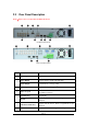
2.3 Rear Panel Description Notice:Please refer to real product for different model. DVR-470 Rear Panel DVR-1670 Rear Panel Index 1 Physical Interface Description Video Input Standard BNC. Video Output Connect monitor, output video and menu. Audio Output 1 channel RCA (1.0 Vp-p, 75Ω) 3 Audio input 4 channel RCA (1.0 Vp-p, 75Ω) 4 Video Loop out DVR-1670 uses DB15 connectores. DVR-470 uses on board BNC connectors. VGA Interface VGA display. RS-232 Connect RS-232 devices.
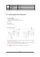
8 2.4 External Alarm Input 4/8/16 Alarm in. Relay Output 2/4 Alarm out AC Input 100V~240VAC External Alarm In/Out Connection Alarm input port: G (GND):Conenct the GND of sensor. 1~16:Alarm input, support normal open/normal close. 0:Reserved. Alarm output: 1G~4G:4 relay output. Alarm output connection Please note the usage of jumper JJ1. If you use DC, either of connections is OK. We suggest you to use those DC under 12V, 1A. If you use AC, please open the jumper.
Chapter3 Operational Instructions 3.1 Front Panel n o p Index Type Name READY STATUS ALARM RECORD NETWORK q r Description DVR is ready. Green means you can use IR remote control. Red means there is alarm. Twinkle in red means reading or writing HDD. Network status. 1 State Lamps 2 Lamp IR receiver. Numeric Keys Input number, lower case, upper case character and symbols. MENU 1. 2. 3. Switch preview mode into menu; Brush control short key【WIPER】.
4 5 REC 1. Manual record; 2. 【SHOT】in PTZ control (adjust preset). PTZ 1. Enter into PTZ control mode; 2. 【IRIS-】in PTZ control.. PREV 1. 2. A 【FOCUS-】in PTZ control. 1. Input switch (number, lower case, upper case and symbol); 2. 【FOCUS+】in PTZ control; 3. In preview mode, display or hide the channel status bar. SHIFT Switch between numeric keys and function keys Direction Keys Composed of 【Ç】,【È】,【Å】 and 【Æ】. 1. Menu mode, use【Å】/【Æ】 select,【Ç】/【È】 to edit; 2. PTZ direction control; 3.
3.2 IR Controller Index Name Description 1 POWER Turnoff device. 2 DEV Enable/Disable IR remote control 3 Numeric Keys Same as numeric keys of front panel. 4 EDIT Same as EDIT key of front panel. 5 A Same as A key of front panel. 6 REC Same as REC key of front panel. 7 PLAY Same as PLAY key of front panel. 8 INFO Same as INFO key of front panel. 9 VOIP Same as VOIP key of frint panel. 10 MENU Same as MENU key of front panel. 11 PREV Same as PREV key of front panel.
15 Reserved 16 F1 Same as【F1】key of front panel. 17 Lens control IRIS, FOCUS control. 18 F2 Same as【F2】key of front panel. ZOOM for lens Loading the batteries into the IR controller 1. Remove the battery cover. 2. Insert the battery. Please take care that the poles (+ and -) are correctly positioned. 3. Replace the battery cover. Start to use IR controller Press【DEV】key, input the DVR device ID (default is “88”, can be changed in “Display” menu) and then press【ENTER】key.
3.3 Menu Description 3.3.
Transaction Text input mode ATM IP address ATM type Text information Utilities Restore parameters Upgrade firmware HDD management Clear alarm output Reboot Power off View log System information 3.3.2 Menu Operation How to enter into menu mode z Press【MENU】key to enter into DVR main menu. z Press【PLAY】short key to enter into playback menu. z Perss【REC】short key to enter into manual record menu. z Perss【PTZ】short key to enter into PTZ control interface. Notes:You must input user name and password.
Each menu contains different kinds of items. There is a small rectangular frame named “Active Frame” which is pointing to the selected item. This “Active Frame” can be moved by 【Æ】or【Å】keys. There are such kinds of menu items: 1. Check Box:Provide 2 options, “9” means enable and “×” means disable. You can use 【ENTER】or【EDIT】key to switch over. 2. List Box:Provide more than 2 options. However, only one of them can be selected. You can use【↑】and【↓】to select one option.
3.4 Character Input In the menu interface, if you enter into edit status (for example, in the “camera name” edit box), at the bottom of screen, the input status is appeared: Here it means you can press numeric keys to input digital number. Press【A】key to change input methods. You can select “number”, “Uppercase”, “Lowercase” or “Symbol”. Uppercase Lowercase Symbol There are 24 symbols in all. They are divided into 4 pages, and you can use【0】key to turn over page.
Chapter4 Basic Operation Guide 4.1 Power on Note:Please make sure the power supply matches DVR and AC cable connected correctly. Before switch DVR on, please connect one monitor with VOUT or VGA interface. Otherwise, you can not see graphic user interface and can not operate. If【POWER】lamp is off, please do as following: Step1:Connect AC cable correctly; Step2:Switch on the power button on the real panel. If【POWER】lamp is in red, just press【POWER】button to start DVR.
Camera record status is following: Icon Icon Color Status Description White No video signal Yellow Vdieo input Pink Manual recording Green Real time recording Blue Motion detect recording Red External alarm recording Page 20
Camera alarm status is following: Icon Icon Color Status Description White Video signal lost Yellow View tampering alarm Pink Motion&External alarm Green No alarm Blue Motion alarm Red External alarm Press numeric keys to switch over individual camera preview. If DVR has less than 10 channels, press one numeric key to switch corresponding channel. For example, press【2】key to preview 2nd camera. If DVR has 10 or more than 10 channels, press two numeric keys to switch corresponding channel.
4.3 User name and password Note:When DVR is delivered from factory, there is only one default administrator named “admin”, and password is “12345”. The administrator’s name can not be modified, while the password can be modified. The administrator can create 15 users and define their user rights. Login Login dialog is following: Use【Ç】【 / È】keys to select one user, perss【Æ】key to enter into “Password” edit box, input corresponding password, press【ENTER】key to exit edit box.
Setp 2:Enter into password modification menu Move the “Active Frame” to “Password” icon by using【Æ】/【Å】keys. Press【ENTER】 key to enter into following password menu: Step 3:Input new password Press【EDIT】key to enter into edit box. You can use numeric keys to input new password. The password can be null. It also can be 16 numerals. Press【ENTER】to exit edit box, and move to “Verify” item to input the verify password.
4.4 PTZ Control Note:The user must have the “PTZ control” right. PTZ control interface In preview mode, press【PTZ】key, in the login dialog, select one user name and input the correct password, you can enter into PTZ control interface. In menu mode, press【PTZ】key, you can enter into PTZ control interface directly. There is “PTZ Control” prompt in the PTZ control interface. The displayed camera name means which channel’s PTZ is under control.
Adjust preset description In PTZ control mode, press【REC/SHOT】key, and press the preset number (three numeric keys), DVR will adjust the corresponding preset number. Repeat pressing【REC/SHOT】key, and press the preset number, DVR will adjust that preset number. When you exit PTZ control mode, the camera will stay at the current position. Note:The PTZ preset number is set already. Please refer to PTZ menu for preset setup. V1.4 firmware can support 128 preset numbers at most.
4.5 Manual Record Note:The user must have the corresponding right, DVR has HDD and HDD is formatted already. Manual record In preview mode, press【REC】key, in the pop-up login dialog, select the name and input the correct password, you can enter into the “Manual Record” interface. In menu mode, press【REC】key to enter into “Manual Record” interface directly. Description Manual record interface has following parts:channel number, channel status, start/stop record, start all and stop all buttons.
4.6 Playback Note:The user must have “Playback” right. Playback interface In preview mode, press【PLAY】key, in the pop-up login dialog, select username and input correct password, you can enter into “Playback” interface. In menu mode, press【PLAY】key, you can enter into “Playback” interface directly. Playback Description This series DVR only supports one channel playback, Chan:Use【↑】or【↓】key to select one channel. Rec Type:Use【↑】or【↓】to select recorded files type.
Play by Time:Playback the recorded stream directly based on the time section. Select Page:In the file list box, each page will only display 8 files. If the matched files are more than 8, you can select page to list other files. 500 pages (4000 files) can be searched in one time. You can use numeric keys or 【↑】【↓】keys to select page. File List Box:List the matched files. File started time, file size are displayed in the list box. You can use【↑】【↓】keys to move the scroll bar to select file.
3. Search by Card No and Playback file:In the playback interface, select channel number, record type, enable card No. search option (“9”) and input the card number, move “Active Frame” to “Search” button, press 【ENTER】key, DVR will search and list the matched files. If the matched files are more than 8, you can use numeric keys or【↑】 【↓】keys to select page. Use【↑】 【↓】keys to move scroll bar to the file, press【ENTER】key to playback the selected file.
Exit playback In playback interface, press【ESC】key to enter into preview mode. In playback interface, press【MENU】key to enter into main menu, press【REC】key to enter into manual record, and press【PTZ】key to enter into PTZ control mode.
4.7 Backup Recorded Files Note:The user must have “Playback” right. Please connect with backup devices before you start to backup. In the playback interface, you can backup the recorded files. In the preview mode, press【PLAY】key, in the login dialog, select username and input the correct password, you can enter into the playback interface. In the menu mode, just press【PLAY】key, you can enter into playback interface directly.
Step 2:Select the files that you want to backup In the file list box, use【↑】or【↓】keys to move the scroll bar. When the scroll bar stays at the file you wan to backup, press【EDIT】key to select it. The symbol “9” is the selection tag. You can use the same method to select other files you want to backup. After finish, you can do next step. Step 3:Select backup device Please confirm the backup device:USB flash memory, USB HDD, USB CD-R/W or IDE CD-R/W, and select the corresponding backup device.
4.8 Shut Down DVR Note:Do not switch off the power directly in case of damaging HDD. The correct step is using “Power Off” in the “Utilities” menu, or【POWER】key on the front panel or on IR controller. Shut down DVR normally Use menu Enter into “Utilities” menu, move “Active Frame” to “Power Off” button and enter into power off dialog, press “Confirm” to shut down the DVR. Use【POWER】key of front panel or IR controller Press【POWER】key for above 3 seconds.
Chapter5 Parameters Setup Guide Only the users that have “Parameters Setup” right need read this chapter. When the following parameters are modified and saved, you must reboot the DVR to make the new parameters take into effective. Other parameters do not need to reboot.
Move “Active Frame” to “User” icon, press【ENTER】key to enter into “User Management” menu. In the user name list box, only “admin” is existed. You can use【→】key, move “Active Frame” to password edit box, and press【EDIT】key to enter into edit status. Press numeric keys to input the new password. The password is only combined by 16 numerals at most. After you finish inputting password, press【ENTER】key to exit. Move “Active Frame” to “Verify password” edit box, input the verify password.
5.2 Add and Delete User Enter into “User Management” interface. Add user The steps are following: Step 1:Enter into “User Management” menu Please refer to chapter 5.1 Step 2:Add new user name In the “User Management” menu, move “Active Frame” to “Add” button and press 【ENTER】, in the pop-up dialog, input the new user name (refer to chapter 3.4), press 【ENTER】and return “User Management” menu. 15 users can be added in all.
In the users list box of “User Management” menu, use【Ç】 【È】keys to select the new user name, then use【Æ】key to “Default Rights” button, press【ENTER】, the user will have the default rights. The default rights include local playback, remote playback and view log. If you want to define the detail rights, move “Active Frame” to “Setup Rights” button and press【ENTER】to enter into rights setup menu as following: Operational rights are divided into “Local Rights” and “Remote Rights”.
“Remote Rights”: PTZ Control:Remote control PTZ; Record:Remote manual start/stop recording; Playback:Remote playback, download the recorded files on DVR; Parameters Setup:Remote setup the DVR parameters; Log:Remote view the log on DVR; Utilities:Remote upgrade firmware, format HDD, reboot DVR and shut down DVR, etc.
5.3 Unit Name and Device ID Unit name In the “Display” menu: There is an item named “Unit Name”. The default unit name is “Embedded Net DVR”. Move “Active Frame” to unit name edit box, press【EDIT】key to enter into edit status, you can modify the unit name. About how to input characters, please refer to chapter 3.4. Press 【ENTER】key to finish modification. Select “Confirm” button and press【ENTER】, you can save the new unit name and make it into effect.
5.4 Video Output Standard and VGA Setup Video output standard There is one VOUT BNC connector at the rear panel of DVR. It is used to connect with analog monitor and can support PAL or NTSC video output. You can modify video output standard to match video input. In “Display” menu: There is a list box named “Video Output Standard”, you can use【Ç】 【È】key to select PAL or NTSC video output. VGA setup There is one VGA interface at the real panel of DVR. You can use it to connect with VGA display.
5.5 OSD Setup OSD is abbreviation of “On Screen Display”. For our embedded DVRDVS, it includes displaying system time and camera name. OSD settings include:System time, time format, time display position, camera name, camera name display position, etc. System Time In “Display” menu, you can setup DVR system date and time. Display System Time You can setup display properties for each camera, including display status, position and format. Of course, you can copy the properties of one camera to all cameras.
Display mode:There are several display modes:Opaque&Steady, Transparent&Steady, Transparent&Flashing, Opaque&Flashing, Move “Active Frame” to “OSD” item, you can select one mode. Display position and format:Move “Active Frame” to “Position” button on the right side of “OSD”, press 【ENTER】to enter into setup image, you can find there are 22*18 (for NTSC, 22*15) small panes, and OSD position is in red. You can use【È】 【Ç】 【Æ】 【Å】keys to move the OSD position. Press【EDIT】key to select OSD format.
Chapter 3.4). The camera name can support 32 characters. Step 3:Press【ENTER】key to exit edit status. Move “Active Frame” to “Confirm” button, press【ENTER】to save the modification and you can see the new camera name. Press “Cancel” button or【ESC】key to abort. Setup Camera Name Position If you do not want to display camera name, just disable the check box beside camer name edit box. The disable flag is “×”. If you enable the check box, you can setup the camera name position.
5.6 Video Parameters Setup For different camera and different background, in order to get the best video image, you need to adjust video parameters such as brightenss, saturation, contrast and hue, etc. You can setup the camera individually, and also you can copy the video parameters of one camera to any other cameras. Here are the setup steps: Step 1:Enter into “Image Setup” menu: Step 2:Select camera:Please use【Ç】 【È】keys to select one camera.
5.7 Mask Area Setup In some cases, maybe you want mask the sensitive area. This area will not be preview and recorded. The mask area setup steps are following: Step 1:Enter into “Image Setup” menu: Step 2:Select one camera:You can use【Ç】【È】keys to select one camera. Step 3:Enter into mask area setup interface:Enable the check box beside “Privacy Mask” item, you can press【EDIT】key to change the flag into “9”, and active “Area” button.
(22*15 for NTSC), you can use【↑】 【↓】 【→】 【←】keys to move the yellow pane to your hope position and press【EDIT】key, the yellow pane will be turned into red, then you can use【↑】 【↓】 【→】 【←】keys to extend the red pane. This red area is the mask area. After you make sure the red mask area, press【EDIT】key to save the mask area. Press【ESC】 key to cancel the mask area. The maximum mask area size is 8*8 panes and the minimum size is only one pane. You can setup 4 mask areas at most.
5.8 View Tampering Alarm If you enable this function, when someone blocks the camera spitefully, DVR will make warning alarm. Step 1:Enter into “Image Setup” memu: Step 2:Select camera:Please use【Ç】 【È】keys to select one camera. Step 3:Select sensitivity:You can use【↑】【↓】keys to select the sensitivity for “View Tampering” item. The sensitivity options are: Low, Normal and High. Select one of them will active “Area Setup” and “Policy Setup” function.
Step 6:Alarm schedule setup:When there is view tampering alarm happened, DVR will handle the alarm based on the schedule. You can set 4 periods for each day one week. Also you can copy the schedule of one day to other days. Notes:Time periods can not be repeated. Please reboot DVR to make the parameters into effective. Step 7:Setup alarm policy:If there is view tampering alarm happended in schedule, DVR will response based on the policy.
5.9 Video Loss Alarm When the video cable or camera has something wrong, the video image is lost. If you enable video loss alarm, in such case, DVR will make alarm. Step 1:Enter into “Image Setup” menu: Step 2:Select camera:Use【Ç】【È】keys to select one camera. Step 3:Enter into “Video Signal Loss Handle” interface:Move “Active Frame” to the list box on the right side of “Video Loss” item, use【Ç】key to select “Handle” option and move “Active Frame” to the “Policy” button on right side.
Step 5:Setup alarm policy:You can select one or more response solutions, including “On Screen Warning”, “Audible Warning”, “Upload to Center” and “Trigger Alarm Output”. You can use 【↑】 【↓】and 【EDIT】key to enable or disable them. “×” is disable and “9” is enable. Step 6:Save alarm setup:After your setup, press “Confirm” button and return “Image Setup” interface. In “Image Setup” menu, press “Confirm” button to save current camera parameters and return main menu.
5.10 Motion Detection Alarm If you enable this function, when there is motion detected, DVR will make alarm. Step 1:Enter into “Image Setup” menu: Step 2:Select camera:Use【Ç】【È】key to select one camera. Step 3:Select motion detection sensitivity:On the right side of “Motion Det. Level” item, there is a list box. That is motion detection sensitivity. There are 7 options, from 0 (the lowest) to 5 (the highest) and “Off”. You can use【↑】【↓】keys to select one.
The whole screen is divided into 22*18 panes (NTSC:22*15). There is one yellow panel on the upper left side. The motion area setup steps are the same as that of mask area setup (refer to chapter 5.7). The only differences are that you can use【PTZ】key to set the whole screen as motion area, and mutil motion areas can be defined. Press【A】key to clear all motion areas. Setup multi areas:After you setup one motion area, press【EDIT】key, the yellow pane will appear again, then you can setup another motion area.
Step 6:Motion alarm record channel setup:When there is motion alarm happened, you can trigger related camera to start recording. In “Motion Alarm Handle” menu, you can select one or more record channels. Please use【ENTER】or【EDIT】key to enable the flag into “9”. Note:In order to make the cameras start recording, in “Recording” menu, you must enable recording schedule and set “Rec Type” as “Motion Detection” or “Motion | Alarm”. Please refer to chapter 5.12 for recording setup.
5.11 Preview Properties In “Preview” menu, you can setup preview mode, screen switch time, enable or disable audio preview and preview layout. Step 1:Enter into “Preview” menu:In the main menu, move “Active Frame” to “Preview” icon and press【ENTER】, you can enter into “preview” menu. Step 2:Preview properties: Preview mode:For preview mode item, you can use【↑】【↓】key to select one mode. If DVR has only 1 channel, you can select only “1 Screen” option.
Preview layout setup:There is a square frame divided into many windows. If you select “4 Screen”preview mode, this frame is divided into 4 windows. Each window represents one camera. You can move “Active Frame” among the windows. There is one bar under the square to display the preview order of all cameras. First select the biggest screen preview mode, for example, for 16-channel DVR, select “16 Screen” preview mode so that all windows are display in the square.
5.12 Recording Setup In main menu, there is an icon named “Recording”. You can enter into recording menu as following: “Recording” menu description: If HD Full:There are two options:“Overwrite” and “Stop recording”. If you select “Overwrite” option, when all HDDs in DVR are full, DVR will overwrite the earliest recorded files and continue recording. If you select “Stop recording” option, when all HDDs are all full, DVR will handle it as “Hard Disk Full” exception, please refer to chapter 5.
If you select variable bit rate, DVR will adjust the actual bit rate according to the video movement. When there is not much movement, DVR will use low bit rate, while there is much movement, DVR will use high bit rate. In this case, DVR can save HDD usage and network bandwidth. If you select fixed bit rate, DVR will use the fixed bit rate to compress iamge. The bit rate size is defined in “Max Bit Rate” option. In this case, we can calculate the recorded file size and network bandwidth that we need.
Note:When the camera’s recording schedule is modified, you must reboot DVR to make it into effective. All day recording setup: Step 1:Enter into recording schedule menu In recording menu, use【ENTER】or【EDIT】key to enable record function (“9” flag), press “Schedule” button to enter into recording schedule menu. Step 2:Select ond day and enable all day recording option For “Day” item, there are options:Monday, Tuesday, Wednesday, Thursday, Friday, Saturday and Sunday. Use【↑】 【↓】keys to select one day.
Step 1:Enter into recording schedule menu In recording menu, use【ENTER】or【EDIT】key to enable record function (“9” flag), press “Schedule” button to enter into recording schedule menu. Step 2:Select ond day and disable all day recording option For “Day” item, there are options:Monday, Tuesday, Wednesday, Thursday, Friday, Saturday and Sunday. Use【↑】 【↓】keys to select one day. Move “Active Frame” to the check box on the right side of “All Day” item, press【ENTER】or【EDIT】key to disable “All Day” option.
5.13 External Alarm Input and Relay Output For DVR-470, there are 4 external alarm input and 2 relay output. For DVR-1670, there are 16 external alarm input and 4 relay output. In “Alarms” menu, you can setup for each external alarm input. In main menu, move “Active Frame” to “Alarms” icon and press 【ENTER】key to enter into alarms menu: External alarm input setup: Step 1:Select one alarm input Use【↑】【↓】keys to select one alarm input. Step 2:Alarm type This is sensor type.
Step 4:Alarm trigger record channel setup You can select channels to record for each alarm input. In the sub menu, you can use 【ENTER】or【EDIT】key to enable record channel. “×” means disable and “9 means enable. Note:In order to trigger the channel to record, in “Recording” menu, you must enable recording and select record type as “Alarm” or other related type. Please refer to chapter 5.12.
First select one camera, then select one of following PTZ linkage: z Preset:Set the flag as “9” to enable preset, in the preset number edit box and input one preset number that has been setup already. Please refer to chapter 5.15 for preset setup. z Sequence:Set the flag as “9” to enable sequence and input one sequence number that has been setup already. Please refer to chapter 5.15 for sequence setup. z Cruise:Set the flag as “9” to enable cruise. Please refer to chapter 5.15 for cruise setup.
Step 3:Enter into alarm out schedule You can set the schedule to make alarm output into effective. Move “Active Frame” to “Schedule” button on right side of “Alarm Out Time” item, press【ENTER】key to enter into the corresponding schedule menu: Step 4:Setup alarm out schedule Like other schedule setup, you can set 4 time periods for one day and 7 days for one week. When you finish setup, press “Confirm” button to return “Alarms” menu.
5.14 Network Parameters If you want use network to access DVR, you must setup network parameters. Note:If any network parameter is modified, you must save and reboot DVR to make it into effective. In main menu, move “Active Frame” to “Network” icon and press【ENTER】, you can enter into “Network” menu as following: “Network” menu description: *NIC type:Defautl is “10M/100M Auto”, the other options are:10M Half-Dup, 10M Full-Dup, 100M Half-Dup and 100M Full-Dup.
This DNS is special software, not the normal domain name server. You can use the provided SDK to develop this DNS software. Multicast IP:It is one D-class IP address, among 224.0.0.0 --- 239.255.255.255. If you do not use multicast function, you do not need to set. Some routers will prohibit multicast function in case of network storm. Remote Host IP and Port:If you set this IP and port, when there is alarm and exception happened, DVR will send information to that host IP.
PTZ menu description Select channel:Select one PTZ camera. RS-485 parameters:Including baudrate, data bit, stop bit, parity, flow control, etc. These parameters must be the same as those of PTZ. Protocol. PTZ address:Each PTZ has one different address.
Cruise setup:Cruise is remembering the track of PTZ movement. Please make sure the PTZ you are using can support cruise function. Preset setup In “PTZ” menu, move “Active Frame” to “Setup” button on the right side of “Preset” item, press【ENTER】, you can enter into “Preset” setup menu: Add preset number:You can input preset number (among 1-128) in the edit box. Then press “Adjust” button to enter into PTZ control interface.
In “Sequence” setup menu, first input the sequence number. The sequence is among 1 --- 16. Each sequence is made up of cruise points, and each cruise point includes preset number, dwell time and dwell speed. Dwell time is the time staying at that preset number. Dwell speed is the speed that PTZ is moved to that preset number. Press “Add” button to add one cruise point. Press “Confirm” button to save the cruise point into the sequence.
Press “RecCru” button, you will enter into “PTZ control” interface. You can start controlling PTZ with direction keys, press【ENTER】to save the operation track and return “Cruise” setup menu. Press “StartCru” button to repeat the PTZ track until you press “Stop” button. Press “Return” button back to “PTZ” menu. In “PTZ” menu, press “Confirm” button to save this cruise. Please make sure the PTZ you are using can support cruise function.
5.16 RS232 setup There is one RS-232 port at DVR rear panel. In main menu, move “Active Frame” to “RS232” icon and perss【ENTER】key, you enter into “RS232” setup menu: RS232 menu description RS-232 parameters:Including baud rate, data bit, stop bit, parity, flow control, etc. Work mode:The RS-232 can be used as “Console”, “PPP” or “Transparent Channel”. Console:Connect with PC serial port. You can use HyperTerminal or NetTerm to control it. PPP:Connect Modem, using PSTN to transfer video image.
Username, password and Verify password:Only used when work mode is “PPP”. Used for login when remote PC dialup through PSTN. Phone:Only used when work mode is “PPP” and PPP mode is “Active”. It is the phone number of remote PC. Callback and Data Encryption:Only used when work mode is “PPP”. They are not available. Confirm:Save parameters and return main menu. Cancel:Abort modification and return main menu. Example:PPP (Modem) passive dialup through PSTN There are two Modems.
Step 3:Save setup In “Recording” menu, press “Confirm” button to save parameters. Step 4:Setup Modem used on DVR side Use DCE calbe to connect Modem with PC serial port. You can use HyperTerminal or NetTerm to setup modem: AT&F ---- Retore default parameters (Generally, Modem is hard flow control) AT&S0=1---- Set Modem as answer ATE0 ---- Not display the input characters ATQ1 ---- Commit instruction and not display AT&W&W1 ---- Save parameters Step 5:Use DCE cable to connect Modem with DVR RS232 port.
Page 73
Step 3:Establish the dialup connection Select the Modem connected with PC just like the dialup network connection, input the telephone number connected with DVR’s modem. Input the username, password. They must be the same as that DVR PPP setup. Step 4:During the dialup connection, it will give the message of “verification of username and password”, after successfully verification; the message will be given “on process of register in PC”. The process is the same as the common dialup connection.
5.17 Exceptions The exceptions can be handled at present include: hard disk full, hard disk error, illegal access, IP address conflict, network failure, and NTSC/PAL differ. Enter into “Exceptions” menu: Including the following handle methods: Audible Warning:DVR beep warning. Upload to Center:Send exception information to center host PC. Trigger Alarm Output:trigger local relay output. You can select more than one handle methods. After you finish setup, press “Confirm” button to save parameters.
5.18 Transaction Information The DVR can actively obtain or passively receive the credit card number from ATM machine linked through network or serial port, and credit card number can be overlay on live video, recorded and playback. The following description indicates how to carry out relevant parameter setting according to different links to ATM machine. In “Transaction Information” menu, there are 4 kinds of text capture solutions: 1.
Start & end position and length of transaction type Transaction type and code When the ATM machine is sending transaction information to bank center, DVR will capture the data package through network, and analyse the data according to the format. Then DVR will overlay the correspond text on live video. 2. Network receive:DVR receives data sent by ATM machine through network. You only need to setup DVR listen port. The default port value is 10000.
In the case, you must set the RS-232 of DVR as transparent channel mode as following: A software must be run in the ATM machine, and send the credit card number, transaction code to DVR through RS-232 port. Please provide detail ATM machine communication protocol for actual projects. 4.
In the case, you must set the RS-232 of DVR as transparent channel mode as following: Also, a software must be run in ATM machine, and send command to DVR through RS-232 port based on special communication protocol.
Chapter6 Utilities There are many tools in “Utilities” menu. Including “SavePara”, “RestorePara”, “Upgrade”, “Hard Disk”, “Stop Alarm Out”, “Reboot”, “Power Off”, “View Log” and “System Info”. Enter into “Utilities” menu: 6.1 Save Parameters Save factory default parameters into FLASH memory. You can reboot DVR to make them into effective. 6.2 Restore Parameters Restore factory parameters for DVR. The IP address, gateway and port number will not be restored.
6.3 Upgrade You can use this function to upgrade the firmware. Please confirm the language is matched. Press “Upgrade” icon, in the pop-up dialog, you can select either “FTP” or “USB” upgrade mode. If you select “FTP” mode, you will enter into “FTP Upgrade” menu: Input the ftp server IP and press【ENTER】key. DVR will connect with FTP server through network and download the firmware file.
6.4 Hard Disk Management Check HDD work status Capacity, Free space, Stand by or not, Normal status or not. Format HDD Before formatting stop all recording. After formatting, you must reboot DVR, otherwise DVR will not work normally. 6.5 Clear Alarm Out Clear the alarm output manually. 6.6 Reboot Reboot DVR. 6.7 Power Off Shut down DVR. 6.8 View Log To view the log recorded in DVR HDD.
If you want to view the log based on default option, just press【ENTER】key. DVR will list all matched information. Also you can select options to search (By Type, By Date, By Type&Date). By Type To view log information of the assigned type. Type is divided into “Major type” and “Minor type”. Major type includes operation, alarm, exception and all.
Step 4:When searching is finished, DVR will list all matched alarm information. In the list box, the information includes:Index, Occur Time, Major Type, Minor Type, Panel User, Net User, Host Address, Para. Type, Channel No, HDD No, Alarm In and Alarm Out. You can press “More Info” button for more information, also slect page number to view more information. Step 5:Press “Return” button back to “Utilities” menu. By Time View the log between one time period.
6.
Chapter7 Firmware Upgrade The DVR firmware is stored in FLASH ROM. You can use DVR upgrade function to write the firmware file (digicap) into FLASH. There are two cases that you need to upgrade DVR firmware. One is update old firmware. The other is when the code in DVR FLASH is crashed. Note:Make sure that the DVR and the firmware are compatible before the upgrade. 7.1 FTP Server Setup You can download FTP server software through internet. Here we use wftpd32.exe as the example: 1. Run wftpd32.
3. Select “Users/rights” under “Security” menu item. The following dialog box will be pop-up. 4. Create new user. Click “new user’. New user dialog pops up. Input user name “target”. Click “OK”. 5. In the password dialog, input password “target” in “New Password” and Password” edit box. Click “OK” to save and exit the dialog box.
6. In the “User/Rights Security” Dialog, select “User Name” as “target”. In “Home Directory” edit box, input the path where the firmware file (digicap) is placed. Then press “Done” to exit. 7. Next time, you need not setup again, just double click and open “wftpd32.exe” to upgrade the DVR/DVS firmware.
7.2 Upgrade Mode 1. Use client software to upgrade the firmware file. You do not need to use ftp server software. Please refer to the client software user manual for detail information. 2. Use “FTP” function of “Upgrade” sub menu in “Utilities” menu. You need one host PC to run FTP server software and place firmware file (digicap), and make sure DVR and PC are in the same sub net. 3. Use “USB” function of “Upgrade” sub menu in “Utilities” menu.
Appendix A DVR Connect Cable Definition 1 UTP network connect cable made method Material and tool One twist cable (8 pin, the length can be defined as to the actual demand, but must be within 100m), 2 standard RJ45 head, one tool for RJ45. Suggestion:have a network cable test tool to test each cable made. Pin definition To make the network cable according to the actual situation, there are two options: (1) Use the following method to make the network cable when DVR is connected with network hub or switch.
The corresponding relationship of cross cable 2 RS-232 connect cable made method DVR-802x has standard DB9 RS-232 interface, like PC COM port. Pin definition “I” means DVR input and O means DVR output.
Appendix B Specifications Model name DVR-1670 DVR-470 Video compression H.264 Preview resolution PAL:704*576 (4CIF), NTSC:704*480 (4CIF) Playback resolution CIF/QCIF Video input 4 16 Video input interface BNC (Electrical Level:1.0Vp-p, resistance:75Ω) Video output 1 channel, BNC (Electrical Level:1.
Power supply 100~240VAC, 6.3A, 50~60 HZ Power consumption 20--42W (without HDD) Working temperature -10℃--+55℃ Working humidity Size Weight 10%--90% 14.25 inch standard (440mm*390mm*70mm) ≤8Kg (without HDD and CD-R/W) PAL:176*144(QCIF), 352*288(CIF), 704*288(2CIF), 528*384(DCIF), 704*576(4CIF); NTSC:176*120(QCIF), 352*240(CIF), 704*240(2CIF), 528*320(DCIF), 704*480(4CIF).
Appendix C List of Recommended DVR Peripherals USB DVD-R/W: 1. LG GSA-E10L 2. BENQ EW164B USB CD-R/W: 1. BENQ external 5232WI-ok2 2. ASUS CRW-4824A + USB Convertor case 3. SONY CD-R/RW CRX230AD + Convertor cable 4. SONY CD-R/RW CRX225E + Convertor cable 5. BENQ external EW162I-OK2 IDE CD-R/W: 1. Sony CD-R/RW CRX225E 2. NEC DVD R/RW & CD-R/RW ND-3500A 3. Toshiba Samsung CD-RW SH-R522 4. LG GCE-8525B CD-R/W IDE HDD: Maxtor: 1. DiamondMax Plus 9 80G ATA/133 HDD 2. DiamondMax Plus 9 160G ATA/133 HDD 3.
West Digital: 1. WD Caviar WD400BB 2. WD Caviar WD800BB 3. WD Caviar WD1200BB 4. WD Caviar WD2000BB 5. WD Caviar WD2500BB 6. WD Caviar SE WD1600BB 7. WD Caviar SE WD2000JB 8. WD Caviar SE WD2500JB 9.
Appendix D Quick Search Function Table Type Safety function HDD recording Name Description Index User management Create and delete users. System has one default administrator. The administrator can create 15 users and define their rights. 5.2 Password Management Modify password. HDD management Format HDD, HDD information. 6.4 Recording mode Manual record, All time record, Motion detection record, Alarm record, Motion&Alarm record, Motion|Alarm record. 5.12 Recording para.
Remote record Remote record real time stream. * Remote playback Remote playback the recorded files in DVR * Download Download recorded files in DVR. * Remote upgrade firmware. * Remote upgrade Transparent channel Web Utilities Remote control serial device connected with serial port of DVR. Using IE to access DVR 5.16 * PSTN Access DVR through PSTN. 5.16 OSD OSD setup 5.5 LOGO Logo setup 5.5 View log 6.
Appendix E Troubleshooting Failure Possible reasons After plugging in power, turning on the power switch, “POWER” light in front Panel does not turn on, and fan does not work. 1) 2) Power cable is broken. Power supply is broken. After plugging in power, turning on the power switch, “POWER” light in front panel turn to green while fan does not work. 1) 2) Front panel cable is broken. Fan is broken.
3) Old player SDK (playm4.dll) Notes: 1) Place the DVR in well ventilated space so that it operates within the allowed range of temperature and humidity as in specification. 2) If the circuit board is wet, dust on circuit board can cause a short circuit. The circuit board, lug and socket, housing fan and housing should be cleaned by brushing regularly.