Serial WAN Router ERT-805 User’s Manual
Trademarks Copyright PLANET Technology Corp. 2004. Contents subject to revision without prior notice. PLANET is a registered trademark of PLANET Technology Corp. to their respective owners. All other trademarks belong Disclaimer PLANET Technology does not warrant that the hardware will work properly in all environments and applications, and makes no warranty and representation, either implied or expressed, with respect to the quality, performance, merchantability, or fitness for a particular purpose.
TABLE OF CONTENTS Chapter 1 Introduction ............................................................................................................ 1 1.1 CHECKLIST ......................................................................................................................... 1 1.2 ABOUT ERT-805................................................................................................................ 1 1.3 PRODUCT FEATURE .....................................................................
.7 X.25 PROTOCOL .............................................................................................................. 33 4.8 FRAME RELAY PROTOCOL................................................................................................. 37 Chapter 5 Security ................................................................................................................. 41 5.1 ACCESS-LIST .......................................................................................................
Chapter 1 Introduction 1.1 Checklist Thank you for purchasing Planet’s ERT-805 Enterprise Serial Router. Before continuing, please check the contents of your package for following parts: Ø ERT-805 Serial WAN Router Ø Power Cord Ø DB9 adapter Ø RJ-45 to RJ-45 modem cable Ø User’s Manual CD Ø Quick installation Guide if any of these pieces are missing or damage please contact your dialer immediately. 1.
Ø ERT-805 supports SNMP and can be managed by using SNMP management software 1.3 Product Feature Ø Support PPP, FR, X.25, HDLC, LAPB, SDLC, SLIP and Stun Ø Complies with IEEE802.3 10Base-T, IEEE 802.
Power Input 100 ~ 240V AC (+/-10%); 50/60Hz (+/-3%) auto-sensing Power Consumption 10 watts / 34BTU Dimensions 217 x 135 x 43 mm (1U height) Weight 1 Kg Temperature 0 to 50 degree C (operating) -20 to 70 degree C (storage) Humidity 10 ~ 90% RH (non-condensing) Regulatory FCC, CE class A 3
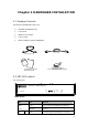
Chapter 2 HARDWARE INSTALLATION 2.1 Package Contents Item includes with ERT-805 serial router. Ø ERT-805 Serial WAN Router Ø Power Cord Ø DB9 to RJ-45 changer Ø Console cable Ø Quick Installation Guide and CD-ROM Console Cablecable Light blue console Black power cord DB-9-to-RJ-45 adapter (for use with blue Cable) console cable) (forlight Console CD-ROM user’s Guide & Quick Install Guide 2.2 ERT-805 outlook 2.2.
LNK/ Green blink This indicator light blink when packets is transmit ACT Green This indicator light green when port is connected This indicator light green when port is connect with Green serial port Serial Blink This indicator light blink when packets is transmit Green blink Configuration process Lights Off Not in configuration Console Rear Panel 100~240V AC Console Serial Sync. Async.
2.
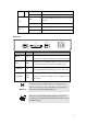
Available connection is as tables below: WAN Option RS-232 X.21 V.24 V.35 WAN Encapsulation Link control (HDLC) or ppp Frame-relay X.25 2.3.4 Power on the device ERT-805 accepts power input from 100 to 240VAC, 50/60Hz power source. Before connect the power cable to the router, please be sure the AC power output from your power outlet. The router must connected to earth ground during normal use. ERT-805 is a power-required device, it means, ERT-805 will not work until it is powered.
Chapter 3 Command Line Interface This chapter describes the basic commands to access the router through console interface or telnet. Be noted if you want to login to ERT-805 through the telnet, then enable password must be configure. The user can input system command configuring system protocol by command line port. When you first login a new router by terminal, the system will give a prompt router>. Now you are in user mode.
ERT_805> ? disable enable exit help logout pad ping ppp schedule show telnet traceroute tty ERT_805> Turn off privileged commands, enter GUEST user mode Turn on privileged commands Exit from the EXEC Description of the interactive help system Exit from the EXEC Open a X.
clockrate 48000 ! ERT_805(config-serial0/0)# 3.4 Ctrl-Z, Ctrl-C and exit To exit from the configuration mode directly to privilege mode, you should type Ctrl-Z or Ctrl-C or type exit. Ctrl-C can be available in other occasions .For example it can stop the current operation that hasn’t been accomplished. 3.5 Login from Console port Once the terminal has connected to the device, power on the device, the terminal will display that it is running POST (Power on self-test) procedures.
telnet. If configures like below, the system will only ask for password when anyone access. For example set the password as “1234”. ERT805> enable ERT805# config t ERT805(config)# enable password 1234 ERT805(config)#line vty 0 4 ERT805(config-line)# login ERT805(config-line)# password cisco ERT805(config-line)# exi ERT805(config)# exit ERT805# The password is set by the command “password” in vty and has no concern with what have been configured above by the command username.
Router Software Version 4.2c on Hex_1f73 (3805a) User Access Verification Username: rr Password: (type the password cisco) ERT805> 3.7 Password Encryption Security is a most important issue for all the company in the world because all the system is require password to protect important information from hacker, such as username, enable password…etc. In default the system will display these password by clear. So the password is not very secure.
crypto isakmp key 12345678 address 10.0.0.2 255.255.255.192 ! interface fastethernet 0/0 ip address 192.168.99.64 255.255.255.0 ! interface serial 0/0 encapsulation ppp ip address 10.0.0.1 255.255.255.192 crypto map dynmap clockrate 48000 ! interface async 0/0 ! line vty 0 5 login password 7 wAVcXxom8sGSOA ! ip route 0.0.0.0 0.0.0.0 10.0.0.2 ! access-list 100 permit ip 192.168.99.0 0.0.0.255 192.168.98.0 0.0.0.
Chapter 4 Router Communication Protocol 4.1 RIP- Router Information Protocol The routing information Protocol (RIP) is a distance-vector protocol that used to exchange routing information between routers. RIP uses broadcast User Datagram Protocol (UDP) data packets to exchange routing information and rip is based on distance-vector algorithm. This routing protocol is determines the best path through an Internet by looking at the number of hops between the two end nodes.
convergence. Whenever a router changes the metric of a route, it is required to send update messages almost immediately 4.1.1.5 RIP Command router rip – enable rip in global configuration mode version - To specify a RIP version used globally by the router (version 1 and 2) auto-summary – enable automatic network number summarization.
Building configuration ... description fault service password-encryption service timestamps debug ! hostname ERT_805 ! enable password 7 3EDRIxtqRWCA ! username router password 7 65WeJR6evnrR3mP crypto ipsec transform-set transform-1 esp-3des esp-md5-hmac ! crypto map dynmap 1 ipsec-isakmp set transform-set transform-1 set peer 10.0.0.2 match address 100 ! crypto isakmp policy 1 authentication pre-share group 1 hash md5 ! crypto isakmp key 12345678 address 10.0.0.2 255.255.255.
network 10.0.0.0 network 192.168.99.0 ! line vty 0 5 login password 7 wAVcXxom8sGSOA ! ip route 0.0.0.0 0.0.0.0 10.0.0.2 ! access-list 100 permit ip 192.168.99.0 0.0.0.255 192.168.98.0 0.0.0.255 ! end ERT_805# ERT_805# show ip route Codes: A--all O--ospf S--static R--rip C--connected E--egp T--tunnel o--cdp D--EIGRP [Distance/Metric] g S 0.0.0.0/0 [2/0] via 10.0.0.2 serial0/0* act C 10.0.0.0/26 [0/1] via 10.0.0.1 serial0/0* act C 10.0.0.2/32 [1/0] via 10.0.0.1 serial0/0* act R 192.168.98.
Bind-interface – enable EIGRP protocol on some interface Distance – define an administrative distance Distribute-list – filter networks in routing updates Metric/e – modify EIREP routing metrics and parameters Passive-interface - To disable sending routing updates on an interface. Redistribute eigrp – redistribute information from other routing protocol and there are some optional value allow user to configure which is bandwidth, delay, reliability, loading and mtu.
authentication pre-share group 1 hash md5 ! crypto isakmp key 12345678 address 10.0.0.2 255.255.255.192 ! interface fastethernet 0/0 ip address 192.168.99.64 255.255.255.0 ! interface serial 0/0 encapsulation ppp ip address 10.0.0.1 255.255.255.192 crypto map dynmap ip hold-time eigrp 1 20 clockrate 48000 ! interface async 0/0 ! router eigrp 1 network 192.168.99.0 network 10.0.0.0 ! line vty 0 5 login password 7 wAVcXxom8sGSOA ! ip route 0.0.0.0 0.0.0.0 10.0.0.2 ! access-list 100 permit ip 192.168.99.0 0.0.
information between non-backbone areas Stub area – this area do not accept router that belong to external autonomous system (AS). The routers in stub area use a default route to reach outside autonomous system. Totally stubby area – This area that does not accept routes from other intra-area and default routes to be propagated within the area. If the router needs to send a packet to outside of area, it sends it using a default route.
area area-id authentification -specifying the authentification type is single authentification area area-id authentification message-digest -specifying the authentification type is Cryptographic authentication*/ area area-id stub [no-summary] - specifying the area is stub area*/ /* no-summary emphasizes the only default summary LSA produced into the area area area-id default-cost cost- For stub area, default summary LSA cost’s value area area-id nssa -specifying the area is NSSA area area area-id range addr
Password: ERT_805# show run Building configuration ... service password-encryption service timestamps debug ! hostname router ! enable password level 15 7 aNTUS0QSfz8T ! interface fastethernet 0/0 ip address 192.168.99.64 255.255.255.0 ! interface serial 0/0 encapsulation hdlc ip address 10.0.0.1 255.255.255.192 ip ospf priority 255 clockrate 48000 ! interface async 0/0 ! router ospf 2 network 192.168.99.0 0.0.0.255 area 0 network 10.0.0.0 0.0.0.
Ø PPP has a method for encapsulating multi-protocol datagrams Ø Link Control Protocol (LCP) establishes, configures, authenticates and testing the data-link connection. Ø Network Control Protocol (NCP) establish and configure different network-layer protocol. PPP provides two authentications which is: Ø Password Authentication protocol (PAP) Ø Challenge Handshake Authentication protocol (CHAP) PPP authentication using PAP PAP is using two-way handshake to establish its identity.
Figure 4-2 Networking diagram of PAP and CHAP authentication example ROUTER A ROUTER B encapsulation ppp – encapsulation style to ppp style (interface command) ppp authentication [pap | chap - enable the PAP or CHAP authentication username username password password [callback-dialstring]– add the username and password of the peer into the local user.
hostname router ! enable password level 15 7 aNTUS0QSfz8T ! username ERT-805 password 7 SBFV4NgG60tV ! interface fastethernet 0/0 ip address 192.168.99.64 255.255.255.0 ! interface serial 0/0 encapsulation ppp ip address 10.0.0.1 255.255.255.192 ppp authentication chap clockrate 48000 ! interface async 0/0 ! line vty 0 4 login password 7 hd3cpRj4s14LeA ! ip route 192.168.98.0 255.255.255.0 10.0.0.
ip address 192.168.98.63 255.255.255.0 ! interface serial 0/0 encapsulation ppp ip address 10.0.0.2 255.255.255.192 ppp authentication chap ! interface async 0/0 ! line vty 0 4 login password 7 o2EUq2a6AFiY4D ! ip route 192.168.99.0 255.255.255.0 10.0.0.1 ! end PAP example outer# show run Building configuration ... service password-encryption service timestamps debug ! hostname router ! enable password level 15 7 aNTUS0QSfz8T ! interface fastethernet 0/0 ip address 192.168.99.64 255.255.255.
interface async 0/0 ! line vty 0 4 login password 7 hd3cpRj4s14LeA ! ip route 192.168.98.0 255.255.255.0 10.0.0.2 ! end router# ERT-805# show run Building configuration ... service password-encryption service timestamps debug ! hostname ERT-805 enable password 7 5EVbxkwzBvfT ! username router password 7 qBjbURagjK0L ! interface fastethernet 0/0 ip address 192.168.98.63 255.255.255.0 ! interface serial 0/0 encapsulation ppp ip address 10.0.0.2 255.255.255.
! ip route 192.168.99.0 255.255.255.0 10.0.0.1 ! end ERT-805# 4.5 HDLC Protocol Only when the interface operates in the synchronous mode, can it be encapsulated with HDLC. encapsulation hdlc – encapsulation with hdlc type router# show run Building configuration ... service password-encryption service timestamps debug ! hostname router ! enable password level 15 7 aNTUS0QSfz8T ! username ERT-805 password 7 3hlZiJYY6pOn ! interface fastethernet 0/0 ip address 192.168.99.64 255.255.255.
end router# router# debug hdlc s0/0 router# 03:59.544 %serial0/0 Hdlc Port debug turn on 04:01.399 serial0/0 HDLC O(len=162):CDP 01 b4 cc 27 00 01 00 0a 72 6f 75 74 65 04:01.399 72 00 02 00 11 00 00 00 01 01 01 cc 00 04 0a 00 00... 04:03.094 serial0/0 HDLC I(len=22):lmi peer_seq=155,local's=159 04:03.753 %HDLC serial0/0 Keepalive 04:03.753 serial0/0 HDLC O(len=22):lmi local_seq=160,peer's=155 04:13.093 serial0/0 HDLC I(len=22):lmi peer_seq=156,local's=160 04:13.753 %HDLC serial0/0 Keepalive 04:13.
router# no 05:13.094 serial0/0 HDLC I(len=22):lmi peer_seq=162,local's=166de 05:13.753 %HDLC serial0/0 Keepalive 05:13.753 serial0/0 HDLC O(len=22):lmi local_seq=167,peer's=162 4.6 SNA 4.6.1 Introduction Switch-to-Switch Protocol (SSP) is a protocol specified in the DLSw standard that routers use to establish DLSw connections, locate resources, forward data, and handle flow control and error recovery.
sdlc role – establish role of the interface sdlc-largest-frame- Set the largest I-frame size that can be sent or received by the designated SDLC station sdlc simultaneous [full-datemode | half-datamode] - full-datemode is enable the primary station to send data to and receive data from the polled secondary station. half-datamode is Prohibit the primary stations from sending data to the polled secondary station.
hostname RouterA ! source-bridge ring-group 2000 dlsw local-peer peer-id 150.150.10.2 dlsw remote-peer 0 TCP 150.150.10.1 ! interface serial 8 IP address 150.150.10.2 255.255.255.192 clockrate 56000 ! interface tokening 0 no Ip address ring-speed 16 source-bridge 500 1 2000 source-bridge spanning Configuration for Router B hostname RouterB ! dlsw local-peer peer-id 150.150.10.1 dlsw remote-peer 0 TCP 150.150.10.2 ! interface serial 1 encapsulation hdlc Ip address 150.150.10.1 255.255.255.
4.7 X.25 Protocol The X.25 protocol is defines the connection between data terminal equipment (DTE) and circuit-terminating equipment (DCE). X.25 is the protocol of point-to-point interaction between DTE and DCE equipment. DTE usually refers to the host or terminal at the user side and DCE usually refers to the synchronous modem. DTE is connected with DCE directly.
types of VC, which is permanent virtual circuit (PVC) and switch virtual circuit (SVC). The different between PVC and SVC is PVC is permanently established connections used for frequent and consistent data transfers and not use call setup and call clear. encapsulation x25 [dce | dte] – set the encapsulation style to X.25 type x25 address – enable the X.21 address x25 map [Qllc] – Create the mapping from the destination protocol address to X.
X.25 facility facility-number window size in-size out-size Request reverse initiating a call charging while Request throughput-level negotiation while initiating a call Network user ID X.25 facility facility-number reverse X.25 facility facility-number throughput in out X.
x25 address 87654321 x25 map ip 10.1.1.2 12345678 clockrate 9600 Router2: interface serial 1 encapsulation x25 dte ip address 10.1.1.2 255.255.0.0 x25 address 12345678 x25 map ip 10.1.1.1 87654321 Access packet switching network Figure 1-16 Accessing packet switching network Router1 s1:14.1.1.1/24 x121:14111 X25 s1:14.1.1.2/24 x121:14112 Router2 s1:14.1.1.3/24 x121:14113 Router3 Router1: interface serial 1 encapsulation x25 ip address 14.1.1.1 255.255.255.0 x25 address 14111 x25 map ip 14.1.1.
x25 map ip 14.1.1.2 14112 Set up network with PVC Router1: interface serial 1 encapsulation x25 ip address 14.1.1.1 255.255.255.0 x25 address 14111 x25 ltc 3 x25 pvc 1 ip 14.1.1.2 x25 pvc 2 ip 14.1.1.3 Router2: interface serial 1 encapsulation x25 ip address 14.1.1.2 255.255.255.0 x25 address 14112 x25 ltc 3 x25 pvc 1 ip 14.1.1.1 x25 pvc 2 ip 14.1.1.3 Router3: interface serial 1 encapsulation x25 ip address 14.1.1.3 255.255.255.0 x25 address 14113 x25 ltc 3 x25 pvc 1 ip 14.1.1.1 x25 pvc 2 ip 14.1.1.2 4.
The frame relay switch, which is responds one or more LMI types. There are three different LMI types: cisco, ansi and q933a.
Figure 2-1 Configuration Example E1:142.10.2. 142.10.2.6/ Router1 24 7/24 S1:192.1.1.1 /24 16 host_a S1:192.1.1.3E1:142.10.4. /24 7/24 17 FR 16 16 S1:192.1.1.2 /24 host_b Router3 host_ c Router2 142.10.4.6/ 24 E1:142.10.3. 7/24 142.10.3.6/ 24 (1) Router1 Configuration: Router1>enable Router1#conf term Router1 (config)#interface s1 Router1 (config-if)#enca fram Router1 (config-if)#no sh Router1 (config-if)#Ip addr 192.1.1.1 255.255.255.
Router2#conf term Router2 (config)#interface s1 Router2 (config-if)#enca fram Router2 (config-if)#no sh Router2 (config-if)#Ip addr 192.1.1.2 255.255.255.0 Router2 (config-if)#fram first-dlci 16 Router2 (config-if)#fram map IP 192.1.1.1 16 Router2 (config-if)#exit Router2 (config)#int e1 Router2 (config-if)#no shut Router2 (config-if)#Ip addr 142.10.3.7 255.255.255.0 Router2 (config-if)#exit Router2 (config)#IP route 142.10.2.0 255.255.255.0 192.1.1.
Chapter 5 Security 5.1 Access-list The purpose for access-list is packet filtering to control, which packets move through the network. Such control can help limit network traffic and restrict network use by certain user or device. Access-list is use as a packet filter, this function helps to limit network traffic and restrict network. There are two general types of access lists: Ø Standard access-lists – The standard access-list is check the source address of packets.
ip address 10.0.0.2 255.255.255.192 ip access-group 1 out clockrate 48000 ! interface async 0/0 ! router rip network 192.168.98.0 network 10.0.0.0 ! line vty 0 4 login password 7 o2EUq2a6AFiY4D ! ip route 0.0.0.0 0.0.0.0 10.0.0.1 ! access-list 1 permit host 192.168.98.62 access-list 1 permit host 192.168.98.63 access-list 1 permit host 192.168.98.64 access-list 1 permit host 10.0.0.
enable password 7 5EVbxkwzBvfT ! username router password 7 qBjbURagjK0L ! interface fastethernet 0/0 ip address 192.168.98.63 255.255.255.0 ! interface serial 0/0 encapsulation ppp ip address 10.0.0.2 255.255.255.192 ip access-group 100 out clockrate 48000 ! interface async 0/0 ! router rip network 192.168.98.0 network 10.0.0.0 ! line vty 0 4 login password 7 o2EUq2a6AFiY4D ! ip route 0.0.0.0 0.0.0.0 10.0.0.1 ! access-list 100 deny tcp 192.168.98.66 0.0.0.0 host 192.168.99.
5.2 NAT – Network Address Translation IP address depletion is a main problem that facing in the public network. NAT (network address translation) is a solution that allows the IP network of an organization to appear from the outside to use different IP address then it own IP address. Because the IP address is depletion therefore not all your hosts have global unique IP addresses. NAT technology is translates the private IP address into public IP address before sending packets to the outside network.
Static NAT Configuration ERT-805# show run Building configuration ... service password-encryption service timestamps debug ! hostname ERT-805 ! enable password 7 5EVbxkwzBvfT ! username router password 7 qBjbURagjK0L ! interface fastethernet 0/0 ip address 192.168.98.63 255.255.255.0 ip nat inside ! interface serial 0/0 encapsulation ppp ip address 10.0.0.2 255.255.255.192 ip nat outside clockrate 48000 ! interface async 0/0 ! router rip network 192.168.98.0 network 10.0.0.
ERT-805# Figure of static NAT example result ERT-805# show ip nat translations Total 1 NAT translations Pro Inside Local Inside Global Outside Global --- 192.168.98.62:0 10.0.1.1:0 TTL ERT-805# Dynamic NAT Configuration ERT-805# show run Building configuration ... service password-encryption service timestamps debug ! hostname ERT-805 ! enable password 7 5EVbxkwzBvfT username router password 7 qBjbURagjK0L ! interface fastethernet 0/0 ip address 192.168.98.63 255.255.255.
ip address 10.0.1.1 255.255.255.192 secondary ip nat outside ip access-group 1 out clockrate 48000 ! interface async 0/0 ! router rip network 192.168.98.0 network 10.0.0.0 ! line vty 0 4 login password 7 o2EUq2a6AFiY4D ! ip nat pool overload 10.0.1.1 10.0.1.1 netmask 255.255.255.192 ip nat inside source list 1 pool overload overload ! access-list 1 permit 192.168.98.62 0.0.0.255 access-list 1 permit 10.0.0.2 0.0.0.255 ! end 5.3 VPN - IPSec IPSec is an implement secures the VPN (Virtual private Network).
crypto ipsec security-association lifetime [ kilobytes | seconds] – to modify the time value when negotiating Ipsec security. crypto map map-name map number [ ipsec-isakmp | ipsec-manual] – create a crypto map entry. Ipsec-isakmp is used to establish the Ipsec security for protecting the traffic. Ipsec-maunal is not using IKE to establish the ipsec secutiry.
crypto isakmp key keystring address peer-address – configure preshared authentication key crypto isakmp policy priority – to define Internet Key exchange (IKE) policy - hash - encryption - group - authentication - lifetime show crypto ipsec sa – shows current connections and information regarding encrypted and decrypted packets. show crypto isakmp sa – view all current IKE security association at a peer.
match address 100 ! crypto isakmp policy 1 authentication pre-share group 1 hash md5 ! crypto isakmp key 12345678 address 10.0.0.2 255.255.255.192 ! interface fastethernet 0/0 ip address 192.168.99.64 255.255.255.0 ! interface serial 0/0 encapsulation ppp ip address 10.0.0.1 255.255.255.192 crypto map dynmap clockrate 48000 ! interface async 0/0 ! line vty 0 5 login password 7 wAVcXxom8sGSOA ! ip route 0.0.0.0 0.0.0.0 10.0.0.2 ! access-list 100 permit ip 192.168.99.0 0.0.0.255 192.168.98.0 0.0.0.
! hostname router ! enable password 7 7JDUhlA4A907 ! username scott password 7 phTLTNmZFcwY3D crypto ipsec transform-set transform-1 esp-3des esp-md5-hmac ! crypto map dynmap 1 ipsec-isakmp set transform-set transfrom-1 set peer 10.0.0.1 match address 100 ! crypto isakmp policy 1 authentication pre-share group 1 hash md5 ! crypto isakmp key 12345678 address 10.0.0.1 255.255.255.192 ! interface fastethernet 0/0 ip address 192.168.98.63 255.255.255.0 ! interface serial 0/0 encapsulation ppp ip address 10.0.0.
router# router# debug crypto isakmp router# 22:34.011 Crypto ISAKMP debugging is on router# term router# terminal m router# terminal monitor router# 23:03.993 IPSEC: SEND KEEYALIVE ON PEER 10.0.0.2 23:03.993 recv msg type=331, msg=08 0a 00 00 01 0a 00 00 02 23:03.993 recv Ipsec Msg 23:03.994 recv DPD req 23:03.994 creat a DPD struct 23:03.994 send R_U_THERE=00 00 00 20 00 00 00 01 01 10 8d 28 38 8b 12 ad e8 16 23:03.994 7f f7 5c 1c 4b 9b 2e 25 69 1a 01 27 c6 38 23:03.
router# show crypto ipsec sa interface: serial0/0 Crypto map tag:dynmap, local addr:10.0.0.1 Local ident (addr/mask/prot/port):192.168.99.0/255.255.255.0/0/0 Remotel ident (addr/mask/prot/port):192.168.98.0/255.255.255.0/0/0 PERMIT,flags={origin_is_acl,} Current Peer:10.0.0.2 #pkts encaps:1160 ,pkts encrypts:1160, pkts digest:1160 #pkts decaps:1160 ,pkts decrypts:1160, pkts verify:1160 #pkts send errrors:0 ,pkts receive errors:0 local crypto endpt.:10.0.0.1, remote crypto endpt.:10.0.0.
Configure Ipsec Manual between routers Router 2 Router 1 Si eth:192.168.98.63 Si s0/0 10.0.0.2 s0/0 10.0.0.1 eth:192.168.99.64 Router 1 configuration ERT-805# show run Building configuration ... service password-encryption service timestamps debug ! hostname ERT-805 ! enable password level 15 7 EJketQjD8uBh ! crypto ipsec transform-set test esp-des ! crypto map dynmap 1 ipsec-manual set transform-set test set peer 10.0.0.
! router rip network 192.168.98.0 network 10.0.0.0 ! line vty 0 4 login password 7 iFEdTlElgPbW4D ! ! access-list 100 permit ip 192.168.98.0 0.0.0.255 192.168.99.0 0.0.0.255 ! end Router 2 configuration ERT-805# router# show run Building configuration ... service password-encryption service timestamps debug ! hostname router ! enable password level 15 7 aNTUS0QSfz8T ! crypto ipsec transform-set test esp-des ! crypto map dynmap 1 ipsec-manual set transform-set test set peer 10.0.0.
ip address 192.168.99.64 255.255.255.0 ! interface serial 0/0 encapsulation ppp ip address 10.0.0.1 255.255.255.192 crypto map dynmap ! interface async 0/0 ! router rip network 192.168.99.0 network 10.0.0.0 ! line vty 0 4 login password 7 hd3cpRj4s14LeA ! ip route 0.0.0.0 0.0.0.0 10.0.0.2 ! access-list 100 permit ip 192.168.99.0 0.0.0.255 192.168.98.0 0.0.0.
match address 100 ! crypto map mm 1 ipsec-isakmp dynamic dy crypto isakmp policy 1 authentication pre-share hash md5 ! crypto isakmp key 1234 address 10.0.0.2 255.255.255.192 ! interface fastethernet 0/0 ip address 192.168.99.64 255.255.255.0 ip address 192.168.99.64 255.255.255.0 ! interface serial 0/0 encapsulation ppp ip address 10.0.0.1 255.255.255.192 crypto map mm clockrate 48000 ! interface async 0/0 ! router rip network 192.168.99.0 network 10.0.0.
Building configuration ... service password-encryption service timestamps debug ! hostname ERT-805 ! enable password 7 uh4a5s35v9i6 ! crypto ipsec transform-set scott esp-des ah-md5-hmac ! crypto map mm 1 ipsec-isakmp set transform-set scott set peer 10.0.0.1 match address 100 ! crypto isakmp policy 1 authentication pre-share hash md5 ! crypto isakmp key 1234 address 10.0.0.1 255.255.255.192 ! interface fastethernet 0/0 ip address 192.168.98.63 255.255.255.
! ip route 0.0.0.0 0.0.0.0 serial 0/0 ! access-list 100 permit ip 192.168.98.0 0.0.0.255 192.168.99.0 0.0.0.255 ! end ERT-805# router# show crypto ipsec sa interface: serial0/0 Crypto map tag:dynmap, local addr:10.0.0.1 Local ident (addr/mask/prot/port):192.168.99.0/255.255.255.0/0/0 Remotel ident (addr/mask/prot/port):192.168.98.0/255.255.255.0/0/0 PERMIT,flags={origin_is_acl,} Current Peer:10.0.0.
crypto map: dynmap no sa timing: IV size: 8 bytes replay detection support: Y outbound pcp sas: router# GRE Example Router 1 ERT-805> enable Password: ERT-805# show run Building configuration ...
! interface fastethernet 0/0 ip address 192.168.99.64 255.255.255.0 ! interface serial 0/0 encapsulation hdlc ip address 130.0.1.2 255.255.0.0 tunnel 10.0.0.1 10.0.0.2 ip address 10.0.0.1 255.0.0.0 secondary crypto map mm clockrate 128000 ! interface async 0/0 ! router rip version 1 network 192.168.99.0 network 10.0.0.0 ! line vty 0 31 ! access-list 100 permit ip 192.168.99.0 0.0.0.255 10.0.0.0 0.0.0.255 ! end ERT-805# Router 2 router# show run Building configuration ...
! crypto map mm 1 ipsec-isakmp set transform-set marc set peer 10.0.0.1 match address 100 ! crypto isakmp policy 1 authentication pre-share hash sha ! crypto isakmp key 1234 address 10.0.0.1 255.0.0.0 ! interface fastethernet 0/0 ip address 192.168.98.63 255.255.255.0 ip nat inside ! interface serial 0/0 encapsulation hdlc ip address 130.0.1.1 255.255.0.0 tunnel 10.0.0.2 10.0.0.1 ip address 10.0.0.2 255.0.0.0 secondary ip address 10.0.0.3 255.0.0.
access-list 1 permit 192.168.98.62 0.0.0.255 access-list 100 permit ip 10.0.0.0 0.0.0.255 192.168.99.61 0.0.0.255 ! end router# ERT-805# show ip route Codes: A--all O--ospf S--static R--rip C--connected E--egp T--tunnel o--cdp D--EIGRP, EX--EIGRP external, O--OSPF, IA--OSPF inter area N1--OSPF NSSA external type 1, N2--OSPF NSSA external type 2 E1--OSPF external type 1, E2--OSPF external type 2 [Distance/Metric] g C 10.0.0.0/8 [0/1] via 10.0.0.1 serial0/0* act C 130.0.0.0/16 [0/1] via 130.0.1.
Ø Neighbor router authentication Ø Even logging CBAC uses timeout and thresholds to determine how long to manage information for a session and when to drop the session that connects is failed. CBAC is only check with TCP and UDP but not ICMP. The following example is showing the user how to configure CBAC.
show ip inspect interface – show interface configuration with inspection rule and access-list show ip inspect session – display the current session that have been established debug ip inspect events – display the information about CBAC events debug ip inspect object-creation – display the message about object that create by CBAC.
ip route 0.0.0.0 0.0.0.0 10.0.0.1 ip inspect audit-trail ip inspect max-incomplete low 100 ip inspect max-incomplete high 120 ip inspect one-minute low 100 ip inspect one-minute high 120 ip inspect tcp synwait-time 50 ip inspect name test http ip inspect name test ftp ip inspect name test udp ip inspect name test tcp ip inspect name test smtp ip inspect name test fragment maximum 100 ! access-list 100 permit tcp host 192.168.99.61 host 192.168.98.
25:54.379 CBAC: RCV TCP packet 192.168.99.61:21=>192.168.98.62:1412 serial0/0 25:54.569 CBAC: RCV TCP packet 192.168.98.62:1412=>192.168.99.61:21 fastethern 25:54.569 et0/0 25:58.813 CBAC: RCV TCP packet 192.168.98.62:1412=>192.168.99.61:21 fastethern 25:58.813 et0/0 25:58.850 CBAC: RCV TCP packet 192.168.99.61:21=>192.168.98.62:1412 serial0/0 25:58.975 CBAC: RCV TCP packet 192.168.98.62:1412=>192.168.99.61:21 fastethern 25:58.975 et0/0 25:59.714 CBAC: RCV TCP packet 192.168.98.62:1412=>192.168.
29:37.201 CBAC: delete a session table (40235) 29:40.059 CBAC: delete a session table (40232) 29:45.059 CBAC: delete a session table (40230) 29:58.059 CBAC: delete a host session table 29:58.059 CBAC: delete a session table (40236) 5.5 Radius Security (AAA) AAA (Authentication Authorization Accounting) is the way that allows access to the network server and what services they are allow using once they have access.
router# show run Building configuration ... service password-encryption service timestamps debug ! hostname router ! enable password 7 St3Yuxw1NBTq ! aaa authentication ppp scott radius aaa accounting network scott start-stop radius username scott password 7 1clZ5Mnm-XEu ! interface fastethernet 0/0 ip address 192.168.99.64 255.255.255.0 ! interface serial 0/0 encapsulation ppp ip address 10.0.0.1 255.255.255.
radius-server host 192.168.99.63 ! end router# Router 2 ERT-805> enable Password: ERT-805# show run Building configuration ... service password-encryption service timestamps debug ! hostname ERT-805 ! enable password 7 uh4a5s35v9i6 ! interface fastethernet 0/0 ip address 192.168.98.63 255.255.255.0 ! interface serial 0/0 encapsulation ppp ip address 10.0.0.2 255.255.255.192 ppp pap sent-username scott password 7 ZVnRE6gNg/-O ! interface async 0/0 ! router rip network 10.0.0.0 network 192.168.98.
ip route 0.0.0.0 0.0.0.0 serial 0/0 ! end ERT-805# CHAP Example Router 1 router# show run Building configuration ... service password-encryption service timestamps debug ! hostname router ! enable password 7 St3Yuxw1NBTq ! aaa authentication ppp scott radius aaa accounting network scott start-stop radius username scott password 7 1clZ5Mnm-XEu ! interface fastethernet 0/0 ip address 192.168.99.64 255.255.255.0 ! interface serial 0/0 encapsulation ppp ip address 10.0.0.1 255.255.255.
! line vty 0 4 login password 7 kdWL6UXPkdPV/B ! ip route 0.0.0.0 0.0.0.0 serial 0/0 radius-server key 7 DRjQtY26F/tc radius-server deadtime 2 radius-server retransmit 4 radius-server host 192.168.99.63 acct-port 1646 auth-port 1645 ! end router# Router 2 ERT-805> enable Password: Password: ERT-805# show run Building configuration ... service password-encryption service timestamps debug ! hostname ERT-805 ! enable password 7 uh4a5s35v9i6 ! interface fastethernet 0/0 ip address 192.168.98.63 255.255.255.
! interface async 0/0 ! router rip network 10.0.0.0 network 192.168.98.0 ! line vty 0 4 login password 7 3Z4SNtmYpBT6BC ! ip route 0.0.0.0 0.0.0.0 serial 0/0 ! end ERT-805# Debug radius 13:51.914 #Line serial0/0 Protocol Up 13:51.921 Radius: Send to 192.168.99.63:1646, Accounting_Request, id 0xfe, len 13:51.921 52 13:51.922 Attribute type: ATTR_USER_NAME, len: 7 13:51.922 13:51.923 value: 73 63 6f 74 74 Attribute type: ATTR_CLASS, len: 6 13:51.923 13:51.
Chapter 6 QOS Quality of service (QOS) is use to improve the network efficiency. ERT-805 provides some different QOS, which are CAR, Policy-based Routing, Weight fair queuing and class-map 6.1 CAR – Committed Access Rate CAR (Committed Access Rate) is allows user to limit the output transmission rate on an interface.
Violate-action • continue – Evaluates the other rate-limit • drop – Drops the packet • transmit – Sends show interface rate-limit – display information about CAR for an interface Configuration Example router# show run Building configuration ... service password-encryption service timestamps debug ! hostname ERT-805 ! enable password 7 uh4a5s35v9i6 ! interface fastethernet 0/0 ip address 192.168.98.63 255.255.255.0 ! interface serial 0/0 encapsulation ppp ip address 10.0.0.2 255.255.255.
password 7 3Z4SNtmYpBT6BC ! ip route 0.0.0.0 0.0.0.
6.2 Policy-based Routing PBR (policy-based routing) is allows user manually to defined policy that how to received packets should be routed and also allows user to identify packets using several attributes to specify the next hop to which the packet should be sent. route-map map-name [deny | permit] sequence-number – to define the condition for policy routing match ip address access-list number – to specify the condition by access-list match length min max – to establish criteria based on packet length.
router rip version 2 network 10.0.0.0 network 192.168.98.0 ! line vty 0 4 login password 7 k2CZPVdrqEggyC ! route-map richard match ip address 1 set interface serial 0/0 set ip next-hop 10.0.0.1 ! access-list 1 permit 192.168.98.62 0.0.0.255 ! end router# 6.3 Class-map and policy-map Class-map command is a global command which is for specify a traffic class containing match criteria.
any – match any packets match input-interface – specify an input interface to match match class-map class-map name – specify the traffic class as a match criterion. match ip rtp lower bound of UDP destination prot – configure class-map that use rtp protocol port as match criterion match protocol ip [ tcp | upd] tcp/udp port number – specify the class-map that use two different protocol as match criterion. policy-map map name – configure the policies for class whose match criteria for a class.
enable password 7 wonRBhc01DcE ! class-map match-any test match access-group 101 match protocol ip tcp 80 match input-interface serial 0/0 ! class-map match-any test1 match access-group 102 match protocol ip tcp 80 match input-interface serial 0/0 ! policy-map richard class test bandwidth percent 60 queue-limit 2 ! class test1 bandwidth percent 40 queue-limit 2 ! ! interface fastethernet 0/0 ip address 192.168.98.63 255.255.255.0 ! interface serial 0/0 encapsulation hdlc ip address 10.0.0.2 255.0.0.
login password 7 k2CZPVdrqEggyC ! ip route 192.168.99.0 255.255.255.0 10.0.0.1 ! access-list 1 permit 192.168.98.62 0.0.0.255 access-list 101 permit ip host 192.168.98.62 any access-list 102 permit ip host 192.168.98.
Weighted Fair Queueing Output Queue: Conversation Bandwidth 40 (%) Max Thresh 2 (packets) (pkts matched/bytes matched) 0/0 Class-map: class-default (match-all) 137 packets, 8713 bytes 5 minute offered rate 153 bps, drop rate 0 bps Match any router# router# show class-map Class Map match-any class-default (id 0) Match any Class Map match-any test (id 1) Match access-group 100 Match protocol ip tcp 80 Match input-interface serial0/0 Class Map match-any test1 (id 2) Match access-group 101 Match input-in
packets in a queue for transmission. ERT-805 is provides four different types of queue that is FIFO (default in all router), WFQ (Weighed fair queuing), priority queuing and custom queuing. 6.4.1 FIFO- First IN First Out The traffic for FIFO is transmitted in the order received, without regard bandwidth consumption. In FIFO all packets is treated equally. Packets are sent out an interface in the order. This method is default for all router interfaces. 6.4.
interface async 0/0 ! router rip network 192.168.98.0 network 10.0.0.0 ! line vty 0 4 login password 7 kdWL6UXPkdPV/B ! ip route 0.0.0.0 0.0.0.0 serial 0/0 router# show queueing fair Current fair queue configuration: Interface Discard threshold serial0/0 64 Dynamic Reserved queue count 2 queue count 0 router# show queue s0/0 Weighted Fair Queueing Input queue: 0/0/0 (size/max/drops); Total output drops: 0 Queueing strategy: Weighted Fair Queueing Output queue: IP: 10.0.0.
priority queuing based on protocol type priority-list list number interface interface type interface no [high | medium | normal | low] – Establish priority queuing for all traffic entering on an incoming interface priority-list list number default [high | medium | normal | low] - Assign the a priority queuing for those packets that doesn’t match any other rule in queue priority-list list number queue-limit – specify the maximum number of packets in each queue Priority Queue Argument Packet Limits (defaul
interface async 0/0 ! router rip network 10.0.0.0 network 192.168.98.0 ! line vty 0 5 login password 7 tF4VZx7eRx5VcC ! ip route 0.0.0.0 0.0.0.0 10.0.0.1 ! access-list 100 permit tcp host 192.168.99.61 host 192.168.98.
2 low limit 30 router# router# show queue s0/0 Priority Queueing, priority-list 2 router# router# show int s0/0 serial0/0 is administratively up, line protocol is up Hardware is RT800-E Encapsulation PPP, loopback not set, keepalive set (10 sec) LCP Open IPCP Open, CCP Closed, CDP Open, MPLSCP Close Queueing strategy: priority-list 2 Output queue: (priority #: size/max/drops/forwards), IP: 10.0.0.
Queue-keyword keyword-value Explain Fragments NULL Any fragments ip packet List List-number Assigns traffic priorities according to a specified list. Specifies a less-than count. The priority Lt level assigned goes into effect when a Byte-count packet size is less than the value entered for the byte-count argument. Gt Byte-count Specifies a greater-than count. The priority level assigned goes into effect when a packet size exceeds the value entered for the byte-count argument.
Configuration Example router# show run Building configuration ... service password-encryption service timestamps debug ! hostname router ! enable password 7 Pl2cGlY8liD4 ! interface fastethernet 0/0 ip address 192.168.98.63 255.255.255.0 ! interface serial 0/0 encapsulation ppp ip address 10.0.0.2 255.255.255.192 custom-queue-list 10 ! interface async 0/0 ! router rip network 10.0.0.0 network 192.168.98.0 ! line vty 0 5 login password 7 tF4VZx7eRx5VcC ! ip route 0.0.0.0 0.0.0.0 10.0.0.
queue-list 10 default 5 queue-list 10 protocol ip 1 list 1 ! end router# router# show int s0/0 serial0/0 is administratively up, line protocol is up Hardware is RT800-E Encapsulation PPP, loopback not set, keepalive set (10 sec! IPCP Open, CCP Closed, CDP Open, MPLSCP Close Queueing strategy: custom-queue-list 2 Output queues: (queue #: size/max/drops/forwards), IP: 10.0.0.
router# show queueing custom Current custom queue configuration: List Queue Args 10 5 default 10 1 protocol ip 10 2 interface serial0/0 10 3 protocol ip 10 1 protocol ip 10 4 byte-count 115200 tcp port 80 list 1 limit 10 router# 91
Appendix A Upgrade firmware Please follow the steps to upgrade firmware: 1. Find and download the latest firmware from PLANET Web site. 2. Connect Console port to ERT-805 Serial WAN Router 3. Change to DPS-mode and run mrcom32.exe (this program can be found in the CD-ROM menu, directory “/utility”) 4. Type mrcom32 com1 115200 (default is 9600) 5. Press Ctrl + Shift + 6 to get into main menu 6. To change Mointor Baud is press 8 7.
Then press enter still see the Input File Name, type in the file’s name and press enter again ] 10. Then press 3 to restart Router Now, the ERT-805 is with the firmware file just downloaded.
Appendix B Router Dialing ERT-805 is support dial-up from modem which is allow user to remote to office from other place. And the commands are: Physical-layer async – configure serial interface as an async interface async mode [dedicated | interactive ] – specify line mode for interface use dialer-list list number protocol ip [ deny | list | permit ] – configure DDR to control dialing by protocol dialer-group – configures an interface belong to a specific dialing group dialer-inband – enable DDR and V.
ip route 12.0.0.0 255.0.0.0 10.1.1.2 dialer- list 1 protocol ip permit Configuring router Router2 int s1 encap ppp ip address 10.1.1.2 255.0.0.
Appendix C Cables / Pin-assignment for ERT-805 C.1 V.35 DTE – CB-ERTV35-MT Pin to ERT-805 Description 21 MODE_1 18 MODE_0 25 MODE_DCE 1 Shield 08 B_DCD/DCD+ 7 GND+ 03 I_RXD/TXD+ 16 Pin to device Description GND A Shield_GND F RLSD B GND Twisted pair no. 9 <— R RD+ I_RXD/TXD– <— T RD– 02 O_TXD/RXD+ Twisted pair no. 5 —> P SD+ 14 O_TXD/RXD– —> S SD– 05 I_CTS/RTS+ Twisted pair no. 2 <— D CTS 06 I_DSR/DTR+ <— E DSR 04 O_RTS/CTS Twisted pair no.
03 I_RXD/TXD+ Twisted pair no. 3 <— P SD+ 16 I_RXD/TXD– <— S SD– 02 O_TXD/RXD+ Twisted pair no. 5 —> R RD+ 14 O_TXD/RXD– —> T RD– 05 I_CTS/RTS+ Twisted pair no. 2 <— C RTS 06 I_DSR/DTR+ <— H DTR 04 O_RTS/CTS Twisted pair no. 4 —> D CTS 20 O_DTR/DSR+ —> E DSR 17 I_RXC/TXCE+ Twisted pair no. 8 <— U SCTE+ Not used 09 I_RXC/TXCE– <— W SCTE–Not used 24 O_TCXE/RXC+ Twisted pair no. 6 —> V SCR+ 11 0_TXCE/RXC– —> X SCR– 15 B_TXC/TXC+ Twisted pair no.
12 GND GND C.4 V.24 DCE – CB-ERT232-FC Pin to ERT-805 Description Pin to device Description 21 MODE_1 18 MODE_0 25 MODE_DCE 1 Shield 08 B_DCD/DCD+ 7 GND 03 I_RXD/TXD+ 16 GND 02 O_TXD/RXD+ 14 GND 05 I_CTS/RTS+ Twisted pair no. 2 <— 4 RTS 06 I_DSR/DTR+ <— 20 DTR 04 O_RTS/CTS Twisted pair no. 4 —> 5 CTS 20 O_DTR/DSR+ —> 6 DSR 17 I_RXC/TXCE+ Twisted pair no. 8 <— 24 TXCE Not used 09 GND GND 24 O_TCXE/RXC+ Twisted pair no.
14 O_TXD/RXD- 9 TXD- 05 I_CTS/RTS+ Twisted pair no. 2 <— 5 INDICATION+ 06 I_DSR/DTR+ <— 12 INDICATION- 04 O_RTS/CTS Twisted pair no. 4 —> 3 CONTROL+ 20 O_DTR/DSR+ —> 10 CONTROL- 17 I_RXC/TXCE+ Twisted pair no. 8 <— 6 TIMING+ 09 I_RXC/TXCE- <- 13 TIMING- Twisted pair no. 6 —> —> Twisted pair no. 7 —> C.6 X.
C.7 RJ-45 Console Cable The ping out of the RJ-45 console cable bundled in the package is as following: 1…………………………………..8 2…………………………………..7 3……………………………………6 4…………………………………..5 5…………………………………..4 6 32 1 6 321 6…………………………………..3 7…………………………………..2 6 3 21 8…………………………………..1 C.8 DB9 to RJ45 The pin out of the DB9 to RJ-45 accessory bundled together with the package are as following. DB9 RJ45 1………………………………..4 2………………………………..6 3………………………………..3 4………………………………..2 5………………………………..5 6………………………………..7 7……………………………….