24-Port 10/100Mbps PoE + 2-Gigabit Web Smart Ethernet Switch FGSW-2402PVS FGSW-2620PVS User’s Manual
Trademarks Copyright PLANET Technology Corp. 2005. Contents subject to revision without prior notice. PLANET is a registered trademark of PLANET Technology Corp. All other trademarks belong to their respective owners. Disclaimer PLANET Technology does not warrant that the hardware will work properly in all environments and applications, and makes no warranty and representation, either implied or expressed, with respect to the quality, performance, merchantability, or fitness for a particular purpose.
TABLE OF CONTENTS 1. INTRODUCTION................................................................................................................... 1 1.1 PACKAGE CONTENTS.................................................................................................................................. 1 1.2 HOW TO USE THIS MANUAL ........................................................................................................................ 1 1.3 PRODUCT FEATURES ....................................
5.1 ADDRESS TABLE ...................................................................................................................................... 43 5.2 LEARNING ................................................................................................................................................ 43 5.3 FORWARDING & FILTERING ....................................................................................................................... 43 5.4 STORE-AND-FORWARD .......................
Check the contents of your package for following parts: 24-Port 10/100Mbps PoE + 2-Gigabit Web smart Switch x1 User' s manual x1 RS-232 cable x1 Power cord x1 Two Rack-Mounting Brackets with Attachment Screws x1 If any of these are missing or damaged, please contact your dealer immediately, if possible, retain the carton including the original packing material, and use them against to repack the product in case there is a need return to it to us for repairing.
2 10/100/1000Mbps ports and 2 SFP interfaces (FGSW-2620PVS only) Auto-MDI/MDI-X detection on each RJ-45 port Prevents packet loss with back pressure (half-duplex) and 802.
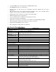
QoS Bandwidth control PoE Configuration Standards Conformance Network Standards Operating Temperature Storage Temperature Humidity Regulation Compliance Allow to assign low and high priority on each port Allow to assign rate control on each port Allow to Enable/Disable PoE function, setting power feeding priority, view PD power usage status. IEEE 802.3 (Ethernet), IEEE 802.3u (Fast Ethernet) IEEE 802.3z(Gigabit Ethernet) IEEE 802.3ab (Gigabit Ethernet) IEEE802.3x (Flow control) IEEE 802.1p QoS IEEE802.
# &''& This section describes the functionalities of FGSW-2402PVS/ FGSW-2620PVS components and guides how to install it on the desktop or shelf. Basic knowledge of networking is assumed. Please read this chapter completely before continuing. $ The PLANET Switch provides 24 10/100Mbps Fast Ethernet ports with 2 open slots or 2 fixed 10/100/1000Mbps ports (port25, 26).
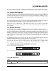
LED Color Function LNK/ACT Green Lit: indicate the link through that port is successfully established. Blink: indicate that the switch is actively sending or receiving data over that port. 100 Orange Lit: indicate that the port is operating at 100Mbps. Off: indicate that the port is operating at 10Mbps.
Note: When choosing a location, please keep in mind the environmental restrictions discussed in Chapter 1, Section 4, Specification. Step4: Connect your Switch to network devices A. Connect one end of a standard network cable to the 10/100 RJ-45 ports on the front of the Switch. B. Connect the other end of the cable to the network devices such as printer servers, workstations or routers…etc. Note: Connection to the Switch requires UTP Category 5 network cabling with RJ-45 tips.
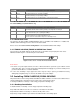
Figure 2-5 Mounting the Switch in a Rack Step6: Proceed with the steps 4 and steps 5 of section 2.2.1 Desktop Installation to connect the network cabling and supply power to your Switch.
# '0 !) & Unlike the unmanaged switch, FGSW-2402PVS/ FGSW-2620PVS performs series smart functions that make the Switch operate more effectively. This section will describe the common usage of the Switch Smart Configuration. Note: The following section will base on the console screens of FGSW-2620PVS, for FGSW-2402PVS the display will be the same to FGSW-2620PVS.
Figure 3-2 Power-up System Self-diagnostic screen "' After the self-test completes successfully, the screen in figure 3-3 appears. Login is required to access the console interface. The factory default username is "admin" without password. You may change it in the Misc Configuration. To access to the Main Menu, please always enter the correct username and password. Figure 3-3 Switch Console Login screen ) # ) ) Switch allows users to configure the device via menu screens.
Figure 3-4 Main Menu Screen 1. Port Status Display the port status, which allow you to view the port disable/enable status, current link status, speed/duplex mode, flow control status. Explained in section 3.2.3. 2. Port Configuration Allow user to disable/enable each port, Auto-negotiation disable/enable on each port, per port 10/100Mbps full and half duplex mode selection. Flow control disable/enable on each port. Explained in section 3.2.4. 3.
Figure 3-5 Port Status Screen O Object Port Enable Link Spd/Dpx Flow Ctrl Description Indicate port 1 to port 24, and 2-module slot. Display disable or enable on each port. Display current link status on each port. Display current speed duplex mode on each port. Display current flow control status on each port.
Note: 1. xx represents the maximum fiber-optic distance, for example MII-L40 for 40kilometers. For the available models, please consult your local dealer for the available modules. 2. For fiber module/interface, please also check the link partner is set to forced full-duplex for the connection.
Object Description VLAN Configuration Allow user to disable/enable the Port-based VLAN function. The available options are shown as below: Disabled: disable VLAN function of the Switch. PortBased: enable port-based VLAN function of the Switch. The available group ID from 1 to 255. Return to Main Menu Back to Main Menu screen. Table 3-6 Descriptions of the VLAN Configuration screen Objects 3.2.6.1 Create a Port-Based VLAN Group Choose “PortBased” from the VLAN mode of VLAN Configure.
Figure 3-12 Create a port-based VLAN Group screen Press “Enter” then the following screen in figure 3-13 appears. Figure 3-13 Create a port-based VLAN Group screen Use the "TAB" key to move the highlight to the Add and press “Enter” to access the screen of Add a PortBased VLAN Group. Use the "TAB" key to move the highlight to the and press “Enter” to modify these settings.
Figure 3-16 Create a port-based VLAN Group completed screen 3.2.6.2 Edit a VLAN Group Use the "TAB" key to move the highlight to the and press “Enter” to start editing the existence VLAN group. The screen in figure 3-17 appears. Figure 3-17 Edit existence VLAN Group Configuration Screen Use the “Tab” and “Back space” to move forth and back between VLAN and press “Enter” to select the VLAN you want to edit. The screen in figure 3-18 appears. Please follow the same procedure as section 3.2.6.
3.2.6.3 Delete a VLAN Group Use the "TAB" key to move the highlight to the and press "Enter" to start the deleting of existence VLAN group. The screen of Delete a VLAN Group in figure 3-20 appears. Figure 3-20 Delete existence VLAN group Screen Use “TAB” or “Backspace” key to move the highlight to the VLAN you want to delete and press “Enter” to delete the VLAN. The screen similar to figure 3-21 appears with message “ Press Enter to edit/delete group”.
Figure 3-24 Delete existence VLAN Group successfully Screen 3.2.6.4 Return to Main Menu Choose “Return to Main Menu” to return to Main Menu screen of the Switch. The screen in figure 3-25 appears. Figure 3-25 Return to Main Menu Screen 4 % Press 5 on your keyboard or use the "TAB" key to move the highlight to the Port Mirroring Configuration and press “Enter” to access the screen of Port Mirroring Configuration from the Main Menu screen (please see the figure 3-4).
Monitoring Port Allow seeing all monitor port traffic; you can connect Monitoring port to LAN Explorer, Session Wall, Sniffer Pro or Netxray. Monitored Port Choose one or more specific port for monitor the traffic of RX and TX or both (RX and TX) from Monitoring port. Table 3-7 Descriptions of the Port Mirroring Configuration Screen Objects After setup is completed. Press "ESC" key to return to Actions menu and use the "TAB" key to choose the for saving the current configuration.
After setup is completed. Press "ESC" key to return to Actions menu and use the "TAB" key to choose the for saving the current configuration. The screen in figure 3-29 appears with message “Operation completed successfully!” Figure 3-29 QoS Configuration save successfully screen 78 Press 7 on your keyboard or use the "TAB" key to move the highlight to the Bandwidth control and press “Enter” to access the screen of Bandwidth control from the Main Menu screen (please see the figure 3-4).
, % Press 8 on your keyboard or use the "TAB" key to move the highlight to the Misc Configuration and press “Enter” to access the screen of Misc Configuration from the Main Menu screen (please see the figure 3-4). Table 3-10 shows the descriptions of the Misc Configuration screen Objects. The screen of Misc Configuration in figure 3-32 appears. O Object Figure 3-32 Misc Configuration Screen Description Advanced Switch Configuration Allow user to configure the advanced Switch configuration.
O Object Description Broadcast Strom Filter Collision Retry Forever MAC Table Auto-Aging MAC Table Hashing If this function enable, the Switch will limitation the broadcast packets. The available options are Off, 5%, 10%, 20%. If this function is disabled, when a packet meet a collision, the switch will retry 6 times before discard the packets. Otherwise, the switch will retry until the packet is successfully sent. Allow user to set the aging time of the MAC address table.
O Object Description Password protection Allow user to disable or enable the password request of the console and Web interface. User Name Allow user to modify the login user name. Up to 8 characters. New Password Allow user to modify the login password. Up to 8 characters. Password Again Input the password again for confirm. Table 3-12 Descriptions of the Password Setting screen Objects After setup is completed.
Figure 3-39 Reboot Switch Screen Figure 3-40 Switch Console Login Screen 3.2.10.4 Reboot System Press 4 on your keyboard or use the "TAB" key to move the highlight to the Reboot System and press “Enter” from the Misc Configuration screen (please see the figure 3-32). The screen in figure 3-41 appears with message “Reboot now? [Y/N] ”. Press “Y” then the Switch will reboot, the screen in figure 3-42 appears. After power on completed, then the login screen of Switch in figure 3-43 appears.
Figure 3-43 Switch Console Login Screen 3.2.10.5 System Information Press 5 on your keyboard or use the "TAB" key to move the highlight to the System Information and press “Enter” from the Misc Configuration screen (please see the figure 3-32). The screen in figure 3-44 appears. Figure 3-44 System Information Screen 3.2.10.
After setup is completed. Press "ESC" key to return to Actions menu and use the "TAB" key to choose the for saving the current configuration. The screen in figure 3-46 appears with message “Operation completed successfully!” Figure 3-46 IP Configuration Screen 3.2.10.7 Return to Main Menu This function allows user to return to the main menu of Switch. The screen in figure 3-47 appears. Then the main menu in screen figure3-48 appears.
O Object Description POE Ports Config POE Port Status Return to Main Menu Allow user to configure the POE function and power provision priority. Please refer to chapter 3.2.11.1. Allow user to check the POE PD power usages. Please refer to chapter 3.2.11.2. Allow return to the Console Main Menu. Please refer to chapter 3.2.11.3. Table 3-14 Descriptions of the Switch Information screen Objects 3.2.11.
O Object Description Port List the port number for configuration. Enable List each port POE power provision setting. Power [W] List each connected device power usage. Current [mA] List each connected device current usage. Table 3-16 Descriptions of the POE Port Status screen Objects 3.2.11.3 Return to Main Menu This function allows user to return to the main menu of Switch. The screen in figure 3-52 appears. Then the main menu in screen figure3-53 appears.
" * 08 !) & The Web Smart Ethernet Switch provides a Web interface for Switch Smart function configuration. Since the Switch can be configured through the Web Browser, a network administrator can manage and monitor the Switch from the local LAN or from the Internet. Before login the Web interface of Switch, please setup the “IP Address” with local serial console port (RS232 port) and use this IP address to configure Switch through the Web interface.
Port Configuration: Allow user to disable/enable each port, Auto-negotiation disable/enable on each port, per port 10/100Mbps full and half duplex mode selection. Flow control disable/enable on each port. Explained on section 4.4 Trunk Configuration: Allow user to enable the trunk function and configure. Explained in section 4.5 VLAN Configuration: Allow user to enable the port-based VLAN function and configure. Explained in section 4.
Figure 4-4 Port Configuration Screen After setup is completed. Press "Apply" button for save the current configuration. The screen figure 4- 5 appears with message “Operation completed successfully!” Please be reminded, the operation of port#25, port#26 will base on the setting in table 3-4. Figure 4-5 Port Configuration save successfully Screen Press “Back” for back to previous web screen. "2 % This function allows to configuring the trunk function.
" / -'& % This function allows to enabling the port-based VLAN function. The screen in figure 4-8 appears. Figure 4-8 VLAN Configuration Screen After setup is completed. Press "Apply" button for enable the port-based VLAN. The screen in figure 4- 9 appears Figure 4-9 VLAN Configuration Screen Press “Add NEW” to create a new port-based VLAN group. The screen in figure 4-10 appears. Note: Up to 26 port-based VLAN groups can be added and the group ID range is 1-255.
Figure 4-11 VLAN Configuration save successfully Screen Press “Back” for back to previous web screen. It also support delete the existence VLAN group by press “Delete” button from VLAN Configure screen (figure 4-9). "4 % This function allows to enabling the port mirroring function. Table 4-1 shows the descriptions of the Port Mirroring Configuration screen Objects. O Object Description Disable port mirroring function.
Figure 4-14 Port Mirroring Configuration save successfully Screen Press “Back” for back to previous web screen. "56 # % This function allows enabling the QoS function. Table 4-2 shows the descriptions of the QoS Configuration screen Objects. O Object Description Disable QoS priority function. Disable QoS Priority High empty then Low Forward the packets with high priority first then packets with low priority. The packet output ration of high priority and low priority is 3 to 1.
Figure 4-17 QoS Configuration Screen After setup is completed. Press "Apply" button for save the current configuration. The screen in figure 4-18 appears with message “Operation completed successfully!” Figure 4-18 QoS Configuration save successfully Screen Press “Back” for back to previous web screen. "78 This function allow to set bandwidth on each port. Table 4-3 shows the descriptions of the Bandwidth Control screen Objects.
Figure 4-20 Bandwidth Control save successfully Screen Press “Back” for back to previous web screen. " , % This function provides the advanced configuration of the Switch. The available options are shown as below: Advanced Switch Configuration: Allow user to configure the advanced Switch configuration. Please refer to section 4.10.1. Password Setting: Allow user to disable or enable password protection. Set the username and password, Maximum up to 8 characters. Please refer to section 4.10.2.
Figure 4-22 Broadcast Storm Filter Screen Collision Retry Forever: If this function is disabled, when a packet meet a collision, the switch will retry 6 times before discard the packets. Otherwise, the switch will retry until the packet is successfully sent. The screen in figure 4-23 appears. Figure 4-23 Collision Retry Forever Screen MAC Table Auto-Aging: Allow user to set the aging time of the MAC address table. The available options are Disable, 150 sec, 300 sec, 600 sec. The default is 300sec.
Figure 4-26 Console Auto Logout Time Screen Web Auto Logout Time: Allow user to set the Auto logout time of web interface. The available options are 5min, 10min, and 20min. The screen in figure 4-27 appears. Figure 4-27 Web Auto Logout Time Screen After setup is completed. Press "Apply" button for save the current configuration.
The screen in figure 4-29 appears. Figure 4-29 Password Setting Screen If disable the password protection. Then the following screen appears. Figure 4-30 Password Setting Screen Press, “OK” for logout the Switch. Then can enter into the web interface of the Switch without any username and password request. If enable the password protection. Then the following screen appears. Figure 4-31 Password Setting Screen Press, “OK” for re-login the Switch.
Figure 4-32 Password Setting save successfully Screen Press “Back” for back to previous web screen. " , #9 3 % # This function allows resetting the Switch to default mode. The screen in figure 4-33 appears. Press “OK” then the Switch will reboot for the default mode. Figure 4-33 Reset System Default Setting Screen " ," : #9 3 This function allows rebooting the Switch. The screen in figure 4-34 appears. Press “OK” then the Switch will reboot.
Figure 4-35 System Information Screen " ,/ % This function allows modifying the IP address, subnet mask and default gateway. The screen in figure 4-36 appears. Note: The default IP address is 192.168.0.100 Figure 4-36 IP Configuration Screen After setup is completed. Press "Apply" button for save the current configuration.
POE Port Status: Allow user to check the port Power over Ethernet settings and the connected power usage. Please refer to section 4.11.2. " 0 This function allows Enable/Disable POE function and set port power feeding priority. The screen in figure 4-38 appears. Figure 4-38 POE Configuration Screen After setup is completed. Press "Apply" button for save the current configuration.
" ' This function allows to logout the web interface of the Switch. The screen in figure 4-41 appears. Press “OK” then the web login screen in figure 4-42 appears.
2 #* 2 & 0 & : The Switch is implemented with an address table. This address table composed of many entries. Each entry is used to store the address information of some node in network, including MAC address, port no, etc. This information comes from the learning process of Ethernet Switch. 2 ' When one packet comes in from any port, the Switch will record the source address, port no. And the other related information in address table.
/ 8'0# ) This chapter contains information to help you solve problems. If the Ethernet Switch is not functioning properly, make sure the Ethernet Switch was set up according to instructions in this manual. The Link LED is not lit Solution: Check the cable connection and remove duplex mode of the Ethernet Switch Some stations cannot talk to other stations located on The other port Solution: Please check the VLAN settings, trunk settings, or port enabled / disabled status.
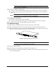
& & # = >+"2 & 1000Mbps, 1000Base T 0 <& 3 Contact MDI MDI-X 1 BI_DA+ BI_DB+ 2 BI_DA- BI_DB- 3 BI_DB+ BI_DA+ 4 BI_DC+ BI_DD+ 5 BI_DC- BI_DD- 6 BI_DB- BI_DA- 7 BI_DD+ BI_DC+ 8 BI_DD- BI_DC- Implicit implementation of the crossover function within a twisted-pair cable, or at a wiring panel, while not expressly forbidden, is beyond the scope of this standard. & ,. ,, :$ ? ,.
Figure A-1: Straight-Through and Crossover Cable Please make sure your connected cables are with same pin assignment and color as above picture before deploying the cables into your network.