24-Port 10/100Mbps with 2-Gigabit Web Smart Ethernet Switch FGSW-2402VS/FGSW-2620VSF User’s Manual -1-
Trademarks Copyright © PLANET Technology Corp. 2006. Contents subject to revision without prior notice. PLANET is a registered trademark of PLANET Technology Corp. All other trademarks belong to their respective owners. Disclaimer PLANET Technology does not warrant that the hardware will work properly in all environments and applications, and makes no warranty and representation, either implied or expressed, with respect to the quality, performance, merchantability, or fitness for a particular purpose.
TABLE OF CONTENTS 1. INTRODUCTION.......................................................................................................................................... 4 1.1 CHECKLIST ................................................................................................................................................ 4 1.2 ABOUT THE SWITCH ................................................................................................................................... 4 1.3 FEATURES .........
1. INTRODUCTION 1.1 Checklist Check the contents of your package for following parts: z FGSW-2402VS or FGSW-2620VSF x1 z User's manual CD x1 z Quick installation guide x1 z Power cord x 1 z Rubber feet x 4 z Rack mount accessory x 1 If any of these pieces are missing or damaged, please contact your dealer immediately, if possible, retain the carton including the original packing material, and use them against to repack the product in case there is a need to return it to us for repair.
1.3 Features ◆ Complies with the IEEE 802.3, IEEE 802.3u, IEEE 802.3z and IEEE 802.
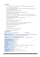
Temperature Operating: 0~50 degree C, Storage -40~70 degree C Humidity Operating: 10% to 90%, Storage: 5% to 95% (Non-condensing) Smart function System Configuration Web interface Port Status Display per port’s disable/enable status, per port’s link status and speed duplex mode. Also the Flow control status Port Configuration Per port disable/enable, Auto-negotiation disable/enable. 10/100Mbps full and half duplex mode selection.
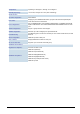
2. HARDWARE DESCRIPTION This product provides three different running speeds – 10Mbps, 100Mbps and 1000Mbps in the same Web Smart Switch and automatically distinguishes the speed of incoming connection. This section describes the hardware features of Web Smart Switch. For easier management and control of the Web Smart Switch, familiarize yourself with its display indicators, and ports. Front panel illustrations in this chapter display the unit LED indicators.
#Notice: 1. Press the RESET button once. The Web Smart Switch will reboot automatically. 2. Press the RESET button for 5 seconds. The Web Smart Switch will back to the factory default mode; the entire configuration will be erased. 3. The FGSW-2402VSv2 must work with MII-V series module for 100Base-FX fiber connection. 3. The 2 Gigabit TP/SFP combo ports are shared with port 25/26 of FGSW-2620VSF. Either of them can operate at the same time. 2.
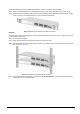
To install the Web Smart Switch in a 19-inch standard rack, follow the instructions described below. Step 1: Place your Web Smart Switch on a hard flat surface, with the front panel positioned towards your front side. Step 2: Attach a rack-mount bracket to each side of the Web Smart Switch with supplied screws attached to the package. Figure 2-4 shows how to attach brackets to one side of the Web Smart Switch.
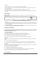
3. SWITCH MANAGEMENT This chapter describes how to manage the Web Smart Switch. Topics include: - Overview - Management method - Logging on to the Web Smart Switch 3.1 Overview The Web Smart Switch provides a user-friendly, web interface. Using this interface, you can perform various switch configuration and management activities, including: Please refer to the following Chapter 4 for the details. 3.
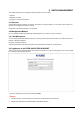
4. WEB MANAGEMENT To modify your PC’s IP domain to the same with Web Smart Switch then use the default IP address (192.168.0.100) to remote configure Web Smart Switch through the Web interface. #Notice: The following section will base on the console screens of FGSW-2620VSF, for FGSW-2402VS the display will be the same to FGSW-2620VSF. 4.1 Login in to the Switch To access the Web-browser interface you must first enter the user name and password, the default user name and password is "admin”.
Figure 4-2 Web main menu screen 4-2 Port Status This section provides current status of each port from Web Smart Switch, the screen in Figure 4-3 appears and table 4-1 describes the port status object of Web Smart Switch.
Object Description Port Indicate port 1 to port 26. Enable Display the port Disable or Enable state of each port on Web Smart Switch. Link Status Spd/Dpx The state of the link, indicating a valid link partner device. "Up" means a device is successful connected to the port. “Down” means no device is connected. Display the Speed duplex mode of each port on Web Smart Switch. Flow Control Display the flow control On or Off state of each port on Web Smart Switch.
Figure 4-5 Port Configuration Web Page screen Object Description Port Indicate port 1 to port 26. Enable Per port Disable or Enable on Web Smart Switch. Auto Per port Disable (Off) or enable (On) Auto negotiation on Web Smart Switch. Adjust per port speed duplex mode on Web Smart Switch; the available options are Auto, 100F, 100H, 10F, 10H. Default mode is Auto. Flow Control Per port Flow control Disable (Off) or enable (On) on Web Smart Switch. Default mode is On.
4-4 Trunk configuration This function allows to configuring the trunk function. It provides up to 7 trunk groups and each trunk group provides 2 to 8 member ports. Please check the member port from “Normal” to 7 trunk groups and the screen in Figure 4-6 & 4-7 appears. Figure 4-6 Trunk Configuration Web Page screen Figure 4-7 Trunk Configuration Web Page screen After setup completed, please press “Apply” button to take effect and the screen in Figure 4-8 appears.
Figure 4-8 Trunk Configuration Web Page screen Please press “Back” for return to Trunk configuration screen for further configuration. If the member port from each trunk group is out of range or less than 2 ports than the following screen appears. Figure 4-9 Trunk Configuration Web Page screen Please press “Back” for return to Trunk configuration screen for adds other trunk group.
4-5 VLAN configuration A Virtual LAN (VLAN) is a logical network grouping that limits the broadcast domain. It allows you to isolate network traffic so only members of the VLAN receive traffic from the same VLAN members. The Web Smart Switch supports 26 port-based VLAN groups. In the default configuration with VLAN disable, the screen in Figure 4-10 appears. Figure 4-10 Port-based VLAN Setting Web Page screen 4.5.
Figure 4-11 Port-based VLAN Setting Web Page screen Press “Relogin” to re-login the Web Smart Switch and the screen in Figure 4-12 appears. Figure 4-12 Port-based VLAN Setting Web Page screen After login web interface of Web Smart Switch and choose VLAN configuration, the screen in Figure 4-13 appears.
Press “AddNew” button to add a port-based VLAN group and setup procedure is shown as below: 1. Input a VLAN group ID and available range is 1-4094. 2. Select specific port as member port and the screen in Figure 4-14 appears. 3. After setup completed, please press “Apply” button to take effect and the screen in Figure 4-15 appears. 4. Please press “Back” for return to VLAN configuration screen to add other VLAN group, the screen in Figure 4-16 appears.
Figure 4-16 Port-based VLAN Setting Web Page screen 4.5.
1. Select specific port as member port and the screen in Figure 4-17 appears. 2. After setup completed, please press “Apply” button to take effect and the screen in Figure 4-18 appears. 3. Please press “Back” for return to VLAN configuration screen to continue VLAN configuration. Figure 4-17 Edit Port-based VLAN Setting Web Page screen Figure 4-18 Edit Port-based VLAN Setting Web Page screen 4.5.
1. Check existence VLAN group ID and the screen in Figure 4-19 appears. 2. Press “Delete” button to delete existence port-based VLAN group. 3. Then the “Delete all checked groups” window appears, please press “OK” to continue the delete VLAN group procedure and the screen in Figure 4-20 appears. 4. Please press “Back” for return to VLAN configuration screen to continue VLAN configuration. The screen in Figure 4-21 & 4-22 appears.
Figure 4-21 Delete Port-based VLAN group Web Page screen Figure 4-22 Port-based VLAN group Web Page screen 4.5.4 Disable port-based VLAN function Select “Disable” and pop window appears, press “OK” to disable the port-based VLAN function then the Web Smart Switch will reboot for take affect. The screen in Figure 4-23 & 4-24 & 4-25 & 4-26 & 4-27 appears.
Figure 4-23 Disable Port-based VLAN function Web Page screen Figure 4-24 Disable Port-based VLAN function Web Page screen - 24 -
Figure 4-25 Disable Port-based VLAN function Web Page screen Figure 4-26 Disable Port-based VLAN function Web Page screen - 25 -
Figure 4-27 Disable Port-based VLAN function Web Page screen 4-6 Port Monitoring This function provide to monitoring network traffic that forwards a copy of each incoming or outgoing packet from one port of a network Switch to another port where the packet can be studied. It enables the manager to keep close track of switch performance and alter it if necessary. The screen in Figure 4-28 appears and table 4-3 describes the port Monitoring object of Web Smart Switch.
Figure 4-28 Port Monitoring Web Page screen Object Description Port Monitoring Mode Provide Disable, RX, TX and RX & TX different modes for port Monitoring function. Default mode is Disable. Monitoring Port The monitoring port can be used to see all monitor port traffic. It can connect monitoring port to LAN analyzer or Netxray. The monitored port that want to monitor. All monitor port traffic will be copied to mirror port. It can select 1 monitored port in the Web Smart switch.
4-7 QoS Configuration This function provides QoS Configuration of Web Smart Switch, the screen in Figure 4-29 appears and table 4-4 descriptions the QoS Configuration of Web Smart Switch.
Figure 4-30 QoS Configuration Web Page screen Figure 4-31 QoS Configuration Web Page screen - 29 -
Figure 4-32 QoS Configuration Web Page screen 4-8 Port counters This function could provide you with an individual statistical counter; it is a useful page for administrator to monitor each port’s usage condition. Also, it is helpful to troubleshooting network problems. The screen in Figure 4-33 & 4-34 appears.
Figure 4-33 Port Counters Web Page screen Figure 4-34 Port Counters Web Page screen Press “ClearAllCntr” button to refresh current per port counters on Web Smart Switch.
4-9 Access Control List The Access Control List (ACL) is a concept in computer security used to enforce privilege separation. It is a means of determining the appropriate access rights to a given object depending on certain aspects of the process that is making the request, principally the process's user identifier.
Figure 4-36 Access Control List (ACL) Web Page screen Figure 4-37 Access Control List (ACL) Web Page screen - 33 -
Figure 4-38 Access Control List (ACL) Web Page screen Figure 4-39 Access Control List (ACL) Web Page screen - 34 -
Figure 4-40 Access Control List (ACL) Web Page screen Figure 4-41 Access Control List (ACL) Web Page screen - 35 -
Figure 4-42 Access Control List (ACL) Web Page screen Figure 4-43 Access Control List (ACL) Web Page screen - 36 -
Figure 4-44 Access Control List (ACL) Web Page screen Figure 4-45 Access Control List (ACL) Web Page screen - 37 -
Figure 4-46 Access Control List (ACL) Web Page screen Figure 4-47 Access Control List (ACL) Web Page screen - 38 -
Figure 4-48 Access Control List (ACL) Web Page screen Figure 4-49 Access Control List (ACL) Web Page screen - 39 -
4-10 Web Smart Function This function could provide you to define device indicate connect to each port on Web Smart Switch, the screen in Figure 4-50 appears. Figure 4-50 Web Smart Funciton Web Page screen The available options are shown as below: 1. PC 2. PC+Voip 3. Switch 4. Router 5. AP 6. Server 7. Printer 8. Guest 9. Other The screen in Figure 4-51 appears and the setup procedure shown as below: 1.
Figure 4-51 Web Smart Funciton Web Page screen Figure 4-52 Web Smart Funciton Web Page screen - 41 -
Figure 4-53 Web Smart Funciton Web Page screen This function also provides Apply for all ports option from Select a port function, the setup procedure shown as below: 1. Choose a device and check “Apply for all ports” from options of Select a port function, the screen in Figure 4-54 appears. 2. Check any port then all port will be select; the screen in Figure 4-55 appears. 3. After setup completed, press “Save” to save current configuration, the screen in Figure 4-56 appears. 4.
Figure 4-54 Web Smart Funciton Web Page screen Figure 4-55 Web Smart Funciton Web Page screen - 43 -
Figure 4-56 Web Smart Funciton Web Page screen Figure 4-57 Web Smart Funciton Web Page screen - 44 -
4-11 Misc Operation This section provide Misc Operation of Web Smart Switch, the screen in Figure 4-58 appears and table 4-6 descriptions the Misc Operation objects of Web Smart Switch. Figure 4-58 Misc Operation Web Page screen Object Description Switch Configuration Provide Advanced Switch Configuration and available options are Broadcast Storm Filter. Collision Retry Forever. MAC Table Auto-Aging. MAC Table Hashing. Web Auto Logout Time. Please refer to section 4.11.1 for detail description.
4.11.1 Switch Configuration Choose Switch Configuration from Misc Operation of Web Smart Switch( please see the Figure 4-58) , the screen in Figure 4-59 appears and table 4-7 descriptions the Switch Configuration from Misc Operation of Web Smart Switch. Figure 4-59 Switch Configuration Web Page screen Object Description Broadcast Storm Filter Provide Broadcast storm filter function and available options are Off. 1/2. MAC 1/4. 1/8.1/16. Default mode is Off; the screen in Figure 4-59 appears.
Figure 4-60 Switch Configuration Web Page screen Figure 4-61 Switch Configuration Web Page screen - 47 -
Figure 4-62 Switch Configuration Web Page screen Figure 4-63 Switch Configuration Web Page screen - 48 -
4.11.2 TFTP Firmware Upgrade This section provides Firmware upgrade through TFTP method on Web Smart Switch, the screen in Figure 4-64 appears.
4.11.3 Password Setting This section provides password setting of Web Smart Switch, the screen in Figure 4-65 appears and table 4-8 descriptions the Password Setting. Figure 4-65 Password Setting Web Page screen Object Description Password Protection Provide Password protection function”Disable” or”Enable” on Web Smart Switch; Default mode is Enable. Provide to modify password on Web Smart Switch and maximum up to six characters. Default User Name is admin.
4.11.4 IP Configuration This section provides IP Configuration on Web Smart Switch; the screen in Figure 4-66 appears and tables 4-9 descriptions the IP Configuration. Figure 4-66 IP Configuration Web Page screen MAC Address Display MAC address on Web Smart Switch. IP Address Provide to modify IP Address on Web Smart Switch. Default IP address is 192.168.0.100. Subnet Mask Provide to modify Subnet Mask on Web Smart Switch. Default Subnet Mask is 255.255.255.0.
4.11.5 Factory Default This section provides Factory Default function on Web Smart Switch, after choose this function and the following screen appears in Figure 4-67. Please press “OK” button to take effect and the switch will reset to factory default mode and ask you to waiting rebooting around 10 sec, press “OK” button to re-login the Web Smart Switch. The screen in Figure 4-68 & 4-69 & 4-70 appears.
Figure 4-69 Factory Default Web Page screen Figure 4-70 Factory Default Web Page screen - 53 -
4.11.6 Reboot System This section provides Reboot function on Web Smart Switch, after choose this function and the following screen appears in Figure 4-71. Please press “OK” button to take effect and the switch will reboot and ask you to waiting rebooting around 10 sec, press “OK” button to re-login the Web Smart Switch. The screen in Figure 4-72 & 4-73 & 4-74 appears.
Figure 4-73 Reboot Web Page screen Figure 4-74 Reboot Web Page screen - 55 -
4.11.7 System Information This section display system information on Web Smart Switch, after choose this function and the following screen appears in Figure 4-75.
4-12 Logout This section provide web logout function on Web Smart Switch, after choose this function and the following screen appears in Figure 4-76. Please press “OK” button to take effect and Logout pop window appears, press “OK” button to re-login the Web Smart Switch. The screen in Figure 4-77 & 4-78 & 4-79 appears.
Figure 4-77 Logout Web Page screen Figure 4-78 Logout Web Page screen - 58 -
Figure 4-79 Logout Web Page screen - 59 -
5. SWITCH OPERATION 5.1 Address Table The Switch is implemented with an address table. This address table composed of many entries. Each entry is used to store the address information of some node in network, including MAC address, port no, etc. This information comes from the learning process of Ethernet Switch. 5.2 Learning When one packet comes in from any port. The Switch will record the source address, port no. And the other related information in address table.
6.TROUBLESHOOTING This chapter contains information to help you solve problems. If the Switch is not functioning properly, make sure the Ethernet Switch was set up according to instructions in this manual. The Link LED is not lit Solution: Check the cable connection and remove duplex mode of the Switch. Some stations cannot talk to other stations located on the other port Solution: Please check the VLAN, port trunking function that may introduce this kind of problem.
APPENDIX A NETWORKING CONNECTION A.
There are 8 wires on a standard UTP/STP cable and each wire is color-coded. The following shows the pin allocation and color of straight cable and crossover cable connection: Figure A-1: Straight-Through and Crossover Cable Please make sure your connected cables are with same pin assignment and color as above picture before deploying the cables into your network.