4-Port 10/100Mbps + 2-Port Gigabit Ethernet Switch FGSW-2620 User’s Manual
Trademarks Copyright © PLANET Technology Corp. 2007. Contents subject to revision without prior notice. PLANET is a registered trademark of PLANET Technology Corp. All other trademarks belong to their respective owners. Disclaimer PLANET Technology does not warrant that the hardware will work properly in all environments and applications, and makes no warranty and representation, either implied or expressed, with respect to the quality, performance, merchantability, or fitness for a particular purpose.
FCC Warning This equipment has been tested and found to comply with the limits for a Class A digital device, pursuant to Part 15 of the FCC Rules. These limits are designed to provide reasonable protection against harmful interference when the equipment is operated in a commercial environment. This equipment generates, uses, and can radiate radio frequency energy and, if not installed and used in accordance with the Instruction manual, may cause harmful interference to radio communications.
TABLE OF CONTENTS 1. Introduction................................................................................ 5 1.1 Package Contents................................................................. 5 1.2 How to Use This Manual ...................................................... 5 1.3 Product Features.................................................................. 6 1.4 Product Specifications........................................................... 7 2. Installation................................
1. Introduction 1.1 Package Contents Check the contents of your package for following parts: ● 24-Port 10/100Mbps+ 2-Port Gigabit Ethernet Switch x1 ● User's manual x1 ● Power cord x1 ● Two Rack-Mounting Brackets with Attachment Screws x1 If any of these are missing or damaged, please contact your dealer immediately, if possible, retain the carton including the original packing material, and use them against to repack the product in case there is a need return to it to us for repairing. 1.
1.3 Product Features ● Comply with the IEEE 802.3, IEEE 802.3u, IEEE 802.3ab, IEEE 802.3z Gigabit Ethernet standard ● 24-Port 10/100Mbps Fast Ethernet ports ● 2 10/100/1000Mbps ports ● Each Switching ports support auto-negotiation-10/20, 100/200Mbps, 1000/2000Mbps supported ● Auto-MDI/MDI-X detection on each RJ-45 port ● Prevents packet loss with back pressure (half-duplex) and IEEE 802.
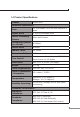
1.4 Product Specifications Product FGSW-2620 Hardware Specification Ports 24 10/100Base-TX RJ-45 Auto-MDI/MDI-X ports Gigabit ports 2 10/100/1000Mbps ports Switch Processing Scheme Store-and-Forward Throughput (packet per second) 6.54Mpps Switch fabric 8.8Gbps Address Table 4K entries Share data Buffer 2.5Mbits Flow Control Back pressure for half duplex, IEEE 802.3x Pause Frame for full duplex Dimensions 440 x 120 x 44 mm (1U height) Weight 1.
2. Installation This section describes the functionalities of FGSW-2620 components and guides how to install it on the desktop or shelf. Basic knowledge of networking is assumed. Please read this chapter completely before continuing. 2.1 Product Description The PLANET FGSW-2620 provides 24 10/100Mbps Fast Ethernet ports with 2 10/100/1000Mbps ports (port 25/26). The two Gigabit ports can be 1000Base-T for 10/100/1000Mbps; the distance can be extended from 100 meters (TP).
2.1.3 LED Indicators System LED Color PWR Green Function Lights to indicate that the Switch is powered on. Per 10/100Mbps port LED LNK/ACT 10/100 Color Function Green Lights: to indicate the link through that port is successfully established. Blink: indicate that the Switch is actively sending or receiving data over that port. Steady Lights: to indicate the port is run at 100Mbps. Orange Blinking Slowly: to indicate the port is run at 10Mbps.
2.1.4 FGSW-2620 Rear Panel The rear panel of the Switch indicates an AC inlet power socket, which accepts input power from 100 to 240VAC, 50-60Hz. Figure 2-2 shows Rear panel of the Switch. Figure 2-2 Rear Panel of FGSW-2620 Power Notice: 1. The device is a power-required device, it means, it will not work till it is powered. If your networks should active all the time, please consider using UPS (Uninterrupted Power Supply) for your device. It will prevent you from network data loss or network downtime. 2.
Step3: Keep enough ventilation space between the Switch and the surrounding objects. Note Step4: When choosing a location, please keep in mind the environmental restrictions discussed in Chapter 1, Section 4, Specification. Connect your Switch to network devices A. Connect one end of a standard network cable to the 10/100 RJ-45 ports on the front of the Switch. B. Connect the other end of the cable to the network devices such as printer servers, workstations or routers…etc.
Step2: Attach a rack-mount bracket to each side of the Switch with supplied screws attached to the package. Figure 2-3 shows how to attach brackets to one side of the Switch. Figure 2-3 Attaching the brackets to the Switch Caution: You must use the screws supplied with the mounting brackets. Damage caused to the parts by using incorrect screws would invalidate your warranty. Step3: Secure the brackets tightly. Step4: Follow the same steps to attach the second bracket to the opposite side.
Step5: After the brackets are attached to the Switch, use suitable screws to securely attach the brackets to the rack, as shown in figure 2-4. Figure 2-4 Mounting the Switch in a Rack Step6: Proceed with the steps 4 and steps 5 of section 2.2.1 Desktop Installation to connect the network cabling and supply power to your Switch.
3. Switch Operation 3.1 Address Table The Switch is implemented with an address table. This address table composed of many entries. Each entry is used to store the address information of some node in network, including MAC address, port no, etc. This information comes from the learning process of Ethernet Switch. 3.2 Learning When one packet comes in from any port, the Switch will record the source address, port no. And the other related information in address table.
an internal buffer, do the complete error checking before transmission. Therefore, no error packets occurrence, it is the best choice when a network needs efficiency and stability. The Ethernet Switch scans the destination address from the packetheader, searches the routing table provided for the incoming port and forwards the packet, only if required. The fast forwarding makes the switch attractive for connecting servers directly to the network, thereby increasing throughput and availability.
If attached device is: 100Base-TX port will set to: • 10Mbps, no auto-negotiation 10Mbps • 10Mbps, with auto-negotiation 10/20Mbps (10Base-T/Full-Duplex) • 100Mbps, no auto-negotiation 100Mbps • 100Mbps, with autonegotiation 100/200Mbps (100Base-TX/FullDuplex) 16
4. Troubleshooting This chapter contains information to help you solve issues. If the Ethernet Switch is not functioning properly, make sure the Ethernet Switch was set up according to instructions in this manual. The per port LED is not lit Solution: Check the cable connection of the FGSW-2620. Performance is bad Solution: Check the speed duplex mode of the partner device. The FGSW-2620 is run at Auto-negotiation mode and if the partner is set to half duplex, then the performance will be poor.
Appendix A Networking Connection A.
A.2 RJ-45 cable Pin Assignments The standard RJ-45 receptacle/connector There are 8 wires on a standard UTP/STP cable and each wire is colorcoded. The following shows the pin allocation and color of straight cable and crossover cable connection: Figure A-1: Straight-Through and Crossover Cable Please make sure your connected cables are with same pin assignment and color as above picture before deploying the cables into your network.
This page is intentionally left blank