48-10/100Mbps + 4G Ethernet Web Smart Switch FGSW-4840S User’s Manual
Trademarks Copyright PLANET Technology Corp. 2004. Contents subject to revision without prior notice. PLANET is a registered trademark of PLANET Technology Corp. All other trademarks belong to their respective owners. Disclaimer PLANET Technology does not warrant that the hardware will work properly in all environments and applications, and makes no warranty and representation, either implied or expressed, with respect to the quality, performance, merchantability, or fitness for a particular purpose.
TABLE OF CONTENTS 1. INTRODUCTION ............................................................................................. ……………………1 1.1 PACKAGE CONTENTS ...................................................................................................................................................1 1.2 HOW TO USE THIS MANUAL ..........................................................................................................................................1 1.3 PRODUCT FEATURES ................
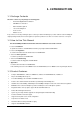
1. INTRODUCTION 1.1 Package Contents Check the contents of your package for following parts: ● Web Smart Gigabit Ethernet Switch x1 ● CD-ROM user's manual x1 ● Quick installation guide x1 ● 19” rack mounting kit x1 ● Power cord x1 ● Rubber feet x 4 If any of these are missing or damaged, please contact your dealer immediately, if possible, retain the carton including the original packing material, and use them against to repack the product in case there is a need to return it to us for repair.
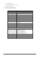
Support CSMA/CD protocol 100~240VAC, 50~60Hz universal Power input FCC, CE class A compliant 1.4 Product Specifications Model FGSW-4840S Hardware Specification 10/100Base-TX ports 48 10/100/1000Mbps ports 2 SFP-Mini-GBIC interfaces 2 Switch architecture Store-and-Forward Switch Fabric 17.6Gbps Switch throughput 13Mpps Address Table 4K entries Share data Buffer Flow Control 1536KBytes Back pressure for half duplex, IEEE 802.
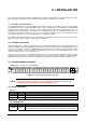
2. INSTALLATION This section describes the functionalities of FGSW-4840S’s components and guides how to install it on the desktop or shelf. Basic knowledge of networking is assumed. Please read this chapter completely before continuing. 2.1 Product Description The PLANET FGSW-4840S is a 10/100/1000Mbps Ethernet Switch provides 48 10/100Base-TX ports respectively with 2 10/100/1000Base-T ports and 2-SFP Mimi-GBIC interfaces. With a 17.
Per 1000Base-T port LED Color Function Lit: indicate the link through that port is successfully established. Blink: indicate that the switch is actively sending or receiving data over that port. LNK/ACT Green SPEED Green/orange Green: indicate that the port is operating at 1000Mbps. Orange: indicate that the port is operating at 100Mbps. Per SFP-Mini-GBIC port LED Color LNK/ACT Green Function Lit: indicate the link through that port is successfully established.
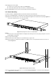
Step5: Supply power to the Switch. A. Connect one end of the power cable to the FGSW-4840S. B. Connect the power plug of the power cable to a standard wall outlet. When the FGSW-4840S receives power, the Power LED should remain solid Green. 2.2.2 Rack Mounting To install the switch in a 19-inch standard rack, follow the instructions described below. Step1: Place your FGSW-4840S on a hard flat surface, with the front panel positioned towards your front side.
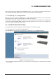
3. CONFIGURATION Unlike the unmanaged switch (Dumb switch), FGSW-4840S performs series smart functions that make the Switch operate more effectively. This Chapter will describe the common usage of the Switch’s Smart Configuration. 3.1 Preparing for configuration When you are ready to configure the smart functions of the Web Smart Gigabit Ethernet Switch. Please install the Web Switch utility and it can easily list the FGSW-4840S in your Ethernet environment.
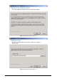
Figure 3-2 Web Switch Utility install process Figure 3-3 Web Switch Utility install process 7
Figure 3-4 Web Switch Utility install process Figure 3-5 Web Switch Utility install process 8
Figure 3-6 Web Switch Utility install process Figure 3-7 Web Switch Utility install completed 4. After install completed, choose Program Files -> PLANET Web Switch and execute the Web Switch utility. The screen in Figure 3-8 appears.
Figure 3-8 Web Switch Utility main screen The Web Switch Utility was divided into four parts, Toolbar function, Discovery List, Monitor List, Device Setting, please refer to the below section for the details instruction. 3.1.1.1 Toolbar function The toolbar in the Web Switch Utility provide four main tabs. File. View. Options. Help. 3.1.1.1.1 File In the “File TAB”, it provides Monitor Save, Monitor Save As, Monitor Load and Exit item.
Figure 3-9 Web Switch Utility’s File screen 3.1.1.1.2 View In the “View TAB”, it provides view log and clear log function, this function will help user to view the trap message. The detail explanation of each item is shown as below: View Log: to display the events of the FGSW-4840S. Clear Log: to clear the log of FGSW-4840S. Figure 3-10 Web Switch Utility’s View screen 3.1.1.1.
3.1.1.1.4 Help In the “Help TAB”, it provides “About” function, it display the version of the Web Switch Utility. Figure 3-12 Web Switch Utility’s Help screen 3.1.1.2 Discovery List This function allows user to list the FGSW-4840S in the entire network. By pressing the “Discovery” button, you can list the FGSW-4840S in the discovery list. Double click or press the “Add to monitor list” button to select a device from the Discovery List to the Monitor List. The screen in Figure 3-13 appears.
The Discovery List contains nine items: MAC Address: display the Switch MAC Address. IP Address: display the current IP address of the Switch. Protocol version: display the version of the Utility protocol. Product Name: display the Switch model name. System Name: display the appointed Switch system name. Location: display where the Switch is located. Trap IP: display the IP address where the Trap to be sent. Subnet Mask: display the Subnet Mask set of Switch. Gateway: display the Gateway set of the Switch.
Protocol version: display the version of the Utility protocol. Product Name: display the Switch model name. System Name: display the appointed Switch system name. Location: display where the Switch is located. Trap IP: display the IP address where the Trap to be sent. Subnet Mask: display the Subnet Mask set of the Switch. Gateway: display the Gateway set of the Switch. View Trap: The trap function can receive the events that happen from FGSW-4840S in the Monitor List.
Figure 3-16 Trap information screen In order to receive Trap information, the FGSW-4840S must configured with Trap IP and Trap Note: Events in Web interface. Please refer to chapter 3.1.2.9 Trap for detail information. Add Item: To add a device to the Monitor List manually, enter the IP Address of the device that want to monitor. Delete Item: To delete the device from the Monitor List. 3.1.1.4 Device Settings This function contains four items to setting the FGSW-4840S.
Firmware Upgrade: this function allows new firmware upgrade of FGSW-4840S. The screen in Figure 3-19 appears. Figure 3-19 Firmware Upgrade screen Firmware upgrade Procedure Step 1: Click “Browse” button to select the file where you have just saved in your workstation and ‘Choose file’ dialog box will appear, prompting you to select the file to upgrade the firmware. Step 2: Please input the correct password and click “Start” button to start replacing the latest Firmware revision.
Figure 3-21 Firmware Upgrade process screen Step 3: After firmware upgrade completed, the Switch will reboot automatically. Then the following screen in Figure 3-22 & 3-23 appears. Figure 3-22 Firmware Upgrade completed screen Figure 3-23 Firmware Upgrade successful screen After Switch power on completed. Then you can start to use the new firmware of FGSW-4840S.
3.1.2 Configure the FGSW-4840S The FGSW-4840S Web Smart Gigabit Ethernet Switch provide Web interface for Switch smart function configuration. The FGSW-4840S can be configured through the Web Browser. A network administrator can manage and monitor the FGSW-4840S from the local LAN. This section indicates how to configure the Switch to enable its smart function.
Figure 3-25 Web Main screen 3.1.2.3 Port This function allows displaying each port’s status. The Link Status in the screen displays the current connection speed and duplex mode; else this function will show “Down” when the port is disconnected. Press the “Refresh” button to renew the screen. The screen in Figure 3-26 appears. Figure 3-26 Port Setting screen Press the port ID to configure each port’s speed duplex mode and disable, flow control, QoS settings. The screen in Figure 3-27 appears.
Figure 3-27 Per Port Setting screen The options and descriptions of Port Settings shown as below: Speed: this function provides six modes—100M Full, 100M Half, 10M Full, 10M Half, Auto and Disable. When set each port to run at 100M Full, 100M Half, 10M Full, and 10M Half-speed modes. The Note: Auto-MDIX function will disable. Flow Control: this setting determines whether or not the Switch will be handling flow control. Set Flow Control to enable for avoiding data transfer overflow.
Figure 3-28 VLAN Setting screen To add a VLAN group, please press “Add Group” button, the new VLAN configuration screen will pop out, you can fill in the description in order to describe this VLAN Group, check on the port to be a member to this VLAN Group. There are two groups for VLAN Setting and only can choose one group in the same time, check on the port to be a member to the Port Group 1 or Port Group 2 then press “Apply” button to execute the setting. The screen in Figure3-29 appears.
Figure 3-30 Edit existence VLAN Setting screen Figure 3-31 Edit existence VLAN Setting screen After edit completed. Press “Apply” button to execute the setting. The screen in Figure 3-32 appears.
Figure 3-32 Edit existence VLAN Setting screen Delete the existence VLAN group. Press “Delete Group” button then the following screen appears. Figure 3-33 Delete existence VLAN group screen Press “Apply” button to execute the setting. The following screen in Figure 3-34 appears.
Figure 3-34 Delete existence VLAN group screen Note: The FGSW-4840S supports 26 port-based VLAN groups. Due to the hardware restriction. The port-based VLAN function cannot across between port 1-24 and port 25-52. 3.1.2.5 Trunking This function provide to cascade two Switch devices with a double bandwidth (maximum up to 4000Mbps in full duplex mode). There are seven trunk groups and each group provides four selections for fixed trunk port setting.
Selection 4(port 33, 34, 35, 36, 37, 38, 39, 40) Group 6: Selection 1(Disable) Selection 2(port 41, 42) Selection 3(port 41, 42, 43, 44) Selection 4(port 41, 42, 43, 44, 45, 46, 47, 48) Group 7: Selection 1(Disable) Selection 2(port 49, 50) After setup completed. Press “Apply” button to execute the setting. The trunking screen in Figure 3-35 appears.
3.1.2.6 Status Click on the “Status” to present the Switch status on this screen, it display the Switch Status, Port Status, VLAN Status, Trunk Status. Press “Refresh” to renew the posted information. The Status screen in Figure 3-36 appears. Figure 3-36 Status screen 3.1.2.7 Statistics The Statistic screen displays the status of packet count from each port. Press “Refresh” to renew the posted information. The statistics screen in Figure 3-37 appears.
Figure 3-38 Per port Statistics screen 3.1.2.8 System The System Setting includes the System name, Location name, Login Timeout, IP Address, Subnet Mask and Gateway. Through the Web Switch Utility, you can easily recognize the device by using the System Name and the Location Name. The Login Timeout is to set the idle time-out for security issue, when there is no action in running the Web Switch Utility and the time is up, you must re-login to Web Switch Utility before you set the Utility.
3.1.2.9 Trap The Trap function enables the Switch to monitor the Trap through the Web Switch Utility, set the Trap IP Address of the manager workstation where the trap to be sent. After setup completed. Press “Apply” button to execute the setting. The screen in Figure 3-40 appears. Figure 3-40 Trap Setting screen The descriptions of each item is shown as below: System Events: Monitoring the Switch’s trap.
3.1.2.10 Password Setting This function provides administrator to secure FGSW-4840S. After setup completed. Press “Apply” button to execute the setting. The screen in Figure 3-41 appears. Figure 3-41 Password Setting screen Up to 20 characters is allowed for the password. Note: After change the default password, if you forget the password.
Press the “Backup” button to save the current configuration in manager workstation. The following screens in Figure 3-43& 3-44 & 3-45 appear.
Figure 3-45 Backup Setting screen To restore a current configuration file to the FGSW-4840S, please specify the backup file and press “Restore” button to continue, after restore completed, the FGSW-4840S will reboot for the previous configuration. The screen in Figure 3-46 & 3-47 appears. Figure 3-46 Restore Setting screen Figure 3-47 Restore Setting screen 3.1.2.12 Reset Setting The Factory Reset button can reset the FGSW-4840S back to the factory default mode.
Figure 3-48 Reset Setting screen 3.1.2.13 Logout Press this function; the web interface will go back to login screen. The screen in Figure 3-49 appears.
4. SWITCH OPERATION 4.1 Address Table The Switch is implemented with an address table. This address table composed of many entries. Each entry is used to store the address information of some node in network, including MAC address, port no, etc. This information comes from the learning process of Ethernet Switch. 4.2 Learning When one packet comes in from any port, the Switch will record the source address, port no. And the other related information in address table.
5.TROUBLESHOOTING This chapter contains information to help you solve problems. If the Switch is not functioning properly, make sure the Ethernet Switch was set up according to instructions in this manual. The Link LED is not lit Solution: Check the cable connection and its quality. Some stations cannot talk to other stations located on the other port Solution: Please check the VLAN, port trunking function that may introduce this kind of problem.
APPENDIX A A.1 Switch‘s RJ-45 Pin Assignments 1000Mbps, 1000Base T Contact MDI MDI-X 1 BI_DA+ BI_DB+ 2 BI_DA- BI_DB- 3 BI_DB+ BI_DA+ 4 BI_DC+ BI_DD+ 5 BI_DC- BI_DD- 6 BI_DB- BI_DA- 7 BI_DD+ BI_DC+ 8 BI_DD- BI_DC- Implicit implementation of the crossover function within a twisted-pair cable, or at a wiring panel, while not expressly forbidden, is beyond the scope of this standard. A.2 10/100Mbps, 10/100Base-TX Contact MDI MDI-X 1 1 3 2 2 6 3 3 1 6 6 2 A.
Figure A-1: Straight-Through and Crossover Cable Please make sure your connected cables are with same pin assignment and color as above picture before deploying the cables into your network.