NOVASwitch FNSW-1600S FNSW-2400S 10/100Base-TX Fast Ethernet Smart Switch
Trademarks Copyright PLANET Technology Corp. 2000. Contents subject to revision without prior notice. PLANET is a registered trademark of PLANET Technology Corp. All other trademarks belong to their respective owners. FCC Warning This equipment has been tested and found to comply with the limits for a Class A digital device, pursuant to Part 15 of the FCC Rules.
TABLE OF CONTENTS 1. UNPACKING INFORMATION........................................... 5 2. PRODUCT INTRODUCTION ............................................. 7 2.1 KEY FEATURES .................................................................... 7 2.2 FRONT PANEL ...................................................................... 8 2.2.1 Ports Speed.................................................................. 8 2.2.2 Cabling ......................................................................
5.2 5.3 5.4 5.5 5.6 HALF- AND FULL-DUPLEX .................................................. 23 FAST ETHERNET ................................................................ 24 AUTO-NEGOTIATION.......................................................... 25 MAC ADDRESS TABLE ...................................................... 25 SAMPLE APPLICATION ........................................................ 26 6. TROUBLESHOOTING...................................................... 27 7.
1.UNPACKING INFORMATION Thank you for purchasing a PLANET NOVASwitch series Ethernet Switches. Before continuing, please check the contents of the product package. This product package should contain the following items: • • • • • One NOVASwitch Ethernet Switch One Power Cord Two Rack-Mounting Brackets with Attachment Screws This User’s Guide RS-232 Console Cable Please inform your local dealer/supplier immediately if any item is found to be defective, damaged or missing.
This page intentionally left blank! PLANET NOVASwitch series
2.PRODUCT INTRODUCTION NOVASwitch Ethernet Switches are multi-speed, versatile network devices combining both standard and "Big-Pipe" ports under the same hood. 2.1 Key Features • Compliant with IEEE802.3 and 802.3u standards for 10Base-T / 100Base-TX/FX.
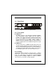
2.2 Front Panel FNSW-1600S Figure 1: Front View of the FNSW-16/2400S 2.2.1 Ports Speed n 100Base-TX All 100Base-TX ports come with auto-negotiation capability. They automatically support 100Base-TX and 10Base-T networks. Users only need to plug a working network device into one of the 100Base-TX ports, then turn on the hub. The port will automatically runs in 10Mbps, 20Mbps, 100Mbps or 200Mbps after the negotiation with the connected device. Port speed adjustment is also available through console port.
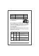
Port Type Cable Type Connector 10Base-T Cat 3, 4, 5 RJ-45 100Base-TX Cat.5 UTP only RJ-45 100Base-FX* 62.5/125µm multi-mode fiber ST / SC Table A: Supported port list 23 24 19 20 2.2.3 MDI Switch Reset Each numbered port of the Switch are MDI-X port, you can direct use straight cable for the connection to your end nodes. However, port 12/20 is with one push button. To push the button to convert the port to MDI-II port for direct hub cascade.
LOWER Steady Green ROW OFF 100M 10M Lit to indicate that a valid physical UTP/STP connection exists on that port runs in 100Mbps Remains off and Link ON to indicate the port runs in 10Mbps Table B: FNSW-2400S Port-LED Functions 2.3 The Rear Panel Figure 2: Rear View of the Switch 2.3.1 Extension Slot The Switch port 16/24 can be a 100Base-FX switching port as the extension module installed. As the module installed, the port 16/24 on the front panel will be disabled.
2.3.4 RS-232 Console The RS-232 console helps to manage the Switch. Please use the cable with the package. Attach one end to the switch and the other to your PC’s COM1 or COM2. Then startup your console program like Windows Hyper Terminal, or ProCOMM with parameter: 19200, n, 8, 1. Please refer to Chapter 4, Console management for more.
This page intentionally left blank! 12 PLANET NOVASwitch series
3. INSTALLATION The Switch do NOT require software configuration. Users can immediately use any of the features of this product simply by attaching the cables and turning on the power. However, the Console port will helps to have more setting to your Switch. To get the best use of the Switch, many things need to be considered first. See Chapter 5 for details. 3.1 Rack-Mount Installation Most users prefer to attach the power cord to the hub before installation in a network rack.
3.3 Power notes: 1. The device is a power-required device, it means, it will not work till it is powered. If your networks should active all the time, please consider use an UPS (Uninterrupted Power Supply) for your device. It will prevent you from network data loss or network downtime. 2. In some area, installing a surge suppression device may also help to protect your hub from being damaged by unregulated surge or current to the Switch or the power adapter.
4.CONSOLE CONFIGURATION On the rear panel, there is one console port for configuring the switch. The attached cable in the packing box is used to connect to PC’s RS232C port (COM1, or COM2). Following the instructions below to configure the switch. 4.1 CONNECT TO PC RS-232 serial cable Attach the RS-232 cable 9-pin female connector to the male connector on the demo board. Plug the other side of this cable to your PC.
There are six options available for the console setup: (1) Trunk / VLAN Setting (2) Port Status (3) Port Setting (4) Factory Setting (5) Redundant Link (6) Save Setting To enter any of the sub-menu, simply follow the instruction and type the number on the command line, and press ENTER. 4.2 Trunk/ VLAN Setting Entry: Select “1” from (1) Trunking (2) VLAN Setting (3) Exit >> Purpose: Set up the TRUNKING or VLAN Group Be noted: the Switch support either TRUNKING or VLAN.
Default: No Trunk Group in the device.
Purpose: Set up the VLAN Group Default: No VLAN Group in the device (all ports in VLAN1) Note: Use Toggle to select VLAN group and “SAVE” to make the setting take effect. VLAN setting example 1, Follow the selection to add port 1 to VLAN2.
VLAN3 VLAN4 X X X X 4.3 Port Status Entry: Select “2” from < Console Manu> PORT AutoN BackP Pause 01 02 03 04 05 06 07 08 09 10 11 12 13 14 15 16 17 18 19 20 21 22 23 24 X X X X X X X X X X X X X X X X X X X X X X X X X X X X X X X X X X X X X X X X X X X X X X X X X X X X X X X X X X X X X X X X X X X X X X SWITCH in 1-VLAN mode Any key to quit!! Purpose: Display the Port Status group AutoN for “Auto-Negotiaion”, BackP for “Back Pressure”, half-duplex flow control.
Enable port 2’s PAUSE frame support Enetr Port Number ((qq) to quit)>> 2 Select (1)Port Mode (2)Pause (3)Back Pressure>>2 Select Pause in FDX (1)Enable (2)Disable>>1 PAUSE frame is used while the devices that connect to the Switch runs in Full-duple mode. In full-duplex mode, once the Switch can not handle the incoming packets, the Switch send out the PAUSE frame to warn the device hold the transmission.
Set up the Factory default value, the system will be Auto Reboot 4.6 Redundant Link Setting Entry: Select “5” from < Console Manu> Redundant Link on Port-20/Port-19(19 is Backup link) (1)Enable (2)Disable >>1 Purpose: Set up Redundant Link. So the backup line enabled once the primary line is absent. 4.7 Save Setting Entry: Select “6” from < Console Manu> Purpose: Set up the Save Setting, save the setting to EEPROM.
This page intentionally left blank! 22 PLANET NOVASwitch series
5.OPTIMIZING CONFIGURATION 5.1 Prior to Installation Before installing the Switch and connecting network devices, it is important to plan the new network layout. Consider: • Dedicated Bandwidth: File servers and other high-traffic • • • • hardware can improve if they have their own direct connection with dedicated 10 or 100Mbps bandwidth. Full-Duplex: Determine which devices would benefit from a Full Duplex connection and check that they support it.
5.3 Fast Ethernet 100Base-TX and 100Base-FX are called "Fast Ethernet." This is because they use the Ethernet CSMA/CD access rules and data packet structure, but data travels ten times faster (100Mbps) than traditional 10Mbps Ethernet. Below is a list of the cable types and connectors that supported by Switch for 10Base-T, 100Base-TX, and 100Base-FX networks. PORT TYPE 100BASE-TX 10BASE-T CABLES TYPE Cat. 5 UTP only Cat.
5.4 Auto-Negotiation The 100Base-TX ports on the Switch have built-in "AutoNegotiation". This technology automatically sets the best possible bandwidth when a connection is established with another network device (usually at Power On or Reset). This is done by detect the mode and speed at the second device is capable of. The 100Base-TX devices can connect with the 100Base-TX port in either Half- or Full-Duplex mode.
5.6 Sample Application The optimal application for the Switch, no matter with the extension module or not, is as a "big pipe" backbone interconnecting file servers with bandwidth-hungry workgroups, departments, and offices. In the figure, the first FNSW-2400S links to another switch‘s Uplink (MDI-II) port, some ports connect to 100Mbps Workstations, and attached to file servers at 200Mbps.
6.TROUBLESHOOTING SYMPTOM CHECKPOINT SYMPTOM CHECKPOINT SYMPTOM CHECKPOINT Link LED does not lit after cable is connected to the port. 4 Verify that the other end of the cable is connected to a device that is powered on and on-line. 4 For UTP cable connection to another hub, verify that only one end of the cable is connected to a “MDI-II” Uplink port. 100Base-TX port Link LED is lit, Collision LED is blinking, but traffic is irregular.
This page intentionally left blank! 28 PLANET NOVASwitch series
7.PRODUCT SPECIFICATIONS PRODUCT FNSW-1600S / FNSW-2400S NETWORK PORTS 16/24 10/100Base-TX RJ-45 (MDI-X) BUFFER MEMORY 4Mb EXTENSION SLOT 1 open slot (shared with port 16/24 for optional module) MEDIA SUPPORT 100Base-TX Cat. 5 UTP, RJ-45 10Base-T Cat. 3, 4, 5 UTP RJ-45 100Base-TX, 200/100/20/10Mbps, Auto-Negotiation BANDWIDTH FILTER/ FORWARD RATE MAC ADDRESSES SWITCHES 148,800 packets/second per port @ 100Mbps, max. 14,880 packets/second per port @ 10Mbps, max.
8. RJ-45 PIN ASSIGNMENT 1 Numbered Ports (MDI-X port) Input Receive Data + 2 Input Receive Data - 3 Output Transmit Data+ Input Receive Data + 6 Output Transmit Data- Pin 4,5,7,8 Not used Uplink Port (MDI-II port) Output Transmit Data+ Output Transmit Data- Input Receive Data Not used Schematics for both straight and crossover twisted-pair cable are shown below. (Note that crossover cable is only required if you cascade hubs via the RJ-45 station ports; i.e. the Uplink port is not used.) 8.
EMFNSWSv1 ISO9002