48-Port 10/100Mbps Fast Ethernet Switch FNSW-4800v2 User's Manual
Trademarks Copyright © PLANET Technology Corp. 2008. Contents subject to revision without prior notice. PLANET is a registered trademark of PLANET Technology Corp. All other trademarks belong to their respective owners. Disclaimer PLANET Technology does not warrant that the hardware will work properly in all environments and applications, and makes no warranty and representation, either implied or expressed, with respect to the quality, performance, merchantability, or fitness for a particular purpose.
communications. Operation of this equipment in a residential area is likely to cause harmful interference in which case the user will be required to correct the interference at his own expense. CE Mark Warning This is a Class A product. In a domestic environment, this product may cause radio interference, in which case the user may be required to take adequate measures.
Table Of Contents 1. Introduction............................................................................... 5 1.1 Checklist.............................................................................. 5 1.2 About the Switch.................................................................. 5 1.3 Features.............................................................................. 6 1.4 Specification......................................................................... 7 2. Hardware Description.....
1. Introduction 1.1 Checklist Check the contents of your package for following parts: ● FNSW-4800 x 1 ● User’s manual x 1 ● Power cord x 1 ● Rubber feet x 4 ● Two rack-mounting brackets with attachment screws x 1 If any of these pieces are missing or damaged, please contact your dealer immediately, if possible, retain the carton including the original packing material, and use them against to repack the product in case there is a need to return it to us for repair.
the switch operation status and troubleshooting. These LED indicators display the power status for the system, LNK/ACT for each 10/100Mbps port. 1.3 Features ● Comply with IEEE 802.3 and IEEE 802.3u standards for 10/100BaseTX ● 48-Port 10/100Mbps Fast Ethernet Switch ● Each Switching ports support auto-negotiation-10/20, 100/200Mbps supported ● Auto-MDI/MDI-X detection on each RJ-45 port ● Prevents packet loss with back pressure (Half-duplex) and 802.
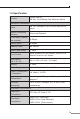
1.4 Specification Product FNSW-4800v2 48-Port 10/100Mbps Fast Ethernet Switch Hardware Specification Ports 48 10/ 100Base-TX RJ-45 Auto-MDI/MDI-X ports Switch Processing Scheme Store-and-Forward Throughput (packet per second) 6.6Mpps Switch fabric 8.8Gbps Address Table 8K entries Share data Buffer 2.5Mbit Flow Control Back pressure for half duplex, IEEE 802.3x Pause Frame for full duplex Dimensions (W x D x H) 440 x 260 x 44 mm, 1U height Weight 3.
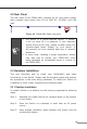
2. Hardware Description This product provides two different running speeds – 10Mbps, 100Mbps in the same Switch and automatically distinguishes the speed of incoming connection. This section describes the hardware features of FNSW-4800. For easier management and control of the Switch, familiarize yourself with its display indicators, and ports. Front panel illustrations in this chapter display the unit LED indicators. Before connecting any network device to the FNSW-4800, read this chapter carefully. 2.
2.2 Rear Panel The rear panel of the FNSW-4800 indicates an AC inlet power socket, which accepts input power from 100 to 240V AC, 50-60Hz, and 0.6A max. Figure 2-2 FNSW-4800 Switch rear panel Note 1. The device is a power-required device, it means, it will not work till it is powered. If your networks should active all the time, please consider using UPS (Uninterrupted Power Supply) for your device. It will prevent you from network data loss or network downtime. 2.
Note Step 4: When choosing a location, please keep in mind the environmental restrictions discussed in Chapter 1, Section 4, Specification. Connect your Switch to network devices. A. Connect one end of a standard network cable to the 10/100 RJ-45 ports on the front of the FNSW-4800 Switch. B. Connect the other end of the cable to the network devices such as printer servers, workstations or routers…etc. Note Step 5: Connection to the Switch requires UTP Category 5 network cabling with RJ-45 tips.
Figure 2-3 Attaching the brackets to the Switch Caution You must use the screws supplied with the mounting brackets. Damage caused to the parts by using incorrect screws would invalidate your warranty. Step 3: Secure the brackets tightly. Step 4: Follow the same steps to attach the second bracket to the opposite side. Step 5: After the brackets are attached to the Switch, use suitable screws to securely attach the brackets to the rack, as shown in Figure 2-4.
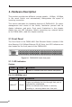
3. Switch Operation 3.1 Address Table The Switch is implemented with an address table. This address table composed of many entries. Each entry is used to store the address information of some node in network, including MAC address, port no, etc. This information comes from the learning process of Ethernet Switch. 3.2 Learning When one packet comes in from any port. The Switch will record the source address, port no. And the other related information in address table.
network needs efficiency and stability. The Ethernet Switch scans the destination address from the packetheader, searches the routing table provided for the incoming port and forwards the packet, only if required. The fast forwarding makes the switch attractive for connecting servers directly to the network, thereby increasing throughput and availability. However, the switch is most commonly used to segment existing hubs, which nearly always improves overall performance.
4.Troubleshooting This chapter contains information to help you solve issues. If the Switch is not functioning properly, make sure the Ethernet Switch was set up according to instructions in this manual. The Link/Act LED is not lit Check the cable connection of the Switch. Solution Performance is bad Solution Check the speed duplex mode of the partner device. The FNSW-4800 is run at Auto-negotiation mode and if the partner is set to half duplex, then the performance will be poor.
Appendix A Networking Connection A.1 Switch‘s RJ-45 Pin Assignments 10/100Mbps, 10/100Base-TX Contact MDI MDI-X 1 1 (TX +) 3 2 2 (TX -) 6 3 3 (RX +) 1 6 6 (RX -) 2 4, 5, 7, 8 Not used Not used A.2 RJ-45 cable pin assignment 6 32 1 6 321 6 3 21 There are 8 wires on a standard UTP/STP cable and each wire is colorcoded.
This page is intentionally left blank