Wired / Wireless Internet Fiber Router FRT-401 / 401S15 / 405 FRT-401N / 401NS15 / 405 User's Manual 1
Copyright Copyright© 2010 by PLANET Technology Corp. All rights reserved. No part of this publication may be reproduced, transmitted, transcribed, stored in a retrieval system, or translated into any language or computer language, in any form or by any means, electronic, mechanical, magnetic, optical, chemical, manual or otherwise, without the prior written permission of PLANET.
CE mark Warning This is a class B device, in a domestic environment; this product may cause radio interference, in which case the user may be required to take adequate measures. Energy Saving Note of the Device This power required device does not support Stand by mode operation. For energy saving, please remove the DC-plug or push the hardware Power Switch to OFF position to disconnect the device from the power circuit.
Table of Contents 1. INTRODUCTION ........................................................................................................................................................ 6 1.1 Feature ................................................................................................................................ 7 1.2 Package Contents .............................................................................................................. 7 1.3 Physical Details ........................
3.4.4 System Security Settings.......................................................................................................................... 49 3.4.5 Content Filtering ...................................................................................................................................... 50 3.5 Fiber / OAM Setting .......................................................................................................... 51 3.5.1 Fiber Configuration..................................
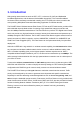
1. Introduction With growing network services such as HDTV, IPTV, voice-over-IP (VoIP) and Multimedia broadband applications, and the demand of bandwidth rises quickly. The current Broadband environment has not already accorded with needing; the FTTH (fiber-to-the-home) would be the most promising NGN (Next Generation Networking) application to fulfill the demand.
1.1 Feature 1. Fiber Interface support 2. Complies with IEEE 802.3, IEEE 802.3u 10/100Base-TX, 100Base-FX standard 3. Long distance connection based on optical fiber transceiver 4. Choice of fiber-connector from SC, MT-RJ / VF-45 and WDM, multi-mode / single-mode fiber / 100Base SFP 5. Co-work with PLANET 100Base-FX Media Conversion and MFB-Series Transceiver 6. QoS support 7. 802.1Q VLAN support 8. Supports FTTH / IPTV applications 9. Built-in 4-port 10/100 Mbps Ethernet switch 10.
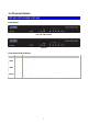
1.3 Physical Details FRT-401 / FRT-401S15 / FRT-405 Front Panel FRT-401 / FRT-401S15 FRT-405 Front Panel LED definition LED State Description ON When the router is powered on, and in ready state. OFF When the router is powered off. PWR Flashing Data is being transmitted or received via the fiber connection. WAN ON The optical fiber connection connected successfully. Flashing Data is being transmitted or received via the corresponding LAN port. LAN1-4 ON The port is up.
Front Panel FRT-401 / FRT-401S15 FRT-405 Rear Panel Port and Button Definition Connector Description POWER Power connector with 12V DC 1 A RESET Press more than 3 seconds for reset to factory default setting. LAN (1-4) WAN Router is successfully connected to a device through the corresponding port (1, 2, 3, or 4). If the LED light of LNK/ACT is flashing, the Router is actively sending or receiving data over that port.
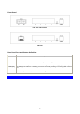
FRT-401N / FRT-401NS15 / FRT-405N Front Panel FRT-401N / FRT-401NS15 FRT-405N Front Panel LED definition LED State Description ON When the router is powered on, and in ready state. OFF When the router is powered off. ON WPS client registration is successful. PWR WPS WLAN Flashing WPS client registration window is currently open. OFF WPS is not available, or WPS is not enabled or initialized. ON WLAN radio is on. Flashing Data is being transmitted through WLAN. OFF WLAN radio is off.
Front Panel FRT-401N / FRT-401NS15 FRT-405N Rear Panel Port and Button Definition Connector Description POWER Power connector with 12V DC 1 A RESET Press more than 3 seconds for reset to factory default setting. LAN (1-4) Router is successfully connected to a device through the corresponding port (1, 2, 3, or 4). If the LED light of LNK/ACT is flashing, the Router is actively sending or receiving data over that port. WPS WPS on or off switch.
2. Installation This chapter offers information about installing your router. If you are not familiar with the hardware or software parameters presented here, please consult your service provider for the values needed. 2.1 System Requirement 1. Personal computer (PC) 2. Pentium III 266 MHz processor or higher 3. 128 MB RAM minimum 4. 20 MB of free disk space minimum 5. RJ45 Ethernet Port 2.
Connect the Fiber-optic cable to WAN port. Check the WAN LED on the front panel is on accordingly.
FRT-405 / FRT-405N 14
2.3 Configuring the Network Properties Configuring PC in Windows Vista 1. Go to Start / Control Panel / Network and Internet / Network and Sharing Center. Double-click on Network Connections. 2. Double-click Local Area Connection. 3. In the Local Area Connection Status window, click Properties.
4. Select Internet Protocol Version 4 (TCP/IPv4) and click Properties. 5. Select the Obtain an IP address automatically and the Obtain DNS server address automatically radio buttons. 6. Click OK to finish the configuration.
Configuring PC in Windows XP 1. Go to Start / Control Panel (in Classic View). In the Control Panel, double-click on Network Connections 2. Double-click Local Area Connection. 3. In the Local Area Connection Status window, click Properties.
4. Select Internet Protocol (TCP/IP) and click Properties. 5. Select the Obtain an IP address automatically and the Obtain DNS server address automatically radio buttons. 6. Click OK to finish the configuration.
Configuring PC in Windows 2000 2. Go to Start / Settings / Control Panel. In the Control Panel, double-click on Network and Dial-up Connections. Double-click Local Area Connection. 3. In the Local Area Connection Status window click Properties. 4. Select Internet Protocol (TCP/IP) and click Properties. 5. Select the Obtain an IP address automatically and the Obtain DNS server address automatically radio buttons. 6. Click OK to finish the configuration. 1.
Configuring PC in Windows 98/Me 1. Go to Start / Settings / Control Panel. In the Control Panel, double-click on Network and choose the Configuration tab. 2. Select TCP/IP Æ NE2000 Compatible, or the name of your Network Interface Card (NIC) in your PC. 3. Select the Obtain an IP address automatically radio button. 4. Then select the DNS Configuration tab. 5. Select the Disable DNS radio button and click OK to finish the configuration.
2.4 Configuring with Web Browser It is advisable to change the administrator password to safeguard the security of your network. To configure the router, open your browser, type “http: //192.168.1.1” into the address bar and click “Go” to get to the login page. Save this address in your Favorites for future reference. At the User name and Password prompt, type your proper user name and password to login. The default user name / password are “admin / admin”. You can change these later if you wish.
If the user name and password are correct, you will login Fiber Router successfully and see the status page. Now you can configure the Fiber Router for your needs.
3. Web Configuration Management Determine your connection settings Before you configure the router, you need to know the connection information supplied by your service provider. Connecting the Fiber Router to your network Unlike a simple hub or switch, the setup of the Fiber Router consists of more than simply plugging everything together.
3.1 Operation Mode The Fiber Router supports three operation modes – Router, Bridge and WISP (WISP mode is only supported for wireless fiber router). Currently, it comes pre-configured with Router mode. Note that, routing mode and bridging mode cannot be used simultaneously. For Bridge mode, all interfaces are bridged into a single bridge interface. For Router mode, the Fiber port is treated as WAN port. The other interfaces are bridged together and are treated as LAN ports.
3.2 Internet Settings 3.2.1 WAN The WAN Settings screen allows you to specify the type of Internet connection. The WAN settings offer the following selections for the router’s WAN port, STATIC (fixed IP), DHCP (Auto config), PPPoE, L2TP, and PPTP. ¾ STATIC (FIXED IP) Select STATIC (fixed IP) in the WAN Connection Type drop-down list and the following page appears.
Static Mode IP Address: Enter the IP address of WAN port. Subnet Mask: Enter IP subnet mask of WAN port. Default Gateway: Enter the default gateway address of WAN port. Primary DNS Server: Primary DNS Server f of WAN port. Secondary DNS Server: Secondary DNS Server of WAN port. MAC Clone MAC Clone provides WAN to connect to a MAC address. Enabled: Enable or disable MAC clone. After finishing setting, click Apply to save the settings and make the new configuration take effect.
¾ PPPOE Select PPPoE (ADSL) in the WAN Connection Type drop-down list and the following page appears. If the WAN connection type is set to PPPoE, you can configure the following parameters to PPPoE dial up. PPPoE Mode User Name: User name of PPPoE account Password: Password of PPPoE account Verify Password: Enter the password of PPPoE account again. Operation Mode: It provides two types of operation modes. Keep Alive means keeping on-line mode. You can set the redial period in the field.
¾ L2TP Select L2TP in the WAN Connection Type drop-down list and the following page appears. There are two address modes: Static and Dynamic. 1. If you select Static in the Address Mode field, the page shown in the following figure appears. 2. If you select Dynamic in the Address Mode field, the page shown in the following figure appears.
L2TP Mode Server IP: Address of L2TP server. User Name: The user name of L2TP account. Password: The password of L2TP account. IP Address: IP address of WAN port. Subnet Mask: Subnet mask of WAN port. Default Gateway: The default gate way of WAN port. Operation Mode: It provides two types of operation modes. Keep Alive means keeping on-line mode. You can set the redial period in the field. When the redial period expires, Router will execute dial-up again to keep online.
¾ PPTP Select PPTP in the WAN Connection Type drop-down list and the following page appears. There are two address modes: Static and Dynamic. PPTP Mode Server IP: Address of PPTP server. User Name: The user name of PPTP account. Password: The password of PPTP account. IP Address: IP address of WAN port. Subnet Mask: Subnet mask of WAN port. Default Gateway: The default gate way of WAN port. Operation Mode: It provides two types of operation modes. Keep Alive means keeping on-line mode.
3.2.2 LAN This page allows you may enable or disable networking functions and configure their parameters according to your practice. IP Address: Enter the IP address of LAN port. Subnet mask: Enter the subnet mask of LAN port. LAN2: The second IP switch of LAN port. You can enable or disable this function. LAN2 IP Address: The second IP address of LAN port. LAN2 Subnet Mask: The second IP Subnet Mask of LAN port. MAC Address: MAC address of LAN port (Read-only). DHCP Type: You can select Server or Disable.
Primary DNS Server: The primary DNS server address. Secondary DNS Server: The secondary DNS Server address. Default Gateway: The default gateway that DHCP server assigns. Lease Time: Lease time of the IP address. Statically Assigned: Assign IP to the assigned MAC address. Enter the assigned MAC address and IP in the corresponding fields. 802.1d Spanning Tree: Spanning Tree Protocol. You can select Enable or Disable. IGMP Proxy: You can select Enable or Disable. UPNP: Universal Plug and Play (UPNP).
3.2.4 Advanced Routing You can add or delete routing rules, enable or disable dynamic routing protocol in the page. Add a routing rule Destination: Enter the legal destination IP address. Range: Destination IP address is a host address or the network address. Gateway: Enter the specific gateway. Interface: The interface for this route. You can select LAN, WAN and Custom. Comment: Add the description of this route. After finishing the setting above, click Apply to make the new routing rule take effect.
3.2.5 QoS You may set up rules to provide Quality of Service (QoS) guarantee for some specific applications. In the page, you can enable or disable Quality of Service. After enabling QoS, you can set upload bandwidth and download bandwidth. Upload Bandwidth: You can select the proper bandwidth in the drop-down list. The value is from 64K to 60M. You can also set the bandwidth by selecting User defined and enter the proper bandwidth in the field.
3.3 Wireless Setting (For FRT-401N / 401NS15 / 405N) 3.3.1 Basic You can configure the minimum number of wireless settings for communication, such as network name (SSID) and channel. Wireless Network Radio On/Off: Enable or disable the wireless LAN. Network Mode: There are 6 modes: 11b only, 11g only, 11n only, 11b/g mixed, and 11b/g/n mixed mode. Network Name (SSID): The service set identification (SSID) is a unique name to identify the router in the wireless LAN.
Frequency (Channel): A channel is the radio frequency used by wireless device. Channels available depend on your geographical area. You may have a choice of channels (for your region) and you should use a different channel from an adjacent AP to reduce the interference. The Interference and degrading performance occurs when radio signals from different APs overlap. HT Physical Mode HT Physical Mode Operation Mode: Select Mixed Mode or Green Field. Channel Bandwidth: Select 20 or 20/40.
3.3.2 Advanced This page makes more detailed settings for the AP. Advanced Wireless Settings page includes items that are not available in the Basic Wireless Settings page, such as basic data rates, beacon interval, and data beacon rate. Advanced Wireless BG Protection Mode: It provides 3 options, including Auto, On, and Off. The default BG protection mode is Auto. Beacon Interval: The interval time range is between 20ms and 999ms for each beacon transmission. The default value is 100ms.
Short Slot: Select Disable or Enable. Tx Burst: Select Disable or Enable. Pkt_Aggregate: Select Disable or Enable. Country Code: Select the region which area you are. It provides six regions in the drop-down list. Wi-Fi Multimedia WMM Capable: Enable or disable WMM. APSD Capable: Enable or disable APSD. WMM Parameter: Click WMM Configuration button to pop up WMM Parameters of Access Point page. You can configure WMM parameters in the page.
3.3.3 Security Choose Wireless Settings>Security and the following page appears. It allows you to modify the settings to prevent the unauthorized accesses. Select SSID SSID choice: Select SSID in the drop-down list. Security Security Mode: There are 11 options, including Disable, OPEN, SHARED, WEPAUTO, WPA, WPA-PSK, WPA2, WPA2-PSK, WPAPSKWPA2PSK, WPA1WPA2, and 802.1X. [EXAMPLE] Take 802.1x for example. Select 802.1x in the Security Mode down-list. The page shown in the following page appears.
WEP: Disable or enable WEP. Radius Server IP Address: Enter the IP address of Radius Server. Port: The default port of the RADIUS server for authentication is 1812. You need not change this value unless your network administrator instructs you to do so with additional information. Shared Secret: Enter a password as the key to be shared between the external authentication server and the access point. The key is not send over the network.
3.3.4 WDS Wireless Distribution System (WDS) WDS Mode: There are four options, including Disable, Lazy Mode, Bridge Mode, and Repeater Mode. ¾ Disable Select Disable to disable the WDS mode. ¾ Lazy Mode WDS Mode: Select Lazy Mode. The FRT-40xN WDS Lazy mode is allowed the other FRT-40xN WDS bridge / repeater mode link automatically. Phy Mode: It provides 4 options, including CCK, OFDM, HTMIX, and GREENFIELD. Encryp Type: It provides 4 options, including None, WEP, TKIP, and AES.
WDS (Wireless Distribution System) allows access points to communicate with one another wirelessly in a standardized way. It can also simplify the network infrastructure by reducing the amount of cabling required. Basically the access points will act as a client and an access point at the same time. WDS is incompatible with WPA. Both features cannot be used at the same time.
3.3.5 WPS You can enable or disable the WPS function in this page. Select Enable in the WPS drop-down list. Click Apply and the following page appear. WPS Summary It displays the WPS information, such as WPS Current Status, WPS Configured, and WPS SSID. Reset OOB: Reset to out of box (OoB) configuration WPS Progress WPS mode: There are two way for you to enable WPS function: PIN, PBC. You can use a push button configuration (PBC) on the Wi-Fi router. If there is no button, enter a 4- or 8-digit PIN code.
3.3.6 Station List Through this page, you can easily identify the connected wireless stations. It automatically observes the ID of connected wireless station (if specified), MAC address, SSID, and current status.
3.4 Firewall The Fiber Router provides the fully firewall functions, such as IP/Port/MAC Filtering, Port Forwarding, DMZ, SPI Firewall and Content Filtering. It serves as an Internet firewall to protect your network from being accessed by outside users. 3.4.1 MAC/IP/Port Filtering Use the MAC/IP/Port filters to deny / allow particular LAN IP addresses from accessing the Internet. You can deny / allow specific port numbers or all ports for a specific IP address.
Basic Settings MAC/IP/Port Filtering: Enable or disable the MAC/IP/Port filtering function. Default Policy: The Packet that does not match any rules would be dropped or accepted. MAC/IP/Port Filter Settings MAC Address: Enter the MAC address that matches the source address of the packet (optional). Dest IP Address: Enter the IP address that matches the destination address of the packet (optional). Source IP Address: Enter the IP address that matches the source address of the packet (optional).
3.4.2 Port Forwarding (Virtual Server) The Virtual Server is the server or server(s) behind NAT (on the LAN), for example, Web server or FTP server, that you can make visible to the outside world even though NAT makes your whole inside network appear as a single machine to the outside world. This page allows you to set virtual server to provide services on the Internet. Virtual Server Settings Virtual Server Settings: Enable or disable this function.
3.4.3 DMZ DMZ (Demilitarized Zone) allows a single computer on your LAN to expose ALL of its ports to the Internet. Enter the IP address of that computer as a DMZ (Demilitarized Zone) host with unrestricted Internet access. When doing this, the DMZ host is no longer behind the firewall. This page allows you to set a De-militarized Zone (DMZ) to separate internal network and Internet. DMZ Settings: Enable or disable this function. After selecting Enable, you can set the DMZ IP address.
3.4.4 System Security Settings Choose Firewall > System Security and the following page appears. This page allows you to configure the system firewall to protect Router from attacking. Remote Management Remote management (via WAN): Deny or allow remote management through web. Remote management Port: The default remote management port is 80, you can change the remote management port for your needs. Ex. 8080.
3.4.5 Content Filtering This page is used to configure the Blocked URL (Such as tw.yahoo.com) and filtered keyword. Here you can add / delete URL and filtered keyword. Choose Firewall > Content Filtering and the following page appears. You can set content filter to restrict the improper content access. Webs Content Filters: If you want to block some applications as Proxy, Java and ActiveX of web pages please select the check box and click “Apply”.
3.5 Fiber / OAM Setting 3.5.1 Fiber Configuration This function allows displaying the Fiber port’s status, Mode, Flow Control and Rate limit. The Link Status in the screen displays the current connection speed and duplex mode. • Flow Control • Ingress Rate Limit • Egress Shaping Allow Enable or Disable flow control for selected port. • Enable – 802.
3.5.2 Remote Configuration The Remote TS-1000 Configuration is an advanced remote device monitor feature that allows you to Remote monitor and automatic notify status indication. Remote TS-1000 OAM Information The Fiber Router supports the TS-1000 and 802.3ah OAM, you can check the status and information of remote device by OAM. Click the “Get” to gat the OAM information from remote devices. It will show the IP, MAC and Port status.
2. Reset: Click the “Reset” button to reboot the remote device. 3. Factory: Click the “Factory” button to restore the default settings of remote device. Remote Port Configuration The users can manage the remote port from local Fiber Router; you can setup the Port Mode, Flow Control, Rate Limit for remote device.
3.5.3 OAM Configuration 802.3ah OAM Configuration When enable 802.3ah OAM function, all 802.3ah OAMPDU packets will trap to embedded CPU. Software will implement auto discovery procedure. With hardware support, software controls the 802.3ah remote loop back procedure. Hardware can also detect dying gasp even and interrupt CPU to send dying gasp even notification OAMPDU. All other functions defined by 802.3ah are implemented using embedded CPU.
Local TS-1000 OAM Configuration Local TS-1000 OAM Setup This function provides Local TS-1000 OAM Setup of Managed Media Converter. Press the “Apply” button to save the current configuration of Managed Media Converter. The below screen and Table describes the Local TS-1000 OAM Setup object of Managed Media Converter.
3.5.4 Loop back test 802.3ah Loop Back Test The 802.3ah Loop Back Test allows manual run this loop back test to check the interconnection between two devices. To assure the Remote 802.3ah function can work correctly. This function provides 802.3ah Loop Back Test of Fiber devices. Press the “Apply” button to run 802.3ah Loop Back Test and see the 802.3ah Loop Back Test Result of Fiber devices. The below screen and Table describes the 802.3ah Loop Back Test object of Fiber Router. Figure 802.
The 802.3ah Loop Back Test Web page includes the following configurable data: 802.3ah Loop Back Test Send Packet Number Allow input the number for packet send and the available options is 1 to 255. Default is 16. Packet Length (Not include CRC) Allow input the number for Packet Length and the available Apply button Press this button for save current configuration of Fiber Router. options is 60 to 1514. Default is 60. 802.3ah Loop Back Test Result Result Display the 802.3ah Loop Back Test Result.
In-band and out-band Loop back This function provides TS-1000 Loop Back Test of Fiber devices. Press the “Apply” button to run Loop Back Test and see the TS-1000 Loop Back Test Result of Fiber Route. The below screen and Table describes the TS-1000 Loop Back Test object of Managed Media Converter.
3.6 Administration You can configure admin management in this part. It includes Management, Update Firmware, Setting management, Reboot, Status, Statistics and System Log. 3.6.1 Management Choose Administration > Management, and the following page appears. You may configure administrator account and password, NTP settings, and dynamic DNS settings in the page. Administrator Settings Account: Enter the username of the administrator in the field.
Time Zone: Select the proper time zone in the drop-down list. NTP Server: Enter the IP address or domain name of NTP server. NTP Synchronization (hours): Enter the time interval for synchronization. DDNS Settings Dynamic DNS Provider: Select the proper dynamic DNS provider in the drop-down list. After selecting a dynamic DNS provider, you are allowed to set the following parameters. Account: Enter the username of DDNS provider in the field. Password: Enter the password of DDNS provider in the field.
3.6.3 Setting Management Choose Administration > Settings Management and the following page appears. You may save system settings by exporting them to a configuration file, restore them by importing the file, or reset them to the factory default. Export Settings Export Button: Click the Export to export the settings. Import Settings Settings file location: Click Browse to select the configuration file, and then click Import to upload the configuration file. Click Cancel to cancel the uploading operation.
3.6.4 Reboot The Reboot screen allows you to restart your router with its current settings. Click the “Reboot” button and the device will restart. 3.6.5 Status Choose Administration > Status and the following page appears. It displays the information about Router status, including system information, Internet configurations, and local network.
3.6.6 Statistics You can see the Statistic information in this screen. It includes the Traffic for all interfaces.
3.6.7 System Log The system log dialog allows you to view the system log and click the “Refresh” button to fresh the system event logs. Choose Administration > System Log and the following page appears. You are allowed to view and disable / enable the system log in this page. Click Refresh to refresh the log. Click Clear to clear the log.
Appendix A A.1 Device‘s RJ-45 Pin Assignments ■ 10/100Mbps, 10/100Base-TX Contact MDI MDI-X 1 1 (TX +) 3 2 2 (TX -) 6 3 3 (RX +) 1 6 6 (RX -) 2 4, 5, 7, 8 Not used Not used Implicit implementation of the crossover function within a twisted-pair cable, or at a wiring panel, while not expressly forbidden, is beyond the scope of this standard. A.2 RJ-45 cable pin assignment 6 32 1 6 321 6 3 21 There are 8 wires on a standard UTP/STP cable and each wire is color-coded.
A.3 Fiber Optical Cable Connection Parameter The wiring details are as below: ■ Fiber Optical patch Cables: Standard Fiber Type Cable Specification 100Base-FX Multi-mode 50/125μm or 62.5/125μm 100Base-FX Multi-mode 50/125μm or 62.5/125μm (1310nm) Single-mode 9/125μm 100Base-BX-U Single-mode 9/125μm (1300nm) (TX :1310/RX :1550) 100Base-BX-D (TX :1550/RX :1310) A.
Appendix B: Specification FRT-401 / FRT-401S15 / FRT-405 Product Model Ports Internet Fiber Router FRT-401 WAN 1 x 100Base-FX port LAN 4 x 10/100Base-TX port Connector Optic Interface FRT-401S15 SC Mode Single-mode Vary on module 2km 15km Vary on module 850nm 1310nm - Max. -14 -7 - Min. -19.0 -20 - -34.
FRT-401N / FRT-401NS15 / FRT-405N Product Model 802.11n Wireless Internet Fiber Router FRT-401N FRT-401NS15 Ports WAN 1 x 100Base-FX port LAN 4 x 10/100Base-TX port Wireless 1 x 802.11b/g/n Access Point, 2 x antennas detachable Connector Optic Interface SC Mode Single-mode Vary on module 2km 15km Vary on module 850nm 1310nm - Max. -14 -7 - Min. -19.0 -20 - -34.
Security Built-in NAT Firewall MAC / IP/ Port Filtering Content Filtering SPI Firewall support Password protection for system management Management Web-based configuration Available Syslog support TR-069* SNMP v1/v2c TS-1000 and 802.3ah OAM support * Feature Enhance by Future FW upgradeable.
Appendix C: Glossary Address mask A bit mask select bits from an Internet address for subnet addressing. The mask is 32 bits long and selects the network portion of the Internet address and one or more bits of the local portion. Sometimes it called subnet mask. VDSL2 VDSL2 (Very High-Bit-Rate Digital Subscriber Line 2), G.993.2 is the newest and most advanced standard of xDSL broadband wire line communications.
CO Central Office. Refers to equipment located at a Telco or service provider's office. CPE Customer Premises Equipment located in a user's premises DHCP (Dynamic Host Configuration Protocol) DHCP is software that automatically assigns IP addresses to client stations logging onto a TCP/IP network. DHCP eliminates having to manually assign permanent IP addresses to every device on your network. DHCP software typically runs in servers and is also found in network devices such as Routers.
FTP File Transfer Protocol. The Internet protocol (and program) transfer files between hosts. Hop count A measure of distance between two points on the Internet. It is equivalent to the number of gateways that separate the source and destination. HTML Hypertext Markup Language - The page-coding language for the World Wide Web. HTML browser A browser used to traverse the Internet, such as Netscape or Microsoft Internet Explorer.
MAC Media Access Control Layer - A sub-layer of the Data Link Layer (Layer 2) of the ISO OSI Model responsible for media control. MIB Management Information Base - A collection of objects can be accessed via a network management protocol, such as SNMP and CMIP (Common Management Information Protocol). NAT Network Address Translation - A proposal for IP address reuse, where the local IP address is mapped to a globally unique address.
RFC Request for Comments - Refers to documents published by the Internet Engineering Task Force (IETF) proposing standard protocols and procedures for the Internet. RFC can be found at www.ietf.org. Route The path that network traffic takes from its source to its destination. The route a datagram may follow can include many gateways and many physical networks. In the Internet, each datagram is routed separately.
one bridge as the 'root' bridge, with the highest priority one as identifier, from which all paths should radiate. Spoofing A method of fooling network end stations into believing that keep alive signals have come from and returned to the host. Polls are received and returned locally at either end Static IP Address A static IP address is an IP address permanently assigned to computer in a TCP/IP network.
UDP User Datagram Protocol - A connectionless transport protocol that runs on top of TCP/IP's IP. UDP, like TCP, uses IP for delivery; however, unlike TCP, UDP provides for exchange of datagram without acknowledgments or guaranteed delivery. Best suited for small, independent requests, such as requesting a MIB value from an SNMP agent, in which first setting up a connection would take more time than sending the data. UNI signaling User Network Interface signaling for ATM communications.