Trademarks Copyright PLANET Technology Corp. 2004 PLANET is a registered trademark of PLANET Technology Corp. All other trademarks belong to their respective owners. Contents in this document are subject to revision without prior notice. FCC Class A Appliance This equipment generates and uses radio frequency energy. If it is not installed and used properly in strict accordance with the manufacturer‘s instructions, it may cause interference to radio and television reception.
Table of Contents Chapter 1 General Introduction 1 1.1 Checklist 1 1.2 Introduction 1 1.3 Features 2 Chapter 2 Hardware Description 3 2.1 Front Panel 3 2.1.1 FSD-800/FSD-801 3 2.1.2 FSD-1600/FSD-1601 4 2.2 Rear Panel 5 2.3 Hardware Installation 7 Chapter 3 Configuration and Application 8 3.1 The Switch Operation 8 3.2 The Smart Function (16-port model) 9 3.2.1 TP or Fiber-optic selection (for FSD-1601 only) 9 3.2.2 Port-based VLAN 10 3.2.3 Port-Trunking 10 3.2.
Chapter 1 General Introduction 1.1 Checklist Check the contents of your package for following parts: • The Fast Ethernet Switch • User’s Manual • Power Cord If any of these pieces are missing or damaged, please contact your dealer immediately, if possible, retain the carton including the original packing material, and use them against to repack the product in case there is a need to return it to us for repair. 1.
1.3 Features • 8/16-port 10/100base-TX Auto-Negotiation Ethernet Switches • One optional 100Base-FX fiber port for extending up to 2km • Complies with the IEEE802.3 Ethernet and IEEE802.
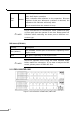
Chapter 2 Hardware Description This section describes the hardware features of the Switch. For easier management and control of the Switch, familiarize yourself with its display indicators, and ports. Front panel illustrations in this chapter display the unit LED indicators. Before connecting any network device to the hub, read this chapter carefully. 2.1 Front Panel The unit front panel provides a simple interface monitoring the Switch. It includes a power indicator for each port. 2.1.
Lit: Full duplex operation Unlit: Half duplex operation FDX/ Blink: indicates data collisions on the respective Ethernet Amber COL segment of this port. Whenever a collision is detected, the respective COL indicator will briefly blink. This is normal when the network is busy. Port # 8 of FSD-801 is a shared port. Either Twisted Pair port NOTE: or Fiber-optic port can operate in one time. Please power off FSD-801 before switching the share port to different connection type.
LED indicators Printing Power (PWR) Color Green Description This indicator lights green when the Switch is receiving power; otherwise, it is off. This indicator green when the port is connected to a either 10Mbps Ethernet or 100Mbs Fast Ethernet station , If the LNK/ ACT Green station to which the Switch is connected is powered off, or if there is a problem with the link, the LED will remain off. And the indicator blinking green when the data will be received to all other connected ports.
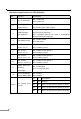
DIP Switch (Smart function for FSD-1600/1601) DIP 1 2 Function TP / FX Selection Description ON: Enable FX OFF: Enable TP Fiber Full/Half ON: Enable Fiber Full Duplex duplex Switch OFF: Enable Fiber Half Duplex ON: 3 15VLANs (port#1-15) with 1 overlapping VLAN topology port (port#16) topology type selection OFF: 14VLANs (port#1-14) with 2 overlapping port (port#15,16) topology 4 5 6 7 8 Port Based VLAN ON: Enable Trunk group 0 (port 1,2,3,4) OFF: Disable group 0 Port Trunk 1 ON: Enable Tr
1. For fiber-optic connection, please check the opposite end is using the same transmit mode before make the connection. 2. Port#16 of the switch is shared with 100Base-FX port. Make NOTE: sure either Fiber-optic or twisted pair port is being connected. 3. For more information about the Smart function, please refer to Chapter 3. 4. All the DIP is in OFF position by default! 2.3 Hardware Installation 1. Place the Switch on a smooth surface 2. Connect the output cord of power supply to the AC inlet. 3.
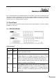
Chapter 3 Configuration and Application This chapter shows you how the Switch works, and how to install the Switch and also to configure the smart functions provided in the 16-port model. 3.1 The Switch Operation Address Table The Switch is implemented with an address table. This address table composed of many entries. Each entry is used to store the address information of some node in network, including MAC address, port no, etc. The information comes from the learning process of Ethernet Switch.
domain, reducing the overall load on the network. The Switch performs “Store-and-forward” therefore, no error packets occur. reliably, it reduces the re-transmission rate. No packet loss will occur. More Auto-Negotiation The STP ports on the Switch have built-in "Auto-Negotiation." This technology automatically sets the best possible bandwidth when a connection is established with another network device (usually at Power On or Reset).
3.2.2 Port-based VLAN Related DIP: 3, 4 Default meaning: No VLAN setting. VLAN can be used to separate ports into different groups in the same switch. This will secure port from being accessed by other ports on the switch. DIP 4: Turns on will enable the port-based VLAN capability DIP 3: The two positions represent two different VLAN choices: OFF:There are 14 VLANs. Port 1 to Port 14 can communicate with Port 15, and Port 16 where 1 to 14 cannot see each other. ON: There are 15 VLANs.
DIP 10: Turns on for VLAN tag priority QoS. The connected end-nodes (PCs, Routers) should also support NOTE: VLAN priority or ToS priority. Normally, these functions could turn off by default. Check the user’s guide of your networked device for this capability. 3.2.5 Port-based priority Related DIP: 11, 12 Default meaning: No hardware port priority.
Figure 3-1 10/100Mbps File server to Switch Connection 3.3.2 Connect to 100Base-FX Switch/Device (Model: FSD-801/1601) Plug the pair the fiber-cable to the Switch’s fiber-optic port, secure the fiber-optic connector. Connect to other end to the fiber-optic port of the device like repeater hub, switch or workstations. Be noted for the duplex mode. For Hub, only Half-Duplex mode can be selected, at the mean time, the cable distance cannot exceed 412 meters.
3.3.3 Set up the workgroup and uplink to the backbone (Model: FSD1600/1601) Figure 3-3 Connection with VLAN enable Turn on the DIP 4, the FSD-1600 soon separate the fourteen ports (Port 1 to Port 14) into different group, then you can install two file servers to port 15, port 16, those fourteen users shall not see each other where they can freely access the information from the two file server.
Chapter 4 Troubleshooting This chapter contains information to help you solve problems. If the Switch is not functioning properly, make sure the Switch was set up according to instructions in this manual. The Link LED is not Lit Solution: Make sure the switch configuration is consistent with the connecting device Check the cable connections. Performance is bad Solution: Check the full duplex status of the Ethernet Switch.
Appendix A Specifications General (Ethernet) IEEE 802.3 10Base-T EthernetIEEE 802.3u 100 Base-TX and Standards: 100Base-FX Fast EthernetIEEE 802.3x Flow control Protocol: CSMA/CD Ethernet: Data Transfer 10Mbps(half duplex) / 20Mbps (full duplex) Fast Ethernet: Rate: 100Mbps (half duplex) / 200Mbps (full duplex) Topology: Star General (Cabling) • 10Base-T:2-pair UTP Cat. 3,4, 5 (100 m, max.)EIA/TIA568 100-ohm STP (100 m, max.) • 100Base-TX:2-pair UTP Cat. 5 (100 m, max.
EMI FCC Class A, CE Mark Class A Performance Transmission Method Filtering Address Table Store-and-forward 1/8K entries Packet Filtering/ 14,880pps per port (for 10Mbps) Forwarding Rate 148,800pps per port (for 100Mbps) MAC Address Learning 16 Automatic update / Max age: fixed
Appendix B RJ-45 Pin Specification When connecting your FSD-series 10/100Mbps Ethernet Switch to another switch, a bridge or a hub, a modified crossover cable is not necessary. Each port of the Switch is auto-MDI detection. That means you can direct connect the Switch to any Ethernet devices with a Category 5, UTP straight wire.
This page is intentionally left blank 18
Part No.