5-Port 10/100Mbps Fast Ethernet Switch with 802.
Trademarks Copyright © PLANET Technology Corp. 2005. Contents subject to revision without prior notice. PLANET is a registered trademark of PLANET Technology Corp. All other trademarks belong to their respective owners. Disclaimer PLANET Technology does not warrant that the hardware will work properly in all environments and applications, and makes no warranty and representation, either implied or expressed, with respect to the quality, performance, merchantability, or fitness for a particular purpose.
Table of Contents Table of Contents............................................................................................................................. 3 ABOUT THIS GUIDE....................................................................................................................... 4 Chapter 1 INTRODUCTION ............................................................................................................ 5 Chapter 2 UNPACKING AND SETUP ..............................................
ABOUT THIS GUIDE Thank you for purchasing the FSD-504PE, 5-Port 10/100Mbps Fast Ethernet Switch with 802.3af splitter built-in. This device integrates 100Mbps Fast Ethernet and 10Mbps Ethernet network capabilities in a highly flexible desktop package and also offers dual power system, DC power and IEEE802.3af in-line power over Ethernet. Purpose This manual discusses how to install your FSD-504PE. 5-Port 10/100Mbps Fast Ethernet Switch w/802.3af splitter built-in.
Chapter 1 INTRODUCTION This chapter describes the features of the Switch and some background information about Fast Ethernet switching technology. Fast Ethernet Technology The growing importance of LANs and the increasing complexity of desktop computing applications are fueling the need for high performance networks. A number of high-speed LAN technologies have been proposed to provide greater bandwidth and improve client/server response times.
collision domains, making it possible to expand your Fast Ethernet network beyond the 205-meter network diameter limit for 100Base-TX networks. Switches supporting both traditional 10Mbps Ethernet and 100Mbps Fast Ethernet are also ideal for bridging between the existing 10Mbps networks and the new 100Mbps networks. Switching LAN technology is a marked improvement over the previous generation of network bridges, which were characterized by higher latencies.
10Mbps or 100Mbps workgroups. With the highest bandwidth 200Mbps (100Mbps full-duplex mode), any port can provide workstations with a congestion-free data pipe for simultaneous access to the server. The Switch is expandable by cascading two or more switches together. As all ports support 200Mbps, the Switch can be cascaded from any port and to any number of switches.
Chapter 2 UNPACKING AND SETUP This chapter provides unpacking and setup information for the Switch. Unpacking Open the shipping cartons of the Switch and carefully unpacks its contents. The carton should contain the following items: One 5-Port 10/100Mbps Ethernet Switch One External power adapter (optional, vary on model) This User’s manual If any item is found missing or damaged, please contact your local reseller for replacement.
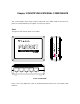
Chapter 3 IDENTIFYING EXTERNAL COMPONENTS This section identifies all the major external components of the Switch. Both the front and rear panels are shown followed by a description of each panel’s feature. Panel The figures below show the panels of the switch. Panels of FSD-504PE Please refer to the LED panel section for detailed information about each of the switch’s LED indicators.
DC Power Power is supplied through an external AC power adapter. Check the technical Jack: specification section for information about the AC power input voltage. Since the switch does not include a power switch, plugging its power adapter into a power outlet will immediately power it on. POE The Switch supports two power systems, 12VDC or powered from POE. Port # 1 supports 802.3af in-line power. Either power system can be deployed to the Switch at a time.
Chapter 4 CONNECTING THE SWITCH This chapter describes how to connect the Switch to your Fast Ethernet network. PC to Switch A PC can be connected to the Switch via a two-pair Category 3, 4, 5 UTP/STP straight cable. The PC (equipped with a RJ-45 10/100Mbps phone jack) should be connected to any of the 5 numbered port. The LED indicators for PC connection depend on the LAN card capabilities.
Powered from POE hub / switch Port#1 of the Switch support IEEE802.3af power over Ethernet, you can direct connect the Switch to the 802.3af in-line power devices like 802.3af POE hub, Ethernet Switches that with 802.3af POE Ethernet port. A Category 5 UTP cable with 4-pair wire is required from POE hub to your FSD-504PE. Once the Switch connect with POE device like PLANET POE-150, 1-Port 802.
will require four-pair Cat 5/5e UTP/STP cable. When using straight or crossover cable, this is done from the any (MDI/MDIX) port of the Switch (Switch A) to any of the 10Mbps or 100Mbps (MDI-X) port of the other switch (switch B) or other devices. The LNK/ACT, 100 LED indicators light green for hookup to 100Mbps speed or only LNK/ACT light green for hookup to 10Mbps speed.
Chapter 5 TECHNICAL SPECIFICATIONS Model FSD-504PE Standards IEEE802.3 10Base-T Ethernet IEEE802.3u 100Base-TX Fast Ethernet IEEE802.3af Power over Ethernet Protocol CSMA/CD Data Transfer Rate Ethernet: 10Mbps (half duplex), 20Mbps (full duplex); Fast Ethernet: 100Mbps (half duplex), 200Mbps (full duplex) Topology Star Network Cables EIA/TIA- 568 100-ohm STP (max. 100 m); 10BaseT: 2-pair UTP Cat. 3,4,5; 100Base-TX: 2-pair UTP Cat. 5; POE: 4-pair UTP Cat.
APPENDIX A RJ-45 PIN SPECIFICATION When connecting your FSD-series 10/100Mbps Ethernet Switch to another switch, a bridge or a hub, a straight or crossover cable is necessary. Each port of the Switch supports auto-MDI/MDI-X detection. That means you can directly connect the Switch to any Ethernet devices without making a crossover cable.
There are 8 wires on a standard UTP/STP cable and each wire is color-coded. The following shows the pin allocation and color of straight cable and crossover cable connection: Figure A-1: Straight-Through and Crossover Cable Please make sure your connected cable are with same pin assignment and color as above picture before deploying the cables into your network.
APPENDIX B SWITCH OPERATION Address Table The Switch is implemented with an address table. This address table composed of many entries. Each entry is used to store the address information of some node in network, including MAC address, port no, etc. The information comes from the learning process of Ethernet Switch. Learning When one packet comes in from any port, the Ethernet Switch will record the source address, port no. and the other related information in address table.
Due to the learning function of the Ethernet switch, the source address and corresponding port number of each incoming and outgoing packet are stored in a routing table. This information is subsequently used to filter packets whose destination address is on the same segment as the source address. This confines network traffic to its respective domain, reducing the overall load on the network. The Switch performs “Store-and-forward” therefore, no error packets occur.
Appendix C Troubleshooting 1. Power LED does not turns on? Ans: The Switch supports two power sources, 12VDC and 802.3af, please check which kind of power system deployed. a) Powered from POE: please check with network administrator if the POE injector device is complied with 802.3af standard and well connected to port#1 of the Switch with 4-pair UTP cable within 100 meters. FSD-504PE will detect the signal from 802.3af POE device and response to get the 48VDC power. Connect with non-802.