User's Manual FT-902 FT-902S15/S35/S50 FT-905A FT-906A20/906B20 10/100Base-TX to 100Base-FX Web Smart Media Converter
Trademarks Copyright © PLANET Technology Corp. 2007. Contents subject to which revision without prior notice. PLANET is a registered trademark of PLANET Technology Corp. All other trademarks belong to their respective owners.
TABLE OF CONTENTS 1. INTRODUCTION............................................................................................................................................................. 1 1.1 PACKAGE CONTENTS .................................................................................................................................................... 1 1.2 HOW TO USE THIS MANUAL ........................................................................................................................
1. INTRODUCTION 1.1 Package Contents Check the contents of your package for following parts: ● Web Smart Media Converter x1 ● CD-ROM user's manual x1 ● Quick installation guide x1 ● External 5VDC/2A power adapter x 1 If any of these are missing or damaged, please contact your dealer immediately, if possible, retain the carton including the original packing material, and use them against to repack the product in case there is a need to return it to us for repair.
; Supports Bandwidth Control (Kbps) for both Ingress and Egress ; Supports Broadcast Storm Control to optimize network bandwidth.
2. INSTALLATION This section describes the functionalities of FT-90X’s components and guides how to install it on the desktop or shelf. Basic knowledge of networking is assumed. Please read this chapter completely before continuing. 2.1 Product Description The Web-Smart FT-90x Media Converters supports conversion between 10/100Base-TX and 100Base-FX network. There are SC/SFP connectors and single-mode/multi-mode media for your needs.
2.1.1 FT-90X Front Panel Figure 2-1, 2-2 & 2-3 shows a front panel of FT-90X.
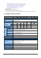
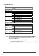
2.1.2 LED Indicators ■ ■ System LED Color PWR Green Function Lit: Power on. 10/100Base-TX Port LED Color Function Lit: LNK/ACT FDX 100 ■ Green Blink: Indicate that the converter is actively sending or receiving data over that port. Off: Indicate that the port is link down or no data flow. Lit: Indicate that the connection made through the corresponding port is running in Full-Duplex mode. Off: Indicate that the connection made through the corresponding port is running in Half-Duplex mode.
2.1.3 FT-90X Rear Panel The rear panel of the converter indicates one DC jack, which accepts input power with 5V DC 2A. ■ FT-90x series Figure 2-6 Rear Panel of FT-90x Power Notice: 1. The device is a power-required device, it means, it will not work till it is powered. If your networks should active all the time, please consider using UPS (Uninterrupted Power Supply) for your device. It will prevent you from network data loss or network downtime. 2.
2.2 Install the Converter This section describes how to install your FT-90X Web Smart Media Converter and make connections to the converter. Please read the following topics and perform the procedures in the order being presented. The hardware installation of PLANET FT-90X Web Smart Media Converter do not need software configuration. To install your FT-90X on a desktop or shelf, simply complete the following steps. 10/100Base-TX Cat.
#Note: Please refers to APPENDIX-A for detailed wiring information of the FT-90X. To prevent from optic acceptor malfunction, check the both wires / transmitter before power on the converter. FT-905A Installation FT-905A is with high reliability and flexibility to extend the distance up to 2Km, 20Km, or longer. It depends on the 100Base-FX SFP transceiver modules. The SFP transceivers are hot-plug e and hot-swappable.
2.2.2 Chassis Installation and Rack Mounting To install the media converter in a 10-inch or 19-inch with standard rack, follow the instructions described below. Step 1: Place your FT-90X on a hard flat surface, with the front panel positioned towards your front side. Step 2: Carefully slide in the module until it is fully and firmly fitted into the slot of the chassis.
Figure 2-2 Mounting the Chassis in a Rack -10-
3. WEB MANAGEMENT This chapter describes how to manage the FT-90X. Topics include: - Overview - Management methods - Assigning an IP address to the FT-90X - Logging on to the FT-90X 3.1 Overview This chapter gives an overview of converter management. The FT-90X provides a simply WEB browser interface.
3.2.2 Login the media converter Before you start configure the FT-90X, please note the FT-90X is configured through an Ethernet connection, make sure the manager PC must be set on same the IP subnet address. For example, the default IP address of the FT-90X is 192.168.0.100, then the manager PC should be set at 192.168.0.x (where x is a number between 2 and 254), and the default subnet mask is 255.255.255.0. Use Internet Explorer 6.0 or above Web browser. Enter IP address http://192.168.0.
4. CONFIGURATION The FT-90X Web Smart Media Converter provide Web interface for Media converter smart function configuration and make the Media converter operate more effectively - They can be configured through the Web Browser. A network administrator can manage and monitor the FT-90x from the local LAN. This section indicates how to configure the media converter to enable its smart function. 4.
4.2 System 4.2.1 System Information The System Information page provides information for the current device. System Info page helps a network manager to identify the versions and IP Address etc. The screen in Figure 4-2 appears. Figure 4-2 System Information screen The page includes the following fields: • MAC Address Specifies the device MAC address. • Software Version The current software version running on the device. • IP Address The current IP Address of the device.
4.2.2 IP Configuration The IP Configuration includes the IP Address, Subnet Mask and Gateway. The screen in Figure 4-3 appears. Figure 4-3 IP Configuration screen The page includes the following configurable data: IP Address - The IP address of the interface. The factory default value is 192.168.0.100 Subnet Mask - The IP subnet mask for the interface. The factory default value is 255.255.255.0 Gateway - The default gateway for the IP interface. The factory default value is 192.168.0.
4.2.3 Password Setting This function provides administrator to secure Web login. The screen in Figure 4-4 appears. Figure 4-4 Password Setting screen The page includes the following configurable data: Login Name Displays the user name. Old Password Enter the old password is required before entering the new password New Password Specifies the new password. The password is not displayed. As it entered an “y” corresponding to each character is displayed in the field.
4.3 Port Configuration This function allows displaying each port’s status. The Link Status in the screen displays the current connection speed and duplex mode; else this function will show down when the port is disconnected. Press the “Refresh” button to renew the screen. The screen in Figure 4-5 appears.
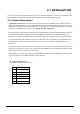
Default value: No Limit The Ingress Rate Limit configuration field as show in Figure 4-6. • Egress Shaping The value of outbound traffic limitation in kilobit-per-second (kbps). The possible values are : • No Limit • 512K • 1M • 2M • 4M • 8M • 10M • 50M Default value : No Limit The Egress Shaping configuration field as show in Figure 4-7. #Note: When set each port to run at 100M Full, 100M Half, 10M Full, and 10M Half-speed modes. The Auto-MDIX function will disable.
Figure 4-7 Port Configuration-Egress Shaping screen -19-
4.4 Converter Configuration This page allows setup Management Port, Loop Back Reply, Broadcast Storm Control, Class of Services and LLR Mode. Press the “Apply” button to take affect. The screen in Figure 4-8 appears. Figure 4-8 Converter Configuration screen The page includes the following fields: • Management Port Allow to filter the Web management packets for this converter by income port.
• First In First Out • Strict Priority • Weighted Round Robin • WRR Priority (High: Low) This field is available when choose Weighted Round Robin as Class of Service schedule. It indicates that traffic output ration of high priority and low priority. The possible field values are: • 1:1 • 2:1 • 4:1 • 8:1 • LLR Mode To enable or disable the LLR (Link Loss Return) function of the device.
When multiple CoS schemes are enabled, the data packet is treated as the high priority as long as any one of three CoS schemes is mapped to “high”. Take the following example for detail explanation. If a port is set as a low priority port, when it receives a packet, which embeds with high priority VLAN tag, this packet will be forwarded as a high priority packet. In the other words, the priority of a packet would be set to high if any of two CoS schemes is interpreted as the high priority.
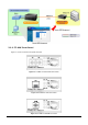
Management Switch/Hub Media Station Converter w/SNMP LLCF i d f Media Converter LLCF i d f lt Switch/Hub Management w/SNMP Station lt Broken Port 2 Fiber Link Loss Carried F d ● LED lit = established link "Note: Port 1 Link Loss Carried Link Loss F d ○ LED unlit = no link When using two converters, don’t enable the both device’s LLR function at the same time. If it is, the link can never be established.
4.5 Converter Status The page shows the converter’s copper and fiber linking status. The screen in Figure 4-11 appears. Figure 4-11 Converter Status page screen The page includes the following fields: • Ports Indicate the Copper port and Fiber port • Signal detect(SD) Shows the current signal detect status of the fiber and TP ports. For example, if a fiber signal is detected, it shows Detected. Else shows No. • Link Status The state of the link, indicating a valid link partner device.
4.6 Statistics The Port Statistic page displays the status of packet count from copper port and fiber port. The Port statistics screen in Figure 4-12 appears. Figure 4-12 Statistics screen The page contains the following fields: • Port Indicate the Copper port and Fiber port • Octets Displays the number of octets received on the interface since the device was last refreshed.
Received device was last refreshed • CRC Align Errors which displays the number of CRC and Align errors that have occurred on the interface since the device was last refreshed • Undersize Pkts Displays the number of undersized packets (less than 64 octets) received on the interface since the device was last refreshed • Oversize Pkts Displays the number of oversized packets (over 1518 octets) received on the interface since the device was last refreshed.
4.7 Tools This section provides tools of FT-90x. As listed at the left of the main screen, the configurable smart functions are shown as below: ■ Loop Back Test ■ System Reboot ■ Configuration Setting ■ Firmware Upgrade 4.7.1 Loop Back Test Use this function to tell the converter to send fiber signals request to the other convert at end side. You can use this to check whether the converter can communicate with partner converter.
Figure 4-13 Loop Back Test screen The Loop Back Test Parameters includes the following fields: • Send Packet Number • Result Enter the number of loop back test packet to send. 0~255: (default 16) PC reports the loop back test result after sending all test frames.
Figure 4-15 Loop Back Reply /Enable screen 4.7.2 System Reboot The Reboot page enables the device to be rebooted from a remote location. Once the Reboot button is pressed, users have to re-login the WEB interface about 20 seconds later. Figure 4-16 Reboot dialogue box screen 4.7.3 Configuration Setting This function allows backup and restore the current configuration of FX-90x, or reset the converter to factory default. The description of the three items as follow and screen in Figure 4-17 appears.
Figure 4-17 Tools\Configuration Setting screen ■ Backup All current configurations (except IP Configuration) will save to converter as backup once the “Backup” button is pressed.
Figure 4-20 Configuration restore screen ■ Factory Reset The Factory Reset button can reset the FT-90x back to the factory default mode. Be aware that the entire configuration will be reset, and the IP address of the FT-90x will be set to “192.168.0.100”. Figure 4-21 Factory Reset screen Once the Factory Reset item is pressed, the screen in Figure 4-22 appears. Figure 4-22 Factory Reset screen "Note: To reset the IP address to the default IP Address “192.168.0.100”.
4.7.4 Firmware Upgrade The Firmware Upgrade page contains fields for downloading system image files from the Local File browser to the device. The screen in Figure 4-23 appears. Figure 4-23 Firmware Upgrade screen To open Firmware Upgrade screen perform the folling: 1. Click Tools -> Firmware Upgrade 2. The Firmware Upgrade screen is displayed as in Figure 4-24. Figure 4-23 Firmware Upgrade screen 3. Click the “Upgrade” button of the main page, the “Firmware Upgrade Mode” displayed.
Figure 4-24 Firmware Upgrade screen Click the “Browse” button of the main page, the system would pop up the file selection menu to choose firmware. Figure 4-25 Windows file selection menu popup 4. Select on the firmware then click “Upgrade”, the Software Upload Progress would show the file upload status. The firmware upgrade may take 60 seconds. Figure 4-26 Firmware Upgrade progress screen 5. Once the firmware is loaded to the system successfully. The following screen appears.
Figure 4-27 Software successfully loaded notice screen ■ "Note: Do not power off the converter until the update progress is complete. "Note: Do not quit the Firmware Upgrade page without press the “Upgrade” button - after the image is loaded. Or the system won’t apply the new firmware. Users have to repeat the firmware upgrade processes again. Logout Press this function; the web interface will go back to login screen. The screens in Figure 4-28 and Figure 4-29 appear.
5. TROUBLESHOOTING This chapter contains information to help you solve problems. If the media converter is not functioning properly, make sure the media converter was set up according to instructions in this manual. The Link LED is not lit Solution: 1. Check the cable connection and remove duplex mode of the converter. 2. Check the port configuration of the link partner; make sure the two side devices with the same link configuration.
APPENDIX A A.1 Device‘s RJ-45 Pin Assignments ■ 10/100Mbps, 10/100Base-TX Contact 1 MDI 1 (TX +) MDI-X 3 2 2 (TX -) 6 3 3 (RX +) 1 6 6 (RX -) 2 4, 5, 7, 8 Not used Not used Implicit implementation of the crossover function within a twisted-pair cable, or at a wiring panel, while not expressly forbidden, is beyond the scope of this standard. A.2 RJ-45 cable pin assignment 6 32 1 6 321 6 3 21 There are 8 wires on a standard UTP/STP cable and each wire is color-coded.
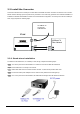
A.3 Fiber Optical Cable Connection Parameter The wiring details are as below: ■ Fiber Optical patch Cables: Standard Fiber Type Cable Specification 100Base-FX Multi-mode 50/125μm or 62.5/125μm 100Base-FX Multi-mode 50/125μm or 62.5/125μm (1310nm) Single-mode 9/125μm 100Base-BX-U Single-mode 9/125μm (1300nm) (TX :1310/RX :1550) 100Base-BX-D (TX :1550/RX :1310) A.4 Power Information The power jack of FT-90X is with 2.5mm in the central post and required +5VDC power input.