
User's Manual


User’s Manual of GS-6320 Series Managed Switch
28
2. INSTALLATION
This section describes the hardware features and installation of the Managed Switch on the desktop or rack mount. For easier
management and control of the Managed Switch, familiarize yourself with its display indicators, and ports. Front panel
illustrations in this chapter display the unit LED indicators. Before connecting any network device to the Managed Switch,
please read this chapter completely.
2.1 Hardware Description
2.1.1 Switch Front Panel
The front panel provides a simple interface monitoring the Managed Switch. Figures 2-1-1 show the front panels of the
Managed Switches.
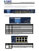
GS-6320-24UP2T2XV Front Panel
Figure 2-1-1: Front Panel of GS-6320-24UP2T2XV
■
Gigabit TP interface
10/100/1000BASE-T Copper, RJ45 twisted-pair: Up to 100 meters
■
10Gigabit TP interface
10M/100M/1G/2.5G/5G/10G BASE-T Copper, RJ45 twisted-pair: Up to 100 meters
■
10 Gigabit SFP+ slot
10GBASE-SR/LR mini-GBIC slot, SFP+ (Small Factor Pluggable Plus) Transceiver module supports from 300 meters
(multi-mode fiber) up to 60 kilometers (single mode fiber). The 10G SFP+ slots are backward compatible with 1000BASE-X
SFP and 2500BASE-X SFP transceivers.
■
Console port
The console port is a RJ45 port connector. It is an interface for connecting a terminal directly. Through the console port, it
provides rich diagnostic information including IP address setting, factory reset, port management, link status and system
setting. Users can use the attached DB9 to RJ45 console cable in the package and connect to the console port on the
device. After the connection, users can run any terminal emulation program (Hyper Terminal, ProComm Plus, Telix,
Winterm and so on) to enter the startup screen of the device.