
User's Manual


User’s Manual of GS-6320 Series Managed Switch
30
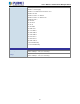
2.1.2 LED Indications
The front panel LEDs indicate instant status of power and system status, Ring, port links and data activity; they help monitor and
troubleshoot when needed. Figures 2-1-2 show the LED indications of the Managed Switches.
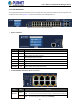
Figure 2-1-2: Front Panel of GS-6320-24UP2T2XV
System and Power
LED Color Function
AC Green Lights to indicate that the Switch has power from AC
DC Green Lights to indicate that the Switch has power from DC
SYS Green
Lights to indicate the system is working.
Off to indicate the system is booting.
FAN 1 Red
Lights to indicate that FAN1 is down.
FAN 2 Red Lights to indicate that FAN2 is down.
FAN 3 Red Lights to indicate that FAN3 is down.
PoE PWR Red Lights to indicate that the PoE power is down.
10/100/1000BASE-T Interfaces (Port-1 to Port-24)
LED Color Function
Ethernet
Green
Lights: To indicate that the port is operating at 1000Mbps.
Blinks: To indicate that the switch is actively sending or receiving data over that port.
Orange Lights: To indicate that the port is operating at 10/100Mbps.