24-Port 10/100/1000Mbps with 16-Port SFP Web Smart Ethernet Switch GSW-2416SF User’s Manual -1-
Trademarks Copyright © PLANET Technology Corp. 2006. Contents subject to revision without prior notice. PLANET is a registered trademark of PLANET Technology Corp. All other trademarks belong to their respective owners. Disclaimer PLANET Technology does not warrant that the hardware will work properly in all environments and applications, and makes no warranty and representation, either implied or expressed, with respect to the quality, performance, merchantability, or fitness for a particular purpose.
TABLE OF CONTENTS 1. INTRODUCTION ...................................................................................................................................................... 4 1.1 CHECKLIST................................................................................................................................................................ 4 1.2 ABOUT THE SWITCH ................................................................................................................................
1. INTRODUCTION 1.
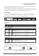
◆ Support CSMA/CD protocol ◆ 100~240VAC, 50~60Hz universal Power input ◆ FCC, CE class A compliant 1.4 Specification Model 10/100/1000Base-T Ports Console Switch architecture MAC address Switch fabric Throughput Flow Control GSW-2416SF 24 port RJ-45 10/100/1000Mbps, Auto Negotiation, Auto-MDI/MDI-X 16 port 3.
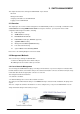
2. HARDWARE DESCRIPTION This product provides both Copper and Fiber connecter at same switch – 24 Ports TP and 16 Ports SFP (shared with Port #9 to 24), and automatically distinguishes the speed of incoming connection. This section describes the hardware features of GSW-2416SF. For easier management and control of the Switch, familiarize yourself with its display indicators, and ports. Front panel illustrations in this chapter display the unit LED indicators.
Power Notice: 1. The device is a power-required device, it means, it will not work till it is powered. If your networks should active all the time, please consider using UPS (Uninterrupted Power Supply) for your device. It will prevent you from network data loss or network downtime. 2. In some area, installing a surge suppression device may also help to protect your GSW-2416SF from being damaged by unregulated surge or current to the GSW-2416SF. 2.
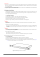
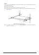
Caution: You must use the screws supplied with the mounting brackets. Damage caused to the parts by using incorrect screws would invalidate your warranty. Step 3: Secure the brackets tightly. Step 4: Follow the same steps to attach the second bracket to the opposite side. Step 5: After the brackets are attached to the Switch, use suitable screws to securely attach the brackets to the rack, as shown in Figure 2-4.
3. SWITCH MANAGEMENT This chapter describes how to manage the GSW-2416SF. Topics include: - Overview - Management methods - Assigning an IP address to the GSW-2416SF - Logging on to the GSW-2416SF 3.1 Overview This chapter gives an overview of switch management. The GSW-2416SF provides a user-friendly, command line under console interface and Simply WEB browser interface.
3.2.2 Web Management You can manage the GSW-2416SF remotely by having a remote host with web browser, such as Microsoft Internet Explorer or Netscape Navigator. Using this management method: The GSW-2416SF must have an Internet Protocol (IP) address accessible for the remote host. 3.3 Assigning an IP Address to the Switch To manage the GSW-2416SF remotely through the web browser with a Management Station, you must assign an IP address to the GSW-2416SF. To set the IP address, please use “set ip xxx.xxx.
3.4 Logging on to the GSW-2416SF When you log on to the GSW-2416SF console port for the first time, a sign-on string appears and you are prompted for a console login user name and password. The factory default login username is admin without password. #Notice: 1. For security reason, please change and memorize the new password after this first setup. 2. Only accept command in lowercase letter under console interface.
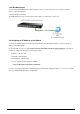
4. CONSOLE INTERFACE 4.1 CONNECT TO PC RS-232 serial cable Use the bundled RS-232 serial cable and attach the 9-pin female connector to the male connector on the GSW-2416SF. Plug the other side of this cable to your PC.
4.2 Login in Login is required to access the console interface after the self-test completes successfully. The factory default user name is "admin" without password. You may change the password by use “set pass” command. Please always enter the correct user name and password. (See Figure 4-2) Figure 4-2 GSW-2416SF login screen 4.3 Main Menu screen After login the GSW-2416SF, the main menu screen shows as below.
4.4 Getting Started 4.4.1 General Guidelines The GSW-2416SF allows users to configure the device via command line under console interface. Please type “help” or “?” for all available commands in the”GSW-2416SF>” prompt. The screen of available commands in Figure 4-4 appears, and the detail description shown in Table 4-1. Figure 4-4 GSW-2416SF available commands screen Command Description show port Show all port current status of GSW-2416SF. show static [n] Show per port TX/RX static of GSW-2416SF.
set flowcontrol [n] enable/disable Enable/Disable the flow control function to specific port [n] of GSW-2416SF. set vlantag [n] enable/disable Enable/Disable the VLAN Tagging to specific egress port of GSW-2416SF. set vlanaware [n] enable/disable Enable/Disable VLAN-Aware function to specific port of GSW-2416SF. set priority [n] [m] Allow to configure the priority setting of GSW-2416SF. set pvid [n] [m] Assign PVID on each port of GSW-2416SF.
show flowcontrol : Please refer to chapter 4.4.2.6. show vlantag : Please refer to chapter 4.4.2.7. show vlanaware : Please refer to chapter 4.4.2.8. show priority : Please refer to chapter 4.4.2.9. show pvid : Please refer to chapter 4.4.2.10. show vid : Please refer to chapter 4.4.2.11. 4.4.2.1 Show port Display the status on each port of GSW-2416SF, this command allows you to view the port status of the Switch and the correct usage is shown as below: Show port: to view all port status of GSW-2416SF.
Figure 4-7 Per port static screen #Notice: The TX/RX packets counted with error might because: z Packet with a bad FCS. z Packets were less than 64 bytes or greater than 1522 bytes. z Packets were dropped due to lack of resources. 4.4.2.3 Show vlan [n] Display one specific VLAN group status of GSW-2416SF. GSW-2416SF supports up to 24-port based VLAN Groups and the correct usage is shown as below: Show vlan to view all VLAN Group and port member assigned status.
4.4.2.4 Show ip Display the current IP address, netmask and gateway of GSW-2416SF. The IP subnet address information screen in Figure 4-9 appears. Figure 4-9 IP subnet address information screen 4.4.2.5 Show version Display the system information of GSW-2416SF, such as current software version and issued hardware version. The version information screen in Figure 4-10 appears.
4.4.2.6 Show flowcontrol Display the flow control status on all ports of GSW-2416SF, this command allows you to view per port flow control status of the Switch. Enabled – 802.3x flow control is enabled on Full-Duplex mode or Backpressure is enabled on Half-Duplex mode.. Disabled – No flow control or backpressure function on no matter Full-Duplex or Half-Duplex mode. The flow control status screen in Figure 4-11 appears. Figure 4-11 All ports flow control status screen 4.4.2.
4.4.2.8 Show vlanaware Display current VLAN-aware status on each port of GSW-2416SF. Enabled – Tagged Frame remain original VID while leaving tagged port. Disabled - Tagged Frame wouldn’t remain original VID while leaving tagged port. The VLAN-aware status screen in Figure 4-13 appears. Figure 4-13 The VLAN-aware status screen 4.4.2.9 Show priority Display the current priority status of GSW-2416SF.The allowed priority values are from 0-7. The priority status display screen in Figure 4-14 appears.
4.4.2.10 Show pvid Display the current per port PVID of GSW-2416SF. The Allowed PVID values are form 0-4095. The per port PVID display screen in Figure 4-15 appears. Figure 4-15 Display PVID screen 4.4.2.11 Show vid Display the current VLAN ID of each VLAN Group, the VLAN Groups and ID mapping status display screen in Figure 4-16 appears.
4.4.3 Set command From the main menu screen (see Figure 4-3), input “set” and press enter. The set command list screen in Figure 4-17 appears. Figure 4-17 Set command list screen This set command list contains ten items: Set port [n]: Please refer to chapter 4.4.3.1. Set vlan [n]: Please refer to chapter 4.4.3.2. Set flowcontrol [n] enable/disable: Please refer to chapter 4.4.3.3. Set vlantag [n] enable/disable: Please refer to chapter 4.4.3.4 Set vlanaware [n] enable/disable: Please refer to chapter 4.4.
4.4.3.1 Set port [n] This command allows configuring per port parameters of GSW-2416SF. the correct usage is shown as below: Set port [n]: n=1-24, to configuring per port parameters of GSW-2416SF. Default setting: (1) Auto Speed The configuring per port parameters screen in Figure 4-18 appears and the detail description shown in table 4-2.
Figure 4-19 VLAN members Configuration screen #Notice: Change VLAN settings for every time, you have to reboot the switch to apply new settings. 4.4.3.3 Set flowcontrol This command allows configuring per port flow control function of GSW-2416SF. The correct usage is shown as below: Set flowcontrol [n] enable/disable [n]=1-24, n is the specific Port ID. Enable – 802.3x flow control is enabled on Full-Duplex mode or Backpressure is enabled on Half-Duplex mode.
4.4.3.4 Set vlantag This is an additional function of VLAN configuration. This command allows configuring per port VLAN Tagged/Untagged status. When adding a VLAN to selected port, it tells the switch whether to keep or remove the tag from a frame on egress. The correct usage is shown as below: Set vlantag [n] enable/disable [n]=1-24, n is the specific Port ID. Enable – keep the tag from a frame on egress. Disable – Remove the tag from a frame on egress.
Figure 4-22 VLAN aware Configuration screen #Notice: Change VLAN settings for every time, you have to reboot the switch to apply new settings. 4.4.3.6 Set priority This command configures the default 802.1p port priority assigned for untagged packets for a specific port of GSW-2416SF. The correct usage is shown as below: Set priority [n] [m] [n]=1-24, n is the specific Port ID of GSW-2416SF. [m] = 0-7, m is 802.1p priority. Default Setting: 0 The per port priority setting screen in Figure 4-23 appears.
4.4.3.7 Set pvid This is an additional function of VLAN configuration. This command allows assign PVID for selected port of GSW-2416SF. The correct usage is shown as below: Set pvid [n] [m] [n]=1-24, n is the specific Port ID of GSW-2416SF. [m] = 1-4095, 0 reserved for management purpose; m is allowed VLAN ID. Default Setting: 0 To remote control the GSW-2416SF, the connect port have to set with PVID=0 The PVID setting screen in Figure 4-24 appears.
Figure 4-25 VID Configuration screen #Notice: Change VLAN settings for every time, you have to reboot the switch to apply new settings. 4.4.3.9 Set ip xxx.xxx.xxx.xxx.mmm.mmm.mmm.mmm.ggg.ggg.ggg.ggg This command allows assign IP address, netmask and gateway of GSW-2416SF. The correct usage is shown as below: set ip 192.168.0.1 255.255.255.0 192.168.0.254 and press After the setting be completed, you can use the new IP address to access the WEB UI of GSW-2416SF. Default Setting: IP: 192.168.0.
Figure 4-26 IP subnet address configuration screen 4.4.3.10 Set pass This command allows assign password of GSW-2416SF. The correct usage is shown as below: set pass [oldpass] [newpass] Default Setting: no password #Notice: The symbol “[“ and “]” are required for both old password and new password. And once the setting be completed, the next time login have to use the new password. The password setting screen in Figure 4-27 appears.
4.4.4 Factory default This command allows rest GSW-2416SF to factory default mode. The factory default screen in Figure 4-28 & 4-29 appears.
4.4.5 Reboot This command allows reboot GSW-2416SF, the reboot screen in Figure 4-30 & 4-31 appears.
4.4.6 Logout This command provides logout the GSW-2416SF, the screen in Figure 4-32 appears.
4.5 Firmware Update This section will show you how to use X-modem to update the firmware of GSW-2416SF. Firmware update requirements GSW-2416SF switch Latest firmware version VT100 terminal, or a personal computer or workstation with terminal emulation software RS-232/DB9 null modem cable Update procedure: 1. After login the GSW-2416SF, enter “update” in the”GSW-2416SF>” prompt. Then the message will ask you to use the Xmodem to send the firmware file.
Figure 4-34 Firmware Update Figure 4-35 Xmodem transmit After the file send be completed, the system will reboot automatically to the login screen. You can check if the Software version been updated.
5. WEB MANAGEMENT Before login the Web interface of GSW-2416SF, please setup the “IP Address” with local serial console port (RS232 port) and use this IP address to configure GSW-2416SF through the Web interface. Or modify your PC’s IP domain to the same with GSW-2416SF then use the default IP address (192.168.0.100) to remote configure GSW-2416SF through the Web interface. 5.
5.2 Port Config This section provides current ports status and detail setting of each port of GSW-2416SF. The screen in Figure 5-3 appears and Table 5-1 describes the port configuration object of switch. Figure 5-3 GSW-2416SF Port Configuration Web Page screen #Notice: Due to VID value “0” is reserved for management purpose, the management linked port have to configured with PVID=0. For example: The management PC connected to Port-24 of the switch via Ethernet.
Object Description Port Indicate port 1 to port 24. Mode Allow configuring the port speed and operation mode. Draw the menu bar to select the mode. z z z z z z z Flow Control Auto Speed - Setup Auto negotiation. 10 half - Force sets 10Mbps/Half-Duplex mode. 10 Full - Force sets 10Mbps/Full-Duplex mode. 100 half - Force sets 100Mbps/Half-Duplex mode. 100 full - Force sets 100Mbps/Full-Duplex mode. 1000 full - Force sets 10000Mbps/Full-Duplex mode. Disable - Shutdown the port manually.
5.3 VLAN Setup A Virtual LAN (VLAN) is a logical network grouping that limits the broadcast domain. It allows you to isolate network traffic so only members of the VLAN receive traffic from the same VLAN members. Basically, creating a VLAN from a switch is logically equivalent of reconnecting a group of network devices to another Layer 2 switch. However, all the network devices are still plug into the same switch physically. The GSW-2416SF switch supports Port-Base VLAN setting in web management page.
5.3.2 VLAN setting example: 5.3.2.1 Two separate VLAN The diagram shows how the switch handle Tagged and Untagged traffic flow for two VLANs. VLAN Group 2 and VLAN Group 3 are separated VLAN. Each VLAN isolate network traffic so only members of the VLAN receive traffic from the same VLAN members. The screen in Figure 5-5 appears and Table 5-2 describes the port configuration of switch.
Setup steps 1. VLAN Group Set VALN Group 1 = default-VLAN with VID (VLAN ID)=1 Add two VLANs – VLAN 2 and VLAN 3 VLAN Group 2 with VID=2 VLAN Group 3 with VID=3 2. Assign VLAN Member : VLAN 2: Port-1, Port-2 and Port-3 VLAN 3: Port-4, Port-5 and Port-6 VLAN 1: All other ports – Port-7~Port-24 3. Assign PVID for each port: Port-1, Port-2 and Port-3: PVID=2 Port-4, Port-5 and Port-6: PVID=3 Port-7~Port-24: PVID=1 4.
Figure 5-7 VLAN 1 member assign Web page screen Figure 5-8 VLAN 2 member assign Web page screen EM-GSW2416SFv1 - 41 -
Figure 5-9 VLAN 2 member assign Web page screen #Notice: Change VLAN settings for every time, you have to reboot the switch to apply new settings. 5.3.2.2 Overlap VLAN The scenario described as follow: 1. Port-16 is the file server port for all the workstations 2. Port-1 to Port-15 is different devices that do need to see each other Setup steps 1. Port Setting 1.1 Assign VLAN 1 as the default VLAN group for all ports 1.2 Assign VLAN 2 for the second VLAN group with Port-1 and Port-16 1.
5.4 Port Trunk Setup This section allows you to disable or enable trunk function of two ports or four ports together to speed up data transmission. The GSW-2416SF provides up to 3 Trunk group, each group supports maximum 4 ports, the screen in Figure 5-10 appears. Figure 5-10 GSW-2416SF Port Trunk Setup Web Page screen To configure the Port Trunk, with the specific Trunk ID, select Member ports to meet required.
#Notice: 1. After turn on the port trunk feature, port 1 and port 2 or port 17,18,19,20 should connect to another switch, such as another GSW-2416SF, that also supports port trunk feature to double the bandwidth in between. Otherwise, if the connected switch do not support port trunk, it will cause network loop and hangs the whole network. 2. The GSW-2416SF doesn’t support LACP (Link Aggregation control Protocol) trunk type yet. Connect with LACP type switch the trunk function might be failed. 3.
5.5 Status 5.5.1 Port Status This section displayed the current link status of each port on GSW-2416SF. It’s help the manager easy to get the connection info. The screen in Figure 5-12 appears. Figure 5-12 GSW-2416SF Port Status Web Page screen 5.5.2 Statistics This section displayed the current traffic statistics of each port on GSW-2416SF. The screen in Figure 5-13 appears. The content of the statistics table include the following items: z TX OK: Number of transmitted packets.
Figure 5-13 GSW-2416SF Port Statistics Web Page screen There’re also two buttons at the statistics web page – “Clear” and “Refresh”. Press the “Clear” button will clear the current traffic statistic value. Press the “Refresh” button will update the latest traffic statistic value, especially for the traffic keeps on transmitting.
5.6 Misc Configuration This section provides Misc Configuration of GSW-2416SF. 5.6.1 System Setup This section provides System Configuration of GSW-2416SF, the screen in Figure 5-14 appears and table 5-4 descriptions the System Configuration objects of GSW-2416SF. Figure 5-14 GSW-2416SF System Configuration Web Page screen Object Description Mac address Display Mac address of GSW-2416SF. S/W Version Display firmware version of GSW-2416SF.
5.7 Tools This section provides two management tools of GSW-2416SF- Reboot and Factory Reset. 5.7.1 Reboot This section provides reboot GSW-2416SF, after choose this function and the following screen appears in Figure 5-15. Please press “Warm Reboot” button to take effect immediately. After system reboot, the manager has to refresh the browser and re-login web interface with correct username “admin” and password, the screen in Figure 5-16 appears.
5.7.2 Factory Reset This section provides reset GSW-2416SF to factory default mode, default value to as following configuration: z Default IP address: 192.168.0.100 z Subnet mask: 255.255.255.0 z Default Gateway: 192.168.0.254 z The other setting value is back to disable or none. After choose this function and the following screen appears in Figure 5-17.
5.8 Logout This section allows to logout the GSW-2416SF. Press “Logout” item in the Web Menu, it take effect immediately. If the manager wants to re-login, press the “Re-Login” button. The screen in Figure 5-19 and Figure 5-20 appears.
6. SWITCH OPERATION 6.1 Address Table The Switch is implemented with an address table. This address table composed of many entries. Each entry is used to store the address information of some node in network, including MAC address, port no, etc. This information comes from the learning process of Ethernet Switch. 6.2 Learning When one packet comes in from any port. The Switch will record the source address, port no. And the other related information in address table.
7.TROUBLESHOOTING This chapter contains information to help you solve problems. If the Switch is not functioning properly, make sure the Ethernet Switch was set up according to instructions in this manual. The Link LED is not lit Solution: Check the cable connection and remove duplex mode of the Switch. Some stations cannot talk to other stations located on the other port Solution: Please check the VLAN, port trunking function that may introduce this kind of problem.
APPENDIX A NETWORKING CONNECTION A.1 Switch‘s RJ-45 Pin Assignments 10/100Base-TX Contact 1 MDI 1 (TX +) MDI-X 3 2 2 (TX -) 6 3 3 (RX +) 1 6 6 (RX -) 2 4, 5, 7, 8 Not used Not used A.
Figure A-1: Straight-Through and Crossover Cable Please make sure your connected cables are with same pin assignment and color as above picture before deploying the cables into your network.