Internet Camera ICA-100/ICA-100W User’s Manual
Copyright Copyright (C) 2003 PLANET Technology Corp. All rights reserved. The products and programs described in this User ’s Manual are licensed products of PLANET Technology, This User’s Manual contains proprietary information protected by copyright, and this User’s Manual and all accompanying hardware, software, and documentation are copyrighted.
TABLE OF CONTENTS CHAPTER 1 INTRODUCTION ...................................................................................... 1 ICA-100/ICA-100W Features ................................................................................. 1 Package Contents ................................................................................................. 2 Physical Details ..................................................................................................... 2 CHAPTER 2 INSTALLATION ...........
Chapter 1 Introduction 1 This Chapter provides an overview of Internet Camera 's features and capabilities. Internet Camera provides a low cost solution for enterprise and SOHO users to enhance the ability of network environment. By connecting directly to an Ethernet or Fast Ethernet, the high quality video image can be monitored everywhere. The main difference from the conventional PC Camera is that Internet Camera is a standalone system.
Broadband Router User Guide Motion Detection Monitor any suspicious movement in a specific area. Wired and Wireless Network Support.(ICA-100W only) ICA-100W provides both wired and wireless function. You can use ICA-100W in different LAN environment by simple mode switching.
Introduction There are three settings for the Power and LAN ( /WLAN ) LED to control the light illumination for monitoring purpose from Normal / Off / Dummy. Please refer to the Web Configuration section for detailed information and usage.
Broadband Router User Guide begins to light up, then release the reset button and the Power LED will begin to flash indicating ICA-100 is changing to factory reset. When factory reset is completed the IP address will return to the default setting as 192.168.0.20. Factory Reset of ICA-100W: Press the reset button for three seconds or until Power LED begins to light up, then release the reset button and the Power LED will begin to flash indicating ICA-100W is changing to factory reset.
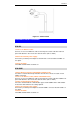
Introduction Figure 1-5:Top Panel of ICA-100W Screw Hole Located on the top panel of ICA-100 series, the screw hole is used to connect the camera stand onto ICA-100 series by attaching the screw head on the camera stand into the screw hole of ICA-100 series.
2 Chapter 2 Installation This Chapter covers the physical installation of ICA-100 Series. Requirements ICA-100 ICA-100W Network Environment LAN 10/ 100M Ethernet 10/ 100M Ethernet IEEE 802.11b Wireless LAN Monitoring System Recommended to Access ICA-100 series System Hardware Web Browser • CPU: Pentium II, 266 MHz or above • Memory Size: 32 MB (64 MB recommended) • VGA card resolution: 800x600 or above • Internet Explorer 5.
Installation Figure 2-1: Camera Stand Hardware Install Procedure ICA-100 1.Connect an Ethernet cable Connect one end of an Ethernet cable to the LAN port located on the ICA-100 rear panel and attach the other end to the network device (hub or switch). 2.Attach the external power supply Connect the provided power adapter to the ICA-100’s connector labeled "5VDC" on rare panel. 3.Check the LEDs The PWR and ACT LEDs should be on. ICA-100W 1.
Chapter 3 Configuration 3 This Chapter provides details of the software configuration process. Login ICA-100 series must be configured through its built-in Web-based Configuration. Extensive knowledge of LAN will be helpful in setting up. From the web browser, type http ://192.168.0.20 in the address box to access Home page of ICA-100 series.
PC Configuration Figure 3-1:Home Page System Administration Click on “System Administration” from the Home page to access the settings required for ICA-100 series. There will be several options in the menu bar to choose from to set your Internet Camera and they are as follows: • System • Image • Users • DateTime • Trigger • Upload • Information • Tools System The System menu contains commands for settings that are required for inputting key details to set-up ICA-100 series for operation.
Broadband Router User Guide 10
PC Configuration Figure 3-2: System Screen of ICA-100W Camera Name: This field is used for entering a descriptive name for the device. The default setting for the Camera Name is CS-xxxxxx, where xxxxxx is the last six digit of the MAC Address. The maximum length is 32 (Printable ASCII). Location: This field is used for entering a descriptive name for the location used by ICA-100 series.
Broadband Router User Guide Enter the URL of the DDNS service provider whom you registered to. Host Name Enter the hostname you registered. User Name Enter the user name that used to login the DDNS web site. Password Enter the password of your account. Wireless Interface: (ICA-100W only) Connection Mode: Use the Connection Mode to determine the type of wireless communication for ICA100W. There are three choices of Infrastructure mode, 802.11 Adhoc mode and Adhoc mode.
PC Configuration Click on ASCII or HEX check box to select input format as ASCII format or HEX format, and then input WEP key. To Confirm the WEP key you must enter the data once again in the Confirm WEP Key field. ASCII input format: ASCII format causes each character to be interpreted as an eight-bit value. All unaccented upper- and lower-case Western European characters that can be input through your keyboard's typing zone are valid.
Broadband Router User Guide Note: This function is built-in to the LED indicators to add extra capabilities. The three options allow the Administrator to configure and camouflage the illumination for the LED indicator to falsify the monitoring status. In Normal Mode the LED indicator functions as normally. Under Off Mode the LED indicators are both off however, it is still monitoring the activity. In Dummy Mode the LED indicators operate in monitoring condition but monitoring activity is off or on.
PC Configuration Image Image menu in the system administration contains commands to provide the settings for the images captured by ICA-100 series. Click on “Image” in the system administration menu bar and the Image screen will appear as illustrated below: Figure 3-3: Image Screen Video Resolution: Select the desired video resolution format ranging from 320x240 (default) or 640x480. Compression Rate: Select the desired compression rate with five levels from very low to very high.
Broadband Router User Guide After making sure all settings in the Image are correct, click on the “Save” icon to store the settings for ICA-100 series. You can alternatively click on the “Cancel” icon to restore all settings to the values last saved to or retrieved from ICA-100 series. Users The User options menu contains commands to allow system administrator to assign legal users who are permitted to monitor ICA-100 series from the remote site.
PC Configuration Figure 3-5: User Login Screen DateTime The DateTime menu contains commands for setting ICA-100 series' time and date requirements to provide correct information to users who might be thousands of miles away in the remote site. There are two options to select from the DateTime menu bar either Synchronized with Time Server or Set Manually.
Broadband Router User Guide Note: Please find below NTP server web address for your reference to set the time server. http://www.eecis.udel.edu/~mills/ntp/clock1.htm http://www.eecis.udel.edu/~mills/ntp/clock2.htm Protocol: Two options of NTP or Time are available for your selection to link with the Time Server. The default setting is NTP. TimeZone: System administrator must select the time zone for the region. Please refer to the appendix for the time zone selection table.
PC Configuration Figure 3-7: Trigger Screen The default setting for the I/O Trigger functions are disabled. You must enable the I/O Trigger first before the Triggers will perform. There are two options to select from the Trigger screen I/O Input 1 Trigger and I/O Input 2 Trigger. I/O Input 1 Trigger: Select “Send e-mail attached with image” and enter the relevant information such as the SMTP Server Address, Sender e-mail Address, Receiver e-mail Address, Sending Interval and Sending Times.
Broadband Router User Guide The period of time between each email being sent to the receiver. If the setting is at 10 seconds, a new e-mail will be sent in 10 seconds interval to the receiver. Sending Time The number of times the e-mail will be sent to the receiver before it terminates. Select “Trigger I/O Output” and enter the setting for Output 1 time and Output 2 time in seconds. These fields determine the duration for activating the external output devices.
PC Configuration Figure 3-8: Upload Screen FTP Server: Host Address: Enter the IP address of target FTP server. Port Number: Most of the FTP servers using port 21. If the target FTP server uses specific port, please ask the FTP server administrator to provide the information. User Name: Enter the user name used to login FTP server in this field. Password: Enter the password used to login FTP server in this field.
Broadband Router User Guide Enter a folder name which already exists in FTP server, then the images will be uploaded to the given folder. Passive Mode: Some FTP servers use passive mode. Please confirm this with the FTP server administrator. Time Schedule: Enable “Upload image to FTP server” and enter the appropriate information such as the schedule, image frequency and base file name.
PC Configuration Figure 3-9: Information Screen The Information table provides detailed information of ICA-100 series such as the Model Name, Firmware Version, Mac Address, and IP Address. Tools The Tools menu contains commands for restarting ICA-100 series.
Broadband Router User Guide manually by turning the lens clockwise or anti-clockwise to the desire image quality. Please refer to the appendix for detailed information regarding Adjust Internet Camera Focus and Replacing the Lens. View Image- ActiveX Mode Before using ActiveX mode to view image, the Xplug Control (ActiveX) plug-in program must install into the PC/Notebook first.
PC Configuration Administration.
Broadband Router User Guide Chapter 4 IPView Installation 4 This Chapter details the installation procedure of IPView utility. Install Procedure STEP 1 Insert the CD-ROM into the CD-ROM drive to initiate the autorun program. Once completed a menu screen will appear as follows: Figure 4-1: Menu Screen STEP 2 To install the IPView Application click on the "IPView" hyperlink to activate the installation procedure for the application program.
PC Configuration Figure 4-2: Welcome Screen STEP 4 The License Agreement prompt will appear as below. Read the details carefully and click on the “Yes” icon to continue with the installation procedure.
Broadband Router User Guide Figure 4-3: License Agreement STEP 5 A prompt will appear and in the Destination Location dialog box, you may click on “Next” to accept the recommended destination location or click on “Browse” to select another location. After specifying the desired destination location, click on “Next” to proceed further.
PC Configuration Figure 4-5: Select Program Folder STEP 7 Please wait until Figure 4-7 or Figure 4-8 appears. Select “Yes, I want to restart my computer now” and click on the “Finish” icon to restart the computer in Figure 4-7. If Figure 4-8 appears, click on the “Finish” icon to complete the installation procedure.
Broadband Router User Guide Figure 4-7: Finish Screen Launch IPView After successfully installing the IPView, the application program is automatically installed to \Program Files\IPView. Click on Start Menu/Programs/IPView/IPView to launch the program.
PC Configuration Figure 4-8: IPView Path Once IPView is executed, a Login dialog box will appear, you must enter the default User Name: admin into the respective field and click on “OK” to log into the application.
Broadband Router User Guide After login, the IPView application is executed and its interface will appear as follows in the default List View format: Figure 4-10: List View Format 32
Chapter 5 Use of IPView 5 This chapter describes operation of the IPView application interface with detailed procedures for using the application. Overview IPView is responsible for the management of preview, configuration, and searching of each camera. It is designed with a user-friendly interface for ease of control and navigation requirements as illustrated below.
Broadband Router User Guide Note: Alternatively you can click the Options icon “F10”. as illustrated or use the hot key Menu Bar The menu bar provides easier access for users to navigate the IPView with different selections along with hot key capabilities as follows: File “File” on the menu bar provides “New”, “Open”, “Save”, “Save As” and “Exit” for users to create new files, open existing files, save files, and exit the IPView as depicted below.
Advanced Configuration Figure 5-3: View Screen Camera “Camera” on the menu bar provides options to manage the camera. One can “Add” additional Camera with a maximum of 16 Camera allowed for viewing. Through the management function one can “Delete” a camera, manage the “Property”, “Enable” for real time and take a “Snap shot” image. The menu bar is illustrated below: Figure 5-4: Camera Screen By default the video image is enabled.
Broadband Router User Guide the menu bar select "Tools” > "Options" and a dialog box will appear. Administrator can change the User Name and Password for security settings to access the application. Figure 5-5: Tools Screen Help “Help” on the menu bar provides “Contents” and “About” to assist users how to operate the camera in HTLM format.
Advanced Configuration Figure 5-8: Warning Message If you are unsure of the IP Address of the camera you can click on the “Browse” icon, the Browse Camera dialog box will appear with a blank screen as illustrated below.
Broadband Router User Guide Figure 5-10: Search for Camera Select the camera want to add and click on the “Add” icon. The Add Camera dialog box will appear again with the IP Address entered. Click on the “Add” icon and the camera will be automatically added into IPView list view format. Alternatively you can double click on the camera and the Add Camera dialog box will appear again with the IP Address entered. Click on the “Add” icon and the camera will be automatically added into IPView list view format.
Advanced Configuration Enter the correct User Name and Password to add camera in the list. Please note that only one camera can be added at a time. Delete Camera Select the camera wants to delete from IPView list view format. From the menu bar select “Camera” > “Delete” or click from toolbar or use hot-key “Del”. A Delete Camera dialog box will appear and click on the “Yes” icon to delete the camera or click on “No” if you do not want to delete the camera.
Broadband Router User Guide Snap Shot To snap shot a single image, highlight the camera you wish to snap shot from the list from toolbar view format. Select “Camera” > “Snap shot” from menu bar or click or use the hot-key “F5”. A Save Image dialog box will appear for specifying the path of snap shot picture. Or from the viewing mode either 1, 4, 9, 16 cameras right click on the icon located on the upper left corner of the screen and a menu will appear and select the “Snap shot” icon.
Advanced Configuration Figure 5-14: General Screen IP Assignment There are two options to select from the IP Assignment either Manually Assign or Assign Automatically Using. Please refer to Chapter 3 Configuration à System Administration à System section for further details.
Broadband Router User Guide Figure 5-15: IP Assignment Screen DNS DNS (Domain Name System) server is an Internet service that translates domain names into IP addresses. Enter at least one DNS IP Address. Please refer to Chapter 3 Configuration à System Administration à System section for further details.
Advanced Configuration Figure 5-16: DNS Screen Wireless (Please skip this section if your camera is not wireless.) Allows setting for connection mode, network name, wireless channel, and WEP key. Please refer to Chapter 3 Configuration à System Administration à System section for further details.
Broadband Router User Guide Figure 5-17: Wireless Screen Misc Allows setting for LED Control, ActiveX control location, and second port. Please refer to Chapter 3 Configuration à System Administration à System section for further details.
Advanced Configuration Figure 5-18: Misc Screen Image Image provides the settings for the video image of the camera such as brightness, contrast, saturation, resolution, compression, frame rate, and light frequency. Please refer to Chapter 3 Configuration à System Administration à Image section for further details. Regarding the Date Display field, there are three available options: No Display, Opaque Mode, and Transparent Mode.
Broadband Router User Guide Figure 5-19: Image Screen User This option allows system administrator to assign legal users who are permitted to monitor the camera from the remote site by Add or Delete user.
Advanced Configuration Figure 5-20: User Screen To add a user click on the “Add” icon and the Add User dialog box will appear. Enter the User Name and Password into the specific field. Select the I/O Output Control to give users the privilege of accessing the I/O Output Control. Figure 5-21: Add User Screen To delete a user, select the user and click on the “Delete” icon. Please refer to Chapter 3 Configuration à System Administration à Users section for further details.
Broadband Router User Guide Date/Time Provides two settings of adjusting the camera’s time and date: Synchronized with Time Server or Set Manually. Please refer to Chapter 3 Configuration à System Administration à DateTime section for further details. Figure 5-22: Date/Time Screen Trigger 1 Provides the settings of first set I/O trigger connectors. Please refer to Chapter 3 Configuration à System Administration à Trigger section for further details.
Advanced Configuration Figure 5-23: Trigger1 Screen Trigger 2 Provides the settings of first set I/O trigger connectors. Please refer to Chapter 3 Configuration à System Administration à Trigger section for further details.
Broadband Router User Guide Figure 5-24: Trigger2 Screen Information Displays information about the camera such as the model, firmware version, MAC address, and IP address. Please refer to Chapter 3 Configuration à System Administration à Information section for further details.
Advanced Configuration Figure 5-25: Information Screen Tools Proving functions for reset the camera and update firmware. Please refer to Chapter 3 Configuration à System Administration à Tools section for further details on reset. Firmware Upgrade Procedure: 1. Download the latest firmware to a PC . 2. Activate IPView, select “Camera” > “Properties” and the Camera Property dialog box will appear. 3.
Broadband Router User Guide Figure 5-26: Tools Screen 52
Advanced Configuration Recording Figure 5-27: Recording Screen Recording File Path: There are four file paths can be set here and only one of them is working at one time. It is suggested to set them to different disk drives. For example: set path 1 to C drive, and set path 2 to D drive. Once C drive run out of its disk space, IPView will switch the file path to path 2 automatically so that the recording task won’t be interrupted.
Broadband Router User Guide Manual Manually control the recording operation. Schedule Mode Select this option and click “Advanced Setting” for detailed configurations. The predefined schedule can be set by date or weekday. Figure 5-28: Schedule Setting Screen Motion Active Mode Select this option and click “Advanced Setting” for detailed configurations. You can adjust the sensitivity level and choose the warning options when IPView detects a motion.
Advanced Configuration Figure 5-29: Motion Setting Screen 55
Broadband Router User Guide IPView Icon Description Create a new file. The alternative hot key is Ctrl+N. Open an existing file. The alternative hot key is Ctrl+O. Save a file. The alternative hot key is Ctrl+S. List view format. The alternative hot key is Ctrl+F1. 1 camera view format. The alternative hot key is Ctrl+F3. 4 cameras view format. The alternative hot key is Ctrl+F4. 9 cameras view format. The alternative hot key is Ctrl+F5. 16 cameras view format. The alternative hot key is Ctrl+F6.
Advanced Configuration Context Sensitive Meun Select a camera in list view format and right click the mouse, a context sensitive menu includes features of “Add”, “Delete”, “Property”, “Enable”, “Snap Shot”, and recording control options will appears. Figure 5-30: Context Sensitive Menu in List View Format In camera view format, click on the icon located at the upper left corner of the screen and a case sensitive menu will appear as illustrated below.
Broadband Router User Guide Figure 5-31: Case Sensitive Menu in Camera View Format 58
Appendix A Frequently Asked Questions A Internet Camera Features Q: What is an Internet Camera? A: The Internet Camera is a standalone system connecting directly to an Ethernet or Fast Ethernet network. And ICA-100W also supports the wireless transmission based on the IEEE 802.11b standard.
Broadband Router User Guide Q: Can the Internet Camera be setup as a PC-cam on the computer? A: No, the Internet Camera can be used only on Ethernet and Fast Ethernet network. Q: Can the Internet Camera be connected on the network if it consists of only private IP addresses? A: The Internet Camera can be connected to LAN with private IP addresses.
Appendix A - Troubleshooting Appendix B Trouble Shooting B Q: I cannot access the Internet Camera from a web browser? A: If ICA-100 series do not respond, check the following: • Machine is properly installed, LAN or WLAN connection is OK, and it is powered ON. You can test the connection by using the "Ping" command: Open the MS-DOS window or command prompt window. Enter the command: ping 192.168.0.
Broadband Router User Guide Q: There is bad focus on the Internet Camera, what should be done? A1: The focus might not be correctly adjusted for the line of sight. You need to adjust the Internet Camera focus manually as described in Appendix E: Adjust Internet Camera Focus. A2: The adaptor used is not fitted with your C-type lens. If you have previously changed the supplied CS-type lens, you may have unintentionally installed a C-type lens without fitting the adaptor first. Q: Noisy images occur.
Appendix C I/O Connectors C An 8-pole connector is provided for auxiliary I/O connections to ICA-100 series. The I/O connector provides the physical interface for 2 digital outputs and 2 digital inputs that is used for connecting a diversity of external alarm devices to ICA-100 series such as IR-Sensor and alarm relay. The digital input is used for connecting external alarm devices. Once triggered, images will be taken and e-mailed.
Broadband Router User Guide Warning 1. When connecting a device to the Input connector, the device must be a passive component without voltage and electrical current. 2. When connecting other devices through the Output connector, please make sure the maximum current of DC 5V, 100mA is strictly observed. 3. Any failure of the above two points might cause serious damage to the camera.
Appendix C - Specifications Appendix D Adjust Focus/ Replace Lens D The Internet Camera features an exchangeable CS-type lens that can be used for different applications as necessary. It supports rotational focus control so the lens can be adjusted to focus under normal and stable conditions to maximize the image quality of the Internet Camera.
Broadband Router User Guide Replace the Lens Since the Internet Camera is designed with a CS- mount, the lens equipped with the Internet Camera can be replaced with any standard C or CS lens commonly used within the surveillance industry. Follow the instructions below to replace the supplied lens with any C or CS type lens. 1. Unscrew the Internet Camera lens 2. C-lens only, attach the new lens to a CS-C adapter 3. Screw the new lens onto the Internet Camera.
Appendix C - Specifications Appendix E Install Xplug Control Utility E Install on Web Server STEP 1 Copy xplug.ocx to the home directory of a web server. STEP 2 Log on the Home page of ICA-100 series, click on the “System Administration” link. The system page will appear. STEP 3 Locate the “Loading ActiveX From” field on system page. Fill the field with web server’s address. Either IP address or Internet address will do.
Broadband Router User Guide 1. Click on Start Menu/ Run. 2. Enter “D:\ActiveX\xpctrl.exe” in the appeared box, where “D” is the letter of your CD-ROM drive. 3. Click on “OK” button. STEP 3 The Welcome screen will appear. Click on the “Next” button to proceed with the installation. STEP 4 The License Agreement will appear as below. Read the details carefully and click on the “Yes” icon to continue with the installation procedure.
Appendix C - Specifications STEP 5 Click on the “Finish” button to complete Setup of the Xplug Control Utility program for the Wireless Internet Camera.
Broadband Router User Guide 70
Appendix C - Specifications F Appendix F Specification ICA-100 ICA-100W Video Specification Resolution 640 x 480 pixel Sensor 1/3” color CMOS sensor Gain control Automatic Exposure Automatic White Balance Automatic Shutter Electronics 1/60 ~ 1/15000 sec Minimum Illumination 2.5lux@F1.4, 3000K color Focal Length 6.0 mm Aperture f=1.
Broadband Router User Guide Management Communication media 10/100Mbps Ethernet Communication protocol HTTP, FTP, TCP/IP, UDP, ARP,ICMP, BOOTP, RARP, DHCP, PPPoE Management Utility Internet Browser, Software Utility Utility Support OS Win 98, Win 98 SE, Win 2000, Win Me, Win XP • Live image viewing • Remote management • Snap shot • Picture recording • Motion detection Utility Function 10/100Mbps Ethernet, IEEE 802.
Appendix C - Specifications Appendix G Glossary of Terms G NUMBERS 10BASE-T 10BASE-T is Ethernet over UTP Category III, IV, or V unshielded twisted-pair media. 100BASE-TX The two-pair twisted-media implementation of 100BASE-T is called 100BASE-TX. A Applet Applets are small Java programs that can be embedded in an HTML page. The rule at the moment is that an applet can only make an Internet connection to the computer form which the applet was sent. ASCII American Standard Code.
Broadband Router User Guide network device that automatically assigns an IP address to any device that requests for it. DNS Domain Name System is an Internet service that translates domain names into IP addresses. Since domain names are alphabetic, they're easier to remember. The Internet however, is really based on IP addresses. Every time you use a domain name, the DNS will translate the name into the corresponding IP address. For example, the domain name www.network_camera.com might translate to 192.
Appendix C - Specifications for internal usage only. Internet The Internet is a globally linked system of computers that are logically connected based on the Internet Protocol (IP). The Internet provides different ways to access private and public information worldwide. Internet address To participate in Internet communications and on Internet Protocol-based networks, a node must have an Internet address that identifies it to the other nodes.
Broadband Router User Guide WAN – (wide area network): The computers are in different geographic locations and are connected by telephone lines or radio waves. NWay Protocol A network protocol that can automatically negotiate the highest possible transmission speed between two devices. P PING Packet Internet Groper, a utility used to determine whether a specific IP address is accessible. It functions by sending a packet to the specified address and waits for a reply.
Appendix C - Specifications stations. Subnet mask In TCP/IP, the bits used to create the subnet are called the subnet mask. T TCP/IP Transmission Control Protocol/Internet Protocol is a widely used transport protocol that connects diverse computers of various transmission methods. It was developed by the Department of Defense to connect different computer types and led to the development of the Internet. Transceiver A transceiver joins two network segments together.