IR IP Camera ICA-106 User’s Manual Version: 1.
Copyright Copyright© 2006 by PLANET Technology Corp. All rights reserved. No part of this publication may be reproduced, transmitted, transcribed, stored in a retrieval system, or translated into any language or computer language, in any form or by any means, electronic, mechanical, magnetic, optical, chemical, manual or otherwise, without the prior written permission of PLANET.
Safety This equipment is designed with the utmost care for the safety of those who install and use it. However, special attention must be paid to the dangers of electric shock and static electricity when working with electrical equipment. All guidelines of this and of the computer manufacture must therefore be allowed at all times to ensure the safe use of the equipment.
Table of Contents Chapter 1 1.1 1.2 1.3 1.4 1.5 Chapter2 2.1 Chapter3 3.1 Overview........................................................................................................ 5 Introduction ................................................................................................... 5 Features:......................................................................................................... 5 Application: .............................................................................
Chapter 1 Overview This user’s guide explains how to operate the Network Camera from a computer. This user’s guide is written to be read on the computer display. However, users might consider printing it out to access easily and read it before you operate the Network Camera. 1.1 Introduction This Network Camera is an inexpensive and fully scalable surveillance technology.
1.3 Application: z Remote monitoring z Surveillance 1.4 System Requirement z Microsoft Internet Explorer 5.5 or later z VGA Monitor resolution 1024 x 768 z Pentium4 1.3GHz or above z Memory Size: 256MB or above z Windows ME, 2000, XP, or 2003 1.5 Package Contents User can find the following items in the package: 1. 2. 3. 4. 5.
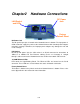
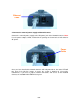
Chapter2 Hardware Connections DC Power Jack LAN Socket and LEDs Factory Default Reset DC Power Jack The DC power input jack is located on the Network Camera’s bottom. The input power is 5VDC. Note that supply the power to the Network Camera with standard power adapter included in package. Otherwise, the improper power adapter may damage the unit and result in danger. LAN Socket Beside the DC power Jack, the LAN socket is an RJ-45 connector for connections to 10Base-T or 100Base-TX Fast Ethernet cabling.
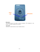
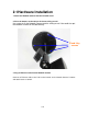
Status LED Microphone Microphone The Network Camera’s has built-in an internal microphone. This microphone is also hidden in the pinhole located on the front panel. Status LEDs This LED is used to indicate the status of Network Camera.
2.1 Hardware Installation 1. Attach the Network Camera with the included stand 2. Place the Camera on the table or fix it onto ceiling or wall Use screws to fix the Network Camera onto the ceiling or wall. You could also put the Network Camera on the table directly. Fixed it by screws 3. Plug an Ethernet cable into the Network Camera Connect an Ethernet cable to the LAN socket located on the Network Camera’s bottom and attach it to the network.
Ethernet Cable 4. Connect the external power supply to Network Camera Connect the external power supply to the DC power jack of the Network Camera. Note: Use the power adapter, 5VDC, included in the package and connect it to wall outlet for AC power. Power Cable Once you have installed the Network Camera well and powered on, the status LED will turn green first and then orange. It means the system is booting up successfully.
Chapter3 Login to Homepage 3.1 Before Operation Install the IP Address of Network Camera When you installed your Network camera on your LAN environment, you may execute “MP4 IP Finder.exe” to discover Network camera’s IP address. “MP4 IP Finder.exe” is used to scan the Installed Network Camera on a LAN, setting the Network Camera Name, IP address settings and so on.
5. The Network Camera will restart the system to validate the new setting after seconds. Alternatively, user can use another approach to search out the Network Camera on the LAN by UPnP as bellow: ® 3.2 Enabling UPnP for Windows XP™ UPnP™ is short for Universal Plug and Play, which is a networking architecture that provides compatibility among networking equipment, software, and peripherals. This device is an UPnP enabled Network Camera.
Click Add or Remove Programs Click Add/Remove Windows Components The following screen will appear: 13/60
Select Networking Services Click Details Select Universal Plug and Play Click Ok 14/60
Click Next Please wait while Setup configures the components.
Click Finish To view your Network Camera in an Internet browser, go to your Desktop and click My Network Places.
The last three digits (146), represent the fourth octet of your Network Camera’s IP address (in this example, 198.168.0.146). 3.3 Install the Camera with a Router The Network Camera can be used with a router. This section explains how to view the camera from either the Internet or from inside your LAN. If the Network Camera was installed on the LAN with a router, then it can get a dynamic IP address from the DHCP server.
(3) Open Virtual Server Ports to enable remote image viewing The firewall security features built into the most routers prevent users from accessing the video from the Network Camera over the Internet. The router connects to the Internet over a series of numbered ports. The ports normally used by the Network Camera are blocked from access over the Internet. Therefore, these ports need to be made accessible over the Internet. This is accomplished using the Virtual Server function on the router.
3.4 Before connected via web browser The Network Camera web page communicates with the Network Camera using an ActiveX control. The ActiveX control component must be installed on your PC in advance. To download ActiveX control component, user must install the Liveplayer application program. Please refer to Liveplayer manual for detail. By now, you have finished your entire PC configuration for Network Camera. 3.5 The first time access via web browser 1.
2. Type in your login name and password under “USERNAME” and “PASSWORD” textbox. For the first time use (default value), input the User Name: admin Password: admin That’s, type in “admin” on the “User Name” as a default name and “admin” on “Password”. Click “OK” button to start the main menu. Now, you login to the Network Camera as a full-authorized administrator. You can enter “Setting” to change the password and setup “Administrator” or “User” authority. Please refer to “Setting” Î “User” 3.
The second one is a user with “config” privilege. The “config” user can view the video and or audio streaming. Also user can change the settings in the “Home” and “Setting” pages except “user” and “Factory Default” options. Furthermore, “Capture” and “Recording” will be not available. 3.7 Logging in as an Administrator If you log in the Network Camera as the Administrator, you can perform all the settings provided within the software.
Chapter 4 Operating the Network Camera Start-up screen will be as follow no matter an ordinary users or an administrator. Advanced Function Viewing Area Control Panel Viewing Area: Images from the Network Camera Scale UP: Click this button to scale up the image on the screen Scale Down: Click this button to scale down the image on the screen Snap / Record to: Enter the path to save the image or files.
4.1 Control Panel Control Panel Area: Network Camera Manipulation and picture quality control Item Button Meaning 1 Quality Adjust video quality.
6 Contrast Adjust picture contrast of camera 7 Camera position - Desktop - Ceiling - Mirror 8 Zoom Adjust ratio of digital zoom in 9 IR Turn on or off the built-in IR LEDS. Or you can set a schedule to let the IR on/off. Note: Select “OK” to save and enable the setting.
4.2 Advanced Function Area Advanced function area: only available for administrator. It has contained four categories. Home The home page of the Network Camera. Setting System Configuration Capture Capture current screen and save to HDD or other media Recording Record current video stream and save to HDD or other media Setting menu consists of some sub-menu. Click on each menu to display its setting page. 4 4.2.1 Home When the “Home” button pressed, you will back to the main screen.
4.2.2 Setting Setting Symbol Item Action System Define camera name. Set time and date of the Network Camera. Enable/disable NTP function. System power on notification. Network Configure Network setting such as DHCP On/Off, DDNS and UPnP. Video/Audio Adjust camera parameters and video / audio settings. User Setup user name, password and login privilege Motion Detection Setup motion detection and trigged SMTP and/or FTP accounts. Status System information, status, and log.
4.2.2.1 System : Define system parameters, NTP, and notification System Settings: - Device Name: It’s a unique number for each Network Camera for identification. - Description: You can enter the name of this unit here. It’s very useful to identify the specific device from multiple units. Note that use “_” or “-“ to replace “space” character to separate the name string. For example, “IP_CAM” or “IP-CAM” will be ok but “PT IP” will not work here.
- Time: Change the time according to the “hh:mm” and by 12 hours format. - Date: Change the date according to the “mm/dd/yyyy” format - Time zone: Select the time zone setting accordingly. NTP: - Time Server: Choose “enable” will get the time for NTP server periodically. - Server Address: Key in the IP address of NTP server. - Update Schedule: Choose the update schedule with NTP server by daily, weekly, or monthly.
Network : Configure Network setting such as DHCP On/Off, DDNS and UPnP IP Setting: - DHCP: DHCP: Stands for Dynamic Host Configuration Protocol. The Network Camera will be assigned an IP address and related information by DHCP server while “DHCP ON”. Otherwise, user needs to specify IP address and related information to the Network Camera manually. - IP address, Subnet mask, Default gateway, Primary DNS, Secondary DNS: If turns DHCP OFF, then user should enter these network parameters by manual.
DDNS: Stands for Dynamic Domain Name Server The Network Camera supports DDNS. DDNS allows the Network Camera to use an easier way to remember naming format rather than an IP address. The name of the domain is like the name of a person, and the IP address is like his phone number. On the Internet we have IP numbers for each host (computer, server, router, and so on), and we replace these IP numbers to easy remember names, which are organized into the domain name.
can be disabled by clicking “Disable” option. HTTP Port : The Network Camera supports two HTTP ports. The first one is default port 80 and this is one is fixed. This port is very useful for Intranet usage. The other HTTP port is setting able. Users could assign the port number of http protocol, and the WAN users should follow the port number to login. If the http port is not assigned as 80, users have to add the port number in back of IP address. For example: http://192.168.0.20:8080.
4.2.2.
• 176x144 • 160x120 • 320x240 • 640x480 - Power line frequency: User should choose either 50 or 60 Hz to meet the power line frequency in your country. - Quality: There are two modes of video quality. User can adjust the video quality by either bit-rare control or compression ratio: • Bit-rate control: from 32kbps to 1024kbps • Compression ratio: High: Video is better but frame rate may be slower Low: Video is poor but frame rate may be higher Normal: System default value.
Hold: will fix the internal gain. - Brightness: Large value will brighten Camera. - White Balance: Auto: will adjust the white balance automatically. Hold: will fix the white balance. - Contrast: Large value will contrast Camera heavily. - Camera Position: There are three options: Desktop, Ceiling and Mirror. - Zoom: The Camera supports smoothly digital zoom zoom is varying based on video resolution: Resolution Zoom 128 x 96 1x 2.23x 176 x 144 1x 2.23x 160 x 120 1x 2.23x 320 x 240 1x 1.
User : Setup user name, password and login privilege There are 3 levels of privilege supported in the Network Camera: • Admin: This account can do anything in the Network Camera. • Config: This account can set some parameters of Network Camera. • View: This account can only view the video stream from the Network Cmaera. User only can change or modify the username and password of “Administrator”. You also can set up usernames and passwords for users. The privilege of each user can be “config” or “view”.
Motion Detection : Setup motion detection and sensor sensitivity The motion detection is implemented by a patented software algorithm, it runs on the Network Camera, due to a larger processing power of motion detection, the overall performance of Network Camera will be degraded; the frame rate may be reduced.
You can enable or disable motion detection function. If you enable motion detection, you can also setup detection sensitivity from one of five sensitivity levels. When alarm was enabled, user can send the captured images to the pre-set E-Mail or FTP server. Alert: - Enable: You can enable or disable motion detection function. - Detect Method: If you enable motion detection, you can also setup detection sensitivity from one of five sensitivity levels.
Type the user name for the FTP server. - Password: Type the password for the FTP server. Select “OK” to save and enable the setting. 4.2.2.6 Status: System information, status and log Status: User can find out a lot of information about the system such as MAC address, IP address, firmware version, and so on. User also can get the number of current viewer of the Network Camera here. System Log: User can check the log information of the Network Camera.
4.2.2.7 Factory Default: Recall the Network Camera factory default setting The “Factory Default” button will restore to the factory default configuration, all information changed and saved on the flash will be lost, and restore to the factory default setting. You will be prompt before restore to factory default setting. Select “Factory Default” to continue. The Network Camera will restore to factory default and reboot again. The Network Camera be connectable again after 20~30 seconds.
The “Reboot” button will reboot the Network Camera. It’s useful while the Network Camera got problem. You will be prompt before restart the Network Camera. Select “Restart” to continue. The Network Camera will reboot and be connectable again after 20~30 seconds. 4.2.1.9 Upgrade: The Network Camera supports firmware upgrades online. Please contact your dealer for the latest firmware version. Unzip this firmware file to binary file and store it into your PC. Then follow the steps as bellows carefully: 1.
4. Select “Upgrade” 5. Link to the Firmware Upgrade menu as below: 6. Select the Firmware binary file. (It must be make sure that the Firmware only apply to the Network Camera, once update, it will be burned into FLASH ROM of system.) 7. Once the firmware file has been selected, select “Upgrade” button to start it. The upgrade progress status information will be displayed on the screen. Warning: The download firmware procedure can not be interrupted.
power and/or network connection are broken during the download procedure, it might possibly cause serious damage to the Network Camera. Suggest that do not upgrade firmware via Wireless LAN due to high error rate possibly. Please be aware that you should not turn off the power during updating the firmware and wait for finish message. Once the upgrading process completed, the Network Camera will reboot the system automatically.
4.3 Capture You can capture current image and save it to storage media. The image is saved in the Bitmap format. Click the “Capture” button to save the current display image into the local PC If you like to retrieve the saved image, select the file to display it by using any one of graph editing tools. Note: This function is available for logging-in as an administrator only.
4.4 Recording You can record the current video stream to storage media. The recorded file is saved in the ASF format. Press the “Recording” button to start video recording. After the “Recording” button pressed, it will become button to stop video recording. , you can press this After the stop recording, list the file on the selected saved directory, the file were saved in ASF format. The ASF files can be display by the standard Windows Media Player, but it needs the DixectX 9.
Appendix A: Restore Factory Default Settings There is a switch hidden in the pinhole under the bottom of Network Camera. It is used to restore the factory default settings. While the Network Camera got problem, sometimes, restarting the Network Camera will make the system back to a normal state. In case the system still got problems after reset, user can restore the factory default settings and install it again. Restore the Network Camera: 1. Power off the Network Camera. 2.
Appendix B: Troubleshooting & Frequently Asked Questions Question Answer or Resolution Features The video and audio codec is adopted in the Network Camera. The maximum number of users access Network Camera simultaneously. The Network Camera can be used outdoors or not. Status LED does not light up. The network cabling is required for the Network Camera. The Network Camera will be installed and work if a firewall exists on the network.
the Network Camera. MP4 IP Finder.exe program cannot find Network Camera. Internet Explorer does not seem to work well with the Network Camera MP4 IP Finder.exe program fails to save the network parameters. Finder.exe program. • Re power the Network Camera if cannot find the unit within 1 minutes. • Do not connect Network Camera over a router. MP4 IP Finder.exe program cannot detect Network Camera over a router. • If IP address is not assigned to the PC which running MP4 IP Finder.
Image or video does not appear in the main page. The Network Camera work locally but not externally. The unreadable characters are displayed. Frame rate is slower than the setting. Blank screen or very slow video when audio is enabled. Image Transfer on router's manual for details. • Packet Filtering of the router may prohibit access from an external network. Refer to your router's manual for details.
e-mail or FTP does not work. correctly. • If FTP does not work properly, ask your ISP or network administrator about the transferring mode of FTP server. Video Quality of Network Camera The focus on the Network Camera is bad. • The lens is dirty or dust is attached. Clean the lens with lens cleaner. Or adjust the camera focus manually. • The image may be out of focus, if the object is too near. Move the object away from Network Camera. • Adjust White Balance.
Appendix C: PING IP Address The PING (stands for Packet Internet Groper) command is used to detect whether a specific IP address is accessible by sending a packet to the specific address and waiting for a reply. It’s also a very useful tool to confirm Network Camera installed or if the IP address conflicts with any other devices over the network. If you want to make sure the IP address of Network Camera, utilize the PING command as follows: z Start a DOS window. z Type ping x.x.x.x, where x.x.x.
Appendix D: Bandwidth Estimation The frame rate of video transmitted from the Network Camera depends on connection bandwidth between client and server, video resolution, and quality setting of server. Here is a guideline to help you roughly estimate the bandwidth requirements form your Network Camera. The required bandwidth depends on content of video source. The slow motion video will produce smaller bit rate generally and fast motion will produce higher bit rate vice versa.
Appendix E: Specifications Model Control Interface Network Camera Internet Explorer or Multi-channel software player Operating Humidity 10% ~ 80% Operating Temperature 5°C to 40°C Power Consumption 4W max.
eCos Operating System Statistic or Dynamic Type Of IP Address Needed Notification Email, FTP Firmware Upgrade Via Ethernet 3 Levels Security Viewer Microsoft® Internet Explorer 5.
Appendix F: Time Zone Table GMT stands for Greenwich Mean Time which is the global time that all time zones are measured from.
/60
Appendix G: DDNS Application 1. Preface If you have a Cable modem, xDSL, ISDN or Dialup, this is a great way to host your own Network Camera. Get your own domain like www.yourname.com*, www.yourname.com.tw* etc. (Note: This domain must be registered via registration authorities such as Network Solutions, DirectNIC, Register.com etc). Your domain name's dynamic IP address is automatically tracked by a DDNS server.
(3). After the columns show up at the left side, click “Create Account”. (4). Fill the application agreement and necessary information. a. Input Name b. E-mail input and confirmation c. Password input and confirmation d.
(5). Check your e-mail mailbox. There will be an e-mail with a title “Your DynDNS.org Account Information “. Click the hyperlink address to confirm the DDNS service that you just applied. Then DDNS you applied activated.
(6). Enter the web page http://www.dyndns.org/ again. Input your username and password that you just applied to login administration interface of DDNS service. (7). If the correct username and password are input, you can see the following picture at the top-right of the login page. (8). Click the “Services”. (9). Click the “ Dynamic DNS ” and then click the “Add a host”.
(10). We could create a domain name without any charge at this step. First, we input the host name. (Pink No.1) Then we pick a domain that is easy to remember. (Pink No.2) Finally, click the “Add Host” to submit the domain name information. (Pink No.3) 4. Setup the DDNS At last, users have to enter the web page of Network Camera and setup the necessary information of DDNS after the application of DDNS service. Please check the user manual to access the DDNS pages.