Dual Mode CMOS Internet Camera ICA-151 Version 1.
Table of Contents 1. PACKAGE CONTENTS.................................................................................... 3 2. SYSTEM REQUIREMENTS............................................................................... 4 3. OUTLOOK ................................................................................................. 5 3.1 Front Panel.......................................................................................... 5 3.2 Rear Panel.................................................
1. PACKAGE CONTENTS ó 1 x ICA-151 ó 1 x Camera Stand ó 1 x Power Adapter ó 1 x CD-ROM ó 1 x Quick Installation Guide Note Please use the power adapter in this package. Using a power supply with a different voltage rating will damage and void the warranty for this product.
2. SYSTEM REQUIREMENTS Network Interface 10/100 Base-TX Ethernet Monitoring System Recommended for Internet Explorer 6.0 or later System Hardware • CPU: Pentium 4, 1.5GHz or above • Memory Size : 512 MB or above • VGA card resolution : 1024 x 768 or above • Network bandwidth: In VGA resolution mode, minimum upload bandwidth is 1Mbps.
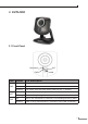
3. OUTLOOK 3.1 Front Panel ACT Microphone PWR LED PWR ACT LAN LAN Status LED Description Off No power. On Power on. Blinking The Power LED will blink during start up (15 ~ 20 sec). Off Camera is not capturing video. Blinking Camera is capturing video. Off LAN is not connected or camera is not sending/receiving data. Blinking Data is being transmitted or received via the LAN connection.
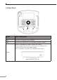
3.2 Rear Panel AUDIO OUT PWR LAN PORT PORT Description AUDIO OUT An external speaker can be plugged in. PWR Connect the supplied power adapter. LAN Connect your Camera to a 10/100Base-TX hub or switch. Reset to manufacturer default valued and reboot. When pressed and held over 10 seconds, the settings of IP Camera will be set to the default values. Upon completion, the PWE LED will blink three times.
4. Physical Installation 1. Connect an Ethernet cable Connect one end of an Ethernet cable to the LAN port located on the IP camera’s rear panel and connect the other end to the network device (hub or switch). 2. Attach the external power supply Attach the provided power adapter to the IP camera’s connector labeled “PWR” on the rear panel. 3. Check the LEDs a. The Power LED will turn on briefly, and then start blinking during startup. After startup is completed, the Power LED will remain ON. b.
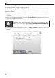
5. Setup Wizard Configuration Initial setup should be performed by using the supplied Windows-based Setup Wizard as follows: 1. Insert the bundled Product CD disk into CD-ROM drive to launch the autorun program. 2. After the web page displayed, click the “Setup Wizard” hyperlink on the list to start the configuration process. Note If the web page does not appear, click “Start” on the task bar and select “Run” to type “X:\Utility\SetupWizard\SetupWizard. exe”, assume X is your CD-Rom drive. 3.
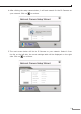
4. After clicking the setup camera button, it will auto search for the IP Cameras on your network. Click on to continue. 5. The next screen below will list the IP Camera on your network. Select it from the list on the left side, the current settings table will be displayed on the right side. Click on to continue.
6. The administrator login window will pop up. If the Administrator Name and Administrator Password have been set, you will be prompted to enter them. If using the default values, please enter “admin” for both the name and the password. Click on “OK” to continue. 7. On the following Camera Settings screen, you can fill and configure the Device Name, Description, Time Zone, Local Date and time here. Click on to continue.
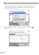
8. You can choose “Fixed IP Address” or “Dynamic IP Address” here. Click on to continue. Note 1. Fixed IP Address is recommended, and can always be used. 2. Dynamic IP Address can only be used if your LAN has a DCHP Server. 9. If you chose to use Fixed IP Address, the following TCP/IP Settings screen will be displayed. You can configure the IP Address, Subnet Mask, Default Gateway, Primary and secondary DNS. Click on to continue.
10. The next screen below will display all details of the IP Camera. Click on to continue if those settings are correct, or click on back to modify any incorrect values. 11. In this confirmation window below, click on “OK” to confirm that you want to save the new settings. If you want to cancel your changes, please click on “Cancel”.
12. After confirming, the wizard will start to save the new settings as below screen. 13. When the saving process is completed, the prompt window will be displayed as below screen. Click on “OK” to finish.
. The setup wizard now is completed. Click on “Exit” to close the setup wizard. After modifications, you may now connect the IP camera with the new configuration via web browser.
6. Cam Viewer Lite Installation Note The Cam Viewer Lite / Pro 30 days trial version installation steps are similar. Below is the installation of Cam Viewer Lite. 1. Insert the bundled Cam Viewer CD disk into the CD-ROM drive to launch the autorun program. Once completed, a welcome menu screen will appear. Click the “Cam Viewer Lite” hyperlink, the below InstallShield Wizard dialog box will appear. Note If the welcome screen does not appear, click “Start” at the taskbar.
3. The “Welcome to the InstallShield Wizard for Planet Cam Viewer Lite 1.0.3” will display on the screen, please click “Next”. 4.
5. Please key in user name and company name for which you want and click “Next” to continue installation. 6. Check the option “Complete”, all program features will be installed (Requires the most disk space) and click “Next” to continue installation.
7. “Ready to Install the Program” will appear to prompt you to start the installation. Please click “Install” to start. 8. Please click “No” to finish the Cam Viewer Lite installation. Note 18 In above step, when Cam Viewer works with MBM5 (Motherboard Monitor 5), Cam Viewer will display CPU temperature and fan speed. Please click “Yes” if you need this function and refer to the manual of Cam Viewer CD disk for complete installation.
Appendix A: Feature Listing for Cam Viewer Software Version Cam Viewer Lite Cam Viewer Pro IP Camera Input 32 4 / 8 / 16 / 32 / 64 - V Smart Guard - V I/O Device V V Hotline - V Address Book - V Unusual event System log Unusual event System log Counting application - 2 way counting Dual Monitor Log Viewer Counting Application Remote Playback Server Concurrent Playback Counting Function Smart Search Remote Live Viewer - Unlimited 1 Channel 16 Channels - V General Motion Gen
Appendix B: Suggest Hardware / System Requirement Total FPS CPU RAM Chipset of Motherboard ~600 600~480 480~240 240~120 120~ Intel Core 2 Duo QX6800 Intel Core 2 Duo E6600 Intel Pentium D 930 Intel P4 3.0 Intel P4 2.8 4 GB 2 GB 2 GB 1 GB 1 GB Intel 946 or 965 chip, Intel Chipset recommended VGA Card ATI Radeon 9200, nVIDIA GeForce FX-5200, Intel 945/965 or above (ATI recommended) Ethernet 100Base-TX or Above, Gigabit LAN recommended Hard Disk 160 GB or above O.S.