Internet Camera ICA-500 User’s Manual
Copyright Copyright (C) 2004 PLANET Technology Corp. All rights reserved. The products and programs described in this User’s Manual are licensed products of PLANET Technology, This User’s Manual contains proprietary information protected by copyright, and this User’s Manual and all accompanying hardware, software, and documentation are copyrighted.
Table of Contents CHAPTER 1 INTRODUCTION.............................................................................................. 1 Overview ............................................................................................................................ 1 Physical Details .................................................................................................................. 3 Package Contents ........................................................................................
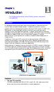
1 Chapter 1 Introduction This Chapter provides details of the ICA-500's features, components and capabilities. Overview As broadband communication gets more and more popular, it becomes easier to transfer video and audio through network. Traditional surveillance system is gradually evolving to be deployed in packet switching TCP/IP network. PLANET ICA500 provides an advanced digital solution of Internet Camera with pan and tilt capability to meet more application demands.
• Ease of use Plug-N-Watch capability to simplify system integration in an existing network environment • Meeting SOHO, business, or public facilities surveillance needs ICA-500 can be deployed in many different situations, such as library, train station or factory production line to provide efficient, human-resource reducing, and offers flexibility, affordability, and reliability for the proper surveillance of manufacturing facilities.
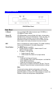
Physical Details ICA-500 Rear Panel Rear Panel LAN port Use a standard LAN cable to connect your ICA-500 to a 10/100BaseT hub or switch. Alarm I/O Connector ICA-500 provides a terminal block with 8 pins of connectors located on the center of the back panel. There are 3 pins for two alarm inputs and 5 pins are for alarm output. The I/O connectors are physical interface to sense and/or activate alarm signals to a variety of external sensors or alarms. MIC Built-in microphone for audio recording.
Package Contents The following items should be included: If any of these items are damaged or missing, please contact your dealer immediately.
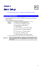
Chapter 2 Basic Setup 2 This Chapter provides details of installing and configuring the ICA-500. System Requirements • To use the LAN interface, a standard 10/100BaseT hub or switch and network cable is required.
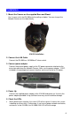
Installation 1. Mount the Camera on the supplied Base and Stand. Use 4 screws to fix the ICA-500 onto the ceiling as below. You can also put the Network Camera on the table directly. ICA-500 Installation 2. Connect the LAN Cable Connect the ICA-500 to a 10/100BaseT hub or switch. 3. Connect power adapter Connect the external power supply to the DC power connector attached on the extension cable from the Network Camera.
Setup Initial setup can be performed either from the web browser or using the supplied Windows-based camera utilities. This program can locate the ICA-500 even if its IP address is invalid for your network. You can then configure the ICA-500 with appropriate TCP/IP settings for your LAN. Subsequent administration can be performed with your Web browser, as explained in Chapter 3 - Web-based Administration.
• After modifications, you may now connect the camera via web browser.
Chapter 3 Advanced Viewing Setup 3 This Chapter provides information about the optional settings and features for viewing video via the ICA-500. This Chapter is for Administrators only. Introduction After finishing the network setup, the ICA-500 can immediately be used by all users on your LAN.
Camera setting 3. Make the required adjustments, as explained below, and save your changes. Video Settings Select the desired video resolution. The default resolution is set to 320*240. Resolution Available resolution: ‧176x144‧320x240‧352x288 ‧ 640x480 Image Quality Select the desired image quality. The default Image Quality is set to Standard.
11
Controlling User Access to the Video Stream By default, only system administrators can connect to the ICA-500 and view live Video. If desired, you may apply the access privileges to known users, by requiring each user to login to the ICA-500 with their individual username and password. To Enable this feature: 1. Connect to the Web-based interface of the ICA-500. (Please check related chapters for details.) 2. In machine Administration menu, select User. 3.
Making Video available from the Internet If your LAN is connected to the Internet, typically by a Broadband Gateway/Router and Broadband modem, you can make the ICA-500 available via the Internet. ICA-500 Setup The ICA-500 configuration does NOT have be changed, unless: • You wish to change the port number from the default value (1024). • You wish to use the DDNS (Dynamic DNS) feature of the ICA-500. Second HTTP Port Configuration Normally, HTTP (Web) connections use port 80.
DDNS (Dynamic DNS) Many Internet connections use a "Dynamic IP address", where the Internet IP address is allocated whenever the Internet connection is established. This means that other Internet users don't know the IP address, so can't establish a connection. DDNS is designed to solve this problem, by allowing users to connect to your LAN using a domain name, rather than an IP address. To use DDNS: 1. Register for the DDNS service with a supported DDNS service provider.
L Hint The "Port" for the Port Forwarding / Virtual Server entry above is the "Second Port" number specified on the Network screen of the ICA-500. Viewing via the Internet Clients (viewers) will need a broadband connection; dial-up connections are NOT recommended. Using your Web Browser If using your Web browser, you need to know the address of the camera (either the Internet IP address or the Domain name) and the correct communication port number.
You can then select the camera in the Cameras list on the main screen, and click OK to establish a connection and view live video. Please check respective chapter for further details of viewing Video using either the Windows Viewing/Recording utility or Web Browser.
Chapter 4 Web-based Management 4 This Chapter provides Setup details of the ICA-500’s Web-based Interface. This Chapter is for Administrators only. Introduction The ICA-500 can be configured using your Web Browser. The ICA-500 must have an IP address, which is compatible with your PC. Connecting to ICA-500 • If you have run the CamView utility, the screen provided a button this button will immediately connect to the ICA-500.
Welcome Screen When you connect, the camera Home screen will be displayed. Camera Home Screen The Home screen can be divided into three areas: • Viewing Area - Images from the Network Camera • Control Panel Area - Network Camera Manipulation and image quality control • Advanced Configuration area - only available for administrator. Camera administrator can have full configuration in this menu. These options are explained in the following sections.
Viewing Area This screen is displayed when you log in machine Viewing Area Screen • The ICA-500 web page requires ActiveX control to display the video content. The ActiveX control must be downloaded from the camera and installed on your PC. • The security settings on the Internet Explorer must allow the ActiveX plug in to be functional.
Control Panel Screen When you connect, the camera control panel screen will be displayed.
be higher Standard: System default value Frame rate adjustment directly Adjust video frame rate via giving a number directly. 1, 5, 10, 15, 20, 25, 30 Audio On/Off Turn on/off audio output function. Note: The Microphone is located on the rear panel. You need to position the MIC hole face to the audio source to have better audio quality. Advanced Configuration Area The Advanced Configuration menu offers more features and camera control privileges to meet various application demands.
User Setup user name, password and login privilege IP Filter Setup legal IP address of user login (This function should be used with function “User” respectively) Event Define the event from Motion detection and sensors for security purpose System Screen After entering machine Home screen, click on the System menu, you will see a screen like the example below.
Camera Screen This screen is displayed when the Camera menu option is clicked. Note: please adjust carefully to have proper machine configurations. Camera Screen Data - Camera Screen Camera Settings Image Size Display resolution selection, supported resolution in ICA-500: ‧176x144 ‧ 352x288 ‧ 320x240 ‧ 640x480 Please check the available network upload bandwidth and carefully select the proper video resolution.
Saturation, Sharpness, Contrast, Hue Key in respective value for image adjustment. It is not required to adjust this value when the image is vivid. Camera Tour To use the camera tour function, user must preset some camera positions first. Select the “SET Tour” button to enter the Camera Tour setting page. Reset to Default Restore the values of these pages to factory default value. Camera Tour In the Camera Tour page, choose the one tour name.
Network Screen This screen is displayed configure Network setting such as IP address, DHCP, DDNS and PPPoE. Network screen Data - Network Screen Network Settings DHCP Enable or disable DHCP client in ICA-500 IP address, Subnet mask, Default gateway, Primary DNS, Secondary DNS This parameter allows users to setup the IP address assigned by ISP. Your ISP should provide all the information requied for Internet access.
DDNS screen Network Settings Enable DDNS Enable or disable DDNS function. Username, Password Enter the Username/Password for your DDNS account. Domain Name Enter the host name, which DDNS service provider assigned. HTTP Proxy, Proxy Username, Proxy Password Enter the parameter, which DDNS service provider assigned.
PPPoE screen L Hint Please consult your ISP personnel to obtain proper PPPoE/IP address related information, and input carefully. If Internet connection cannot be established, please check the physical connection or contact the ISP service staff for support information.
User Screen This User setting can set up to 10 different usernames and passwords. Every one set of username and password can be acted as an Administrator or just a general user. User Screen IP Filter Screen The IP filter can set 10 different user’s IP address, which are allowing enter or disregarding by the Network Camera. Please configure “User” before “IP Filter”. Each “User” username and password matches with one “IP Filter” user.
Event Screen This is start two different sensors and motion detection for security purpose. If any motion detected or sensor has been activated, the Network Camera can issue a message or send a mail out to the person whose mail is assigned within SMTP.
Motion Detection Setup motion detection area and sensor sensitivity Time Setting Setup the Network Camera time configuration Popup Setup event message while motion or sensors has been activated Firmware Upgrade Product firmware upgrade Factory Default Pre-default the Network Camera factory default setting FTP Client Screen FTP Client Screen Network Settings FTP server name IP address or domain name of the destination FTP server Username, Password Please input the Username/Password for the FTP
Image file name Please input the basic file name you want to assign to the images when sending to the FTP server. Suffix Select the suffix to add to the file name. Sequence No. clear Enable or disable clear sequence number Mode Event / Periodical sending / Off Please select send a captured image mode.
SMTP Screen This screen is displayed when the SMTP menu option is clicked. SMTP (Simple Mail Transfer Protocol) is a protocol for sending e-mail messages between servers. The mail server address must be filled in this field. SMTP Screen Network Settings SMTP server name Enter the address of SMTP server used to send the mail. Please ensure the server is using SMTP protocol and able to relay mails for you. Some SMTP server may require authentication.
Alarm 1 & Alarm 2 Screen This screen is displayed when the Alarm 1/Alarm 2 menu option is clicked. You can select Manual or Event for the Alarm mode. Alarm1 Screen Alarm2 Screen Motion Detection Screen This screen is displayed when the Motion Detection menu option is clicked.
Network Settings Enable Motion Detection Enable or disable Motion Detection function in ICA-500 Sensitivity Select the desired option to suit your environment. If covering a large area, you usually need higher sensitivity, since a moving object will take only a small portion of the image.
Time Setting Screen This screen is displayed when the Time Setting menu option is clicked. Time Screen Network Settings IP Cam Time Provides settings of adjusting the camera’s time PC Time This is default time value for PC. Set Time Three options of Synchronize with PC's time / User Input / NTP are available for your selection to link with the Time Server.
Popup Screen This screen is displayed setting event message while motion or sensors has been activated When any one of alarms enabled, and one of them detected, then a message window will be displayed on the screen. Pop up Screen Network Settings Pop-up text Input the warming text. Display mode Select display mode for your Enable or disable the display of a text string in the video image. Type the text string that you want to display in the adjacent field.
Firmware upgrade Screen This screen is displayed when you click the Firmware Upgrade menu on the Status screen. Firmware Upgrade Screen This screen allows you upgrade the Firmware (software) in your ICA-500. Before using this screen, your must download the upgrade file to your PC. Then follow this procedure: 1. Click the Browse button, and locate the upgrade file. 2. Select this file, and click OK. The filename will then appear in the Upgrade File field. 3.
6. The upgrade progress status information will be displayed on the screen. Once the upgrading process completed, the Network Camera will reboot the system automatically. L Hint Do not interrupt the upgrading procedure during proceeding; or the inner component might be permanently damaged. Factory Default Screen This screen is displayed when you click the Factory Default menu on the Status screen. Please Click “OK” button to load default settings to camera.
Network Settings FTP Upload a captured image to server Mail Mail captured image to specific mail address Alarm 1 Enable Alarm output 1 Alarm 2 Enable Alarm output 2 Clear Alarm Clear both alarm output status Capture: This screen is displayed when you click the Capture menu and the function can capture current image and save it to storage media. The image is saved in the JPEG format.
ActiveX Control This feature only supports on the ActiveX control within Microsoft® Internet Explorer. View This screen is displayed when you click the “View” menu on the ActiveX control. View Settings Resizable Actual size Status Bar Make the image is resizable, but “Actual size disable”, the “Splits” is supported on this mode. Make the image show as the actual size, the “Splits” function does not work on this mode. A status bar display on the button of the image.
Rotate & Quality & Resolution Rotate: An image can be rotated in predefined 180-degree increments. Quality: Available quality : ‧High (Default)‧Low. Resolution: Available resolution: ‧176x144‧320x240‧352x288 ‧640x480 Image Recording This screen is displayed when you click the “Image Recording” menu on the ActiveX control.
Save as JPEG: Select this option and click “Save as JPEG” for detailed configurations. The predefined schedule can be set by JPEG. During the JPGEG file recording, a red icon displays on lower right position of the image to indicate the AVI saving process. If want stop the recording, please press the “Stop Image Recording” to stop the save as JPEG process. Save as AVI: Select this option and click “Save as AVI” for detailed configurations. The pre-defined schedule can be set by AVI.
• Please select the “Save Current Picture As “ to save the current display image into the local PC. • Please input the saved ”file name”, and click “Save” button. • Please select the file to display the saved image by using any one of graph editing tools.
Chapter 5 Client UTILITY 5 INSTALLATION The CamView utility for ICA-500 is a powerful utility for video recording, viewing, and camera administrations. Please insert the user’s manual CD and start the CamView installation from the default page or manually browse the Utility folder in the CD to install the software: 5.1. CamView Installation • Run the “setup.exe” to start installation. A welcome message is shown as the following figure, and then hit the Next button to continue.
• Decide which directory to install the software.
• Decide the program group name. By default, just hit the Next button to continue. • Decide whether to create a desktop icon of the program. By default, just hit the Next button to continue.
• Ready to install. By default, just hit the Install button to start installation.
• Installing, wait for a moment. • Installation complete. Press Finish to launch the program. Otherwise, uncheck the check box to run the program later.
HOW TO USE After successfully installing the utility, this icon, Double click on it to launch the program. , will be added to the desktop.
5.2. CamView User Interface 5.2. 5.2. 5.2. 5.2. 5.2. 5.2. 5.2. 5.2. CamView main screen. 5.2. 5.2.1. Date and Time The current date and time of the computer are displayed here. 5.2.2. Viewer Screen CamView is able to monitor up to 16 Internet cameras. Users may choose different layout to monitor different sites. The available camera display modes are shown below: • Single: Only one viewer displays video. • 2 x 2: The screen is divided into 4 sub-screens.
5.2.6. Camera Zoom Here are two buttons to zoom in or zoom out on the image. Note: camera zoom feature is reserved for future PTZ model. 5.2.7. Camera Pan/Tilt Control Here are five buttons to move the camera to the up, down, left, right and home, respectively 5.2.8. Camera Selector and Recording Here are buttons to select cameras, and toggle buttons for recording. 5.2.9. Alert Message Here is a combo box to show alert messages. Ex: free space is almost exhausted. 5.3.
Figure 5.3.1. The Application Tab 5.3.2. Camera Settings As shown in Figure 5.3.2, users can set parameters of each camera. If the Restore button is pressed, the current setting modifications of the specified camera will be cleared and restore to the original. If the Apply button is pressed, the current setting modifications will be applied to the specified camera. Note that these modifications are not saved to the persistent storage like HD on the computer.
Figure 5.3.2. The Camera Tab 5.3.3. Scheduling As shown in Figure 5.3.3, users can schedule recording tasks. When you press the Add button, the editing task will be added to the schedule item list. When the Modify button is pressed, the specified task will be updated. If the Remove button is pressed, the specified task will be removed from the list. The Apply button is unused for this tab. Press OK button will save all settings on all tabs, and exit the form.
Figure 5.3.3. The Scheduling Tab 5.3.4. Application Settings Figure 5.3.4 shows settings for the global scope of the application including initialization and environment. After all settings are complete, press the OK button to save the configuration, and exit the form. The Apply button is unused for this tab. The following lists descriptions of each setting: • Alert Free Percentage (%): Set the percentage of free space you want to designate for alerts.
Figure 5.3.4. The Application Tab 5.4. Camera Configuration Users can hit the button shown in Figure 5.4 to configure the specified camera. The configuration guide is not included in the document. Please read the documentation of the camera. Figure 5.4. 5.5. Recording There are three methods to start recording. The first is to press the toggle button as shown in Figure 5.5-1 to start recording for the camera specified by the selector combo box on the right-top side of the panel.
Figure 5.51 Figure 5.53 Figure 5.52 Figure 5.54 5.6. Playback When you press the Playback button on the panel as shown in Figure 5.6, a form will appear to show the list of video records and snapshots. Figure 5.6. 5.6.1. Video List The video list tab lists video records, and displays the information about the specified record. When you hit the Play button, the Windows Media Player will start to play the video. The Video list is shown in the following figure. Figure 5.6.1. The Video List Tab 5.6.2.
Figure 5.6.2. The Snapshot List Tab 5.6.3. Video Search The video search tab lists video file information about the specified search. When you enter the search qualification, then hit the Search button, you will get the matched video files. Select an item, hit the Play button, Windows Media Player will be opened to play the video. It is shown in the following figure. Figure 5.6.3.
5.7. Image Rotation After the button is pressed, the display image rotates 180 degree. It is used for the camera being installed upside-down direction. Note video/images in recorded video will not be rotated. Figure 5.7. 5.8. eMap When you press the eMap button on the panel as shown in Figure 5.8, a form will appear to show the eMap function. Figure 5.8. 5.8.1. eMap Setting Select the File from the menu bar and follow these steps to set up eMap : 1.New Layout: First, create a new layout. 2.
Figure 5.8.1. Layout example 1 Figure 5.8.2.
• When your mouse moves over the camera icon, you can click the right button to display a menu which has options to set the configuration, show the record list, record, show video and remove the camera icon. Figure 5.8.3.
Appendix A: Alarm I/O Connector The terminal block is used in applications for e.g. motion detection, event triggering, time lapse recording, alarm notification via email, image storage to FTP locations, etc. ICA-500 provides a general I/O terminal block with two digital inputs and two outputs for device control. Pin 1 and 2 can be connected to an external sensor 1. Pin 2 and 3 can be connected to an external sensor 2. Both of the inputs, the voltage will be monitored from the initial state ‘LOW’.
Appendix B: Troubleshooting Q: The video and audio codec is adopted in the Network Camera? A: The Network Camera utilizes JPEG compression to providing high quality images. JPEG is a standard for image compression and can be applied to various web browsers without the need to install extra software. The audio codec is ADPCM compression. Q: The maximum number of users access Network Camera simultaneously.
assigned to the PC properly. • Antivirus software on the PC might interfere with the setup program. Disable the firewall of the antivirus software during setting up ICA-500. Q: Internet Explorer does not seem to work well with the ICA-500 A: Make sure that your Internet Explorer is version 6.0 or later. If you are experiencing problems, try upgrading to the latest version of Microsoft’s Internet Explorer from the Microsoft webpage at: http://www.microsoft.com/windows/ie.
Q: Check the ICA-500’s ActiveX is installed on your computer A: Go to C:\Windows\Downloaded Program Files and check to see if there is an entry for the file “WebWatch Class”. The status column should show “Installed”. If the file is not listed, make sure your Security Settings in Internet Explorer are configured properly and then try reloading the ICA-500’s home page. Most likely, the ICA-500 ActiveX control did not download and install correctly.
A: • To insure the images you are viewing are the best they can be, set the Display property setting (color quality) to 16bit at least and 24 bit or higher if possible within your computer. •The configuration on the ICA-500 image display is incorrect. You need to adjust the image related parameters such as brightness, contrast, hue and saturation properly. Q: Image flickers A: ‧ Wrong power line frequency makes images flicker. Make sure the NTSC or PAL format of your ICA-500 .
Appendix C: Bandwidth Calculation The frame rate of video transmitted from the ICA-500 depends on connection bandwidth between client and server and quality setting of server. Here is a guideline to help you roughly estimate the bandwidth requirements form your ICA-500. Image bandwidth is approximately equal to the average frame rate in frames per second multiplied by the average frame data size in kilobits.
Appendix D: Specifications Model Hardware Sensor Iris control Gain control White balance Focus Minimum Illumination PAN (Horizontal Rotation) Tilt (Vertical Rotation) Network ICA-500 1/3” CCD sensor Video-drive iris control High/Low switchable Indoor, auto mode (color temperature: 2500K~9000K) Fixed, lens length=3.6mm, manually fine tune 0.2LUX@F2.