
Quick Guide


6
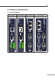
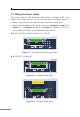
3.2 Wiring the Power Inputs
The upper panel of the Industrial Serial Server indicates a DC inlet
power socket and consists of one terminal block connector within 6
contacts. Please follow the steps below to insert the power wire.
1. Insert positive/negative DC power wires into Contacts 1 and 2 for
Power 1, or Contacts 5 and 6 for Power 2. Figures 3-1 to 3-3
show PWR1 and PWR2 of the Industrial Serial Server.
ICS-2100T/ICS-2105AT: 9~48V DC or 24V AC
V1+ V2+ V2
PWR1 PWR2Fault
Max. fault loading: 24V, 1A
DC Input: 9-48V
, 1A max.
AC Input: 24V
, 0.5A max.
1 2 3 4 5 6
Figure 3-1: ICS-2100T/ICS-2105AT Upper Panel
ICS-2200T: 12~48V DC
V1+ V1- V2+ V2-
PWR1
PWR2Fault
DC Input:
12-48V , 1Amax.
1 2 3 4 5 6
Figure 3-2: ICS-2200T Upper Panel
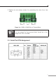
1A@24V
V1+ V1- V2+ V2-
PWR1
PWR2Fault
DI1 DO0 DO1DI0 GNDGND
DC Input:
12-48V , 1Amax.
1 2 3 4 5 6
1 2 3 4 5 6
Figure 3-3: ICS-2400T Upper Panel