
IFT-80x Series User Manual
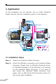


21
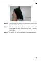
Step 3: To hang the Industrial Media Converter on the DIN-
Rail track or wall, please refer to the Mounting
Installation section.
Step 4: Power on the Industrial Media Converter. (Please
refer to the Wiring the Power Inputs section for
power input) The power LED on the Industrial Media
Converter will light up. Please refer to the LED
Indicators section for meaning of LED lights.
Step 5: Prepare the twisted-pair, straight through Category 5
cable for Ethernet connection.
Step 6: Insert one side of Category 5 cables into the
Industrial Media Converter Ethernet port (RJ-45
port) and another side of category 5 cables to the
network devices' Ethernet port (RJ-45 port), ex:
Switch, PC or Server. The UTP port (RJ-45) LED on
the Industrial Media Converter will light up when the
cable connected with the network device. Please refer
to the LED Indicators section for LED light meaning.
Note
Be sure the connected network devices support
MDI/MDI-X. If it does not support then use the
crossover category 5 Cable.
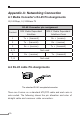
Step 7: Insert ber cable from the IFT-802T / 802TS15 /
805AT to the ber network. TX, RX must be paired
at both ends. The optical port LED on the Industrial
Media Converter will light up when the cable
connected with the network device. Please refer to
the LED Indicators section for LED light meaning.
Step 8: When all connections are all set and LED lights all
show in normal, the installation is complete.