User’s Manual of IMG-110T Trademarks Copyright PLANET Technology Corp. 2017. Contents are subject to change without prior notice. PLANET is a registered trademark of PLANET Technology Corp. All other trademarks belong to their respective owners.
User’s Manual of IMG-110T TABLE OF CONTENTS 1. INTRODUCTION ............................................................................................................. 5 1.1 PACKAGE CONTENTS .................................................................................................................................. 5 1.2 HOW TO USE THIS MANUAL ......................................................................................................................... 5 1.3 PRODUCT DESCRIPTION ..........
User’s Manual of IMG-110T 4.6.1 COM State ........................................................................................................................................................ 58 4.7 ACCESS CONTROL .................................................................................................................................... 59 4.7.1 Device Security ........................................................................................................................................
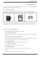
User’s Manual of IMG-110T 1. INTRODUCTION Thank you for purchasing PLANET Industrial 1-port RS422/485 Modbus Gateway, IMG-110T. The term “Industrial Modbus Gateway” mentioned in this user’s manual refers to the IMG-110T. 1.1 Package Contents Open the box of the Industrial Modbus Gateway and carefully unpack it.
User’s Manual of IMG-110T 1.3 Product Description Economic Solution for Industrial Modbus TCP/RTU/ASCII Network Integration PLANET has added the Industrial Modbus TCP/IP Protocol to industrial management level products to provide its easily-integrated industrial management level products with SCADA/HMI system and other data acquisition systems in factory floors. Moreover, the industrial IT SNMP network is upgraded to the industrial automation Modbus TCP/IP network.
User’s Manual of IMG-110T Stable Performance in Hardened Environment Design The Industrial Modbus Gateway provides a high level of immunity against electromagnetic interference and heavy electrical surges which are usually found on plant floors or in curb-side traffic control cabinets. Its operating temperature ranging from -40 to 75 degrees C allows the Industrial Modbus Gateway to be placed in almost any difficult environment.
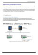
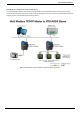
User’s Manual of IMG-110T Multi Modbus TCP/IP Master to RTU/ASCII Slaves The Industrial Modbus Gateway can operate as a bridge between the multi-industrial TCP/IP master equipment and the industrial RTU/ASCII slave equipment in a Modbus TCP/IP networking environment to control the industrial RTU/ASCII slave equipment via the multi-industrial TCP/IP master equipment.
User’s Manual of IMG-110T 1.5 Product Features Serial Interface ■ One RS422/485 port with 5-contact terminal block ■ Cost effective for RS422/RS485 to Fast Ethernet 10/100BASE-TX application ■ Supports 4-wire RS422 or 2-wire RS485 with 5-contact terminal block operation ■ 300bps~115200bps baud rate and non-blocking communication Ethernet Interface ■ Complies with IEEE 802.3, IEEE 802.
User’s Manual of IMG-110T 1.
User’s Manual of IMG-110T Installation Wall-mount kit Mechanical Metal Management Remote Web Management Management Remote Telnet Management PLANET Modbus Gateway Utility PLANET Smart Discovery Utility RTU Master Operation Mode RTU Slave ASCII Master ASCII Slave Standards Conformance IEEE 802.310BASE-T standard Standards Compliance IEEE 802.3u 100BASE-TX standard IEEE 802.
User’s Manual of IMG-110T 2. HARDWARE INSTALLATION This section describes the hardware features and installation of the Industrial Modbus Gateway’s components on the desktop or shelf. For easier management and control of the Industrial Modbus Gateway, familiarize yourself with its display indicators, and ports. Front panel illustrations in this chapter display the unit LED indicators. Before connecting any network device to the Industrial Serial Converter, please read this chapter completely. 2.
User’s Manual of IMG-110T Figure 2-2 shows the front panel of the Industrial Modbus Gateway. Figure 2-2: Industrial Modbus Gateway Front Panel 2.1.2 LED Indicators ■ LED Definition ■ System LED Color Power Green Function Lights to indicate the system has power. ■ 10/100BASE-TX Interface LED Color LNK/ACT Green Function Lights: To indicate the link through that port is successfully established. Blinks: To indicate that the IMG-110T is actively sending or receiving data over that port.
User’s Manual of IMG-110T 2.1.3 2-Contact Terminal Block Pin Define ■ Wiring the Power Inputs: The 2-contact terminal block connector on the top panel of the Industrial Modbus Gateway is used for DC power input and the DC power input range is 9-48V. 1: Please follow the DC power input symbol on the front panel of the Industrial Modbus Gateway -- insert positive DC power wire into V+, and negative DC power wire into V-. Otherwise, it will damage the device.
User’s Manual of IMG-110T 2.1.5 Hardware DIP Switch for Reset to Default The upper panel of the Industrial Modbus Gateway consists one 4-bit DIP switch for resetting the system to the factory default mode. ■ Resetting to default through hardware DIP switch: 1: Find the hardware DIP switch that is near the RJ45 port of the Industrial Modbus Gateway. 2: Adjust DIP 2 at the “ON” position and DIPs 1, 3, 4 remain at the original position.
User’s Manual of IMG-110T 3. INDUSTRIAL MODBUS GATEWAY MANAGEMENT This chapter describes how to manage the Industrial Modbus Gateway. Sections include: - Overview -Requirements - Management Methods - PLANET Smart Discovery Utility - PLANET Modbus Gateway Utility 3.1 Overview This chapter gives an overview of the Industrial Modbus Gateway management. The Industrial Modbus Gateway provides a remote IP-based WEB browser/Telnet interface.
User’s Manual of IMG-110T 3.2 Requirements ■ Ethernet Port Connection • Workstations running Windows XP/2003/Vista/7/8/2008/10, MAC OS X or later, Linux, UNIX, or other platforms are compatible with TCP/IP protocols. • Workstations are installed with Ethernet NIC (Network Interface Card) Network cables -- Use standard network (UTP) cables with RJ45 connectors. The above PC is installed with Web browser and JAVA runtime environment plug-in. It is recommended to use Internet Explorer 8.
User’s Manual of IMG-110T 3.3.2 Login the Industrial Modbus Gateway Web Interface The following shows how to start up the Web Management of the Industrial Modbus Gateway. Note the Industrial Modbus Gateway is configured through an Ethernet connection. Please make sure the manager PC must be set to the same IP subnet address. For example, the default IP address of the Industrial Modbus Gateway is 192.168.0.100, then the manager PC should be set to 192.168.0.
User’s Manual of IMG-110T Figure 3-5: Web Main Screen of Industrial Modbus Gateway For security reason, please change and memorize the new password after this first setup. 1. Only accept command in lowercase letter under web interface. 3.3.3 Remote IP-based Telnet Interface The Industrial Modbus Gateway offers management features that allow users to manage the Industrial Modbus Gateway from anywhere on the network through remote IP-based telnet interface.
User’s Manual of IMG-110T 3.3.4 Login the Industrial Modbus Gateway Telnet Interface The following shows how to start up the Telnet Management of the Industrial Modbus Gateway. Note the Industrial Modbus Gateway is configured through an Ethernet connection. Please make sure the manager PC must be set to the same IP subnet address. For example, the default IP address of the Industrial Modbus Gateway is 192.168.0.100, then the manager PC should be set to 192.168.0.
User’s Manual of IMG-110T 3.4 PLANET Smart Discovery Utility For easily listing the Industrial Modbus Gateway in your Ethernet environment, the Planet Smart Discovery Utility is an ideal solution. The following installation instructions are to guide you to running the Planet Smart Discovery Utility. 1. Insert the attached user’s manual CD in the CD-ROM Drive. 2. Find and deposit the Planet Smart Discovery Utility in administrator PC. 3. Run this utility as the following screen appears.
User’s Manual of IMG-110T 1. This utility shows all necessary information from the devices, such as MAC address, device name, firmware version and device IP subnet address. It can also assign a new password, IP subnet address and description for the devices. 2. After the setup is completed, press the “Update Device”, “Update Multi” or “Update All” button to take effect. The functions of the 3 buttons above are shown below: Update Device: Use the current setting on one single device.
User’s Manual of IMG-110T 3.5 PLANET Modbus Gateway Utility For easily listing and manage the Industrial Modbus Gateway in your Ethernet environment, the Planet Modbus Gateway Utility is an ideal solution. The following installation instructions are to guide you to installing and running the Planet Modbus Gateway Utility. 3.5.1 Installing PLANET Modbus Gateway Utility The following install instructions guide you to the installations of the Planet Modbus Gateway Utility. 1.
User’s Manual of IMG-110T Figure 3-12: Planet Modbus Gateway Utility Install Process Screen Figure 3-13: Planet Modbus Gateway Utility Install Process Screen -24-
User’s Manual of IMG-110T Figure 3-14: Planet Modbus Gateway Utility Install Process Screen Figure 3-15: Planet Modbus Gateway Utility Install Process Screen -25-
User’s Manual of IMG-110T Figure 3-16: Planet Modbus Gateway Utility Install Process Screen Figure 3-17: Planet Modbus Gateway Utility Install Complete Screen -26-
User’s Manual of IMG-110T 4. Find the PLANET Modbus Gateway UtilityV1.0 icon on the desktop of administrator PC and double-click it as the icon is shown below: 5. After the installation is completed, execute the utility. The screen in Figure 3-18 appears.
User’s Manual of IMG-110T 3.5.2 PLANET Modbus Gateway Utility Menu Bar The Planet Modbus Gateway Utility menu bar has the following options: - System(S) - Tools(Y) Figure 3-19: Planet Modbus Gateway Utility Tool Bar Screen 3.5.2.1 System(S) This function provides Select network adapter and Quit for closing the PLANET Modbus Gateway Utility.
User’s Manual of IMG-110T 3.5.2.2 Tools(Y) This function provides the following options: - Search Device - Set Search Type - Set Timing Save - Manual Add Device - Batch IP Settings (B) Figure 3-23: Planet Modbus Gateway Utility Tool Bar -- Tools Screen Search Device This option allows you to search the connected Industrial Modbus Gateway for further management .
User’s Manual of IMG-110T Set Search Type This option allows you to specify which equipment is used for further management; the available options are shown below: - Serial Server - Switch - All Figure 3-25: Planet Modbus Gateway Utility Tool Bar -- Set Search Type Screen The Switch option is a future feature which is not applicable at the moment. 1. Suggest choose the option of Serial Server or All for this function.
User’s Manual of IMG-110T Set Timing Save This option allows you to save timing device alert information to the database or specified file. Enable “True” for setting the timing save function. In the “Activation time”, set the cycle time of the save alarm information to “0H 30M 0S”, meaning it is saved every 30 minutes. In “Type”, select “Saved to the database” or “Saved to the TXT file”. When selecting “Saved to the database”, it is saved in “alert log query”.
User’s Manual of IMG-110T Manual Add Device This option allows you to manually set up IP search device and send search unicast packets; there are two ways to manually add the device as shown below: 1: Add "On line Devices" under an existing IP address, click "√" in front of the desired IP address and click on ">" to add IP address; 2: A "Device IP Address" is filled out to manually enter the IP address and click "Add" to add the IP address. Click OK for adding a unicast packet to search equipment.
User’s Manual of IMG-110T Batch IP Settings This option allows you to set up IP addresses for a group of devices so as to avoid one-by-one setting, which can save a lot of time. Figure 3-28: Planet Modbus Gateway Utility Tool Bar -- Batch IP Settings Screen The IP address range is 1-254.
User’s Manual of IMG-110T 3.5.3 PLANET Modbus Gateway Utility Shortcut Menu Bar The Planet Modbus Gateway Utility shortcut menu bar has the following options: - User Manager - Import Network Topology -Export Network Topology -Zoom In -Zoom Out -Search Device -Save Topology -Delete Topology -Batch IP Settings -Batch Monitoring IP Settings -Hide Device Tree -Hide Alarm List -Auto Refresh Topology -Refresh Interval Figure 3-29: Planet Modbus Gateway Utility Shortcut Menu Bar Screen 3.5.3.
User’s Manual of IMG-110T The page includes the following fields: Object Description • New Name The ID of the user. Maximum length: 18 characters. • Password Enter the user’s new password here. Maximum length: 18 characters. • Confirm Password Please enter the user’s new password here again to confirm. Button : Click to apply changes. Please remember the newly set-up “user name” and “password”; in case the user name and password are forgotten, please re-install the PLANET Modbus Gateway Utility.
User’s Manual of IMG-110T 3.5.3.6 Search Device : This option allows you to search the connected Industrial Modbus Gateway for further management . Figure 3-31: Planet Modbus Gateway Utility Shortcut Menu Bar -- Search Device Screen 3.5.3.7 Save Topology : This option allows you to change the topology and save it in Industrial Modbus Gateway Utility. 3.5.3.8 Delete Topology : This option allow to delete the change of topology and save it in Industrial Modbus Gateway Utility. 3.5.3.
User’s Manual of IMG-110T 3.5.3.10 Batch Monitoring IP Settings : This option allows you to set up Batch Monitoring IP addresses for a group of devices. Figure 3-33: Planet Modbus Gateway Utility Shortcut Menu Bar -- Batch Monitoring IP Settings Screen Button : Click to apply changes. 3.5.3.11 Hide Device Tree/Show Device Tree : This option allows you to hide or show the device tree in Industrial Modbus Gateway Utility. 3.5.3.
User’s Manual of IMG-110T 3.5.4 PLANET Modbus Gateway Utility Device Function The Planet Modbus Gateway Utility provides the following options for Industrial Modbus Gateway device management. - Web Console - Device Name -Network Settings -Reset Factory Settings -Recent Alarm 3.5.4.1 Web Console This function provides Web interface access to PLANET Modbus Gateway.
User’s Manual of IMG-110T 3.5.4.2 Device Name This function is to change the Device name and Device number of PLANET Modbus Gateway. Figure 3-35: Planet Modbus Gateway Utility Device Function -- Device Name Screen Button : Click to apply changes. 3.5.4.3 Network Settings This function is to change the IP subnet address of PLANET Modbus Gateway. Figure 3-36: Planet Modbus Gateway Utility Device Function -- Network Settings Screen Button : Click to apply changes.
User’s Manual of IMG-110T 3.5.4.4 Reset Factory Settings This function is to reset PLANET Modbus Gateway to default as the procedure is shown below: Step 1: Activate PLANET Modbus Gateway Utility. Step 2: Search the Industrial Modbus Gateway that needs to be reset to default and choose the device. Step 3: Right-click to choose the “Restore Factory Settings”.
User’s Manual of IMG-110T Figure 3-39: Planet Modbus Gateway Utility Device Function -- Restore Factory Settings Screen Button : Click to apply changes. Step 6: Search the device again and you will see the Industrial Modbus Gateway with default IP address, and username and password: “admin”.
User’s Manual of IMG-110T 3.5.4.5 Recent Alarm This function is to display the alarm information of PLANET Modbus Gateway and also save the alarm messages for further review or export the alarm message as an excel file. The three options for the alarm message are shown below: -Clear-clear alarm messages. -Save-save alarm messages. -Query-alarm log export.
User’s Manual of IMG-110T 4. WEB MANAGEMENT The Industrial Modbus Gateway provides Web interface for management function configuration which makes the Industrial Modbus Gateway operate more effectively. It can be configured through the various web browser tools. A network administrator can manage and monitor the Industrial Modbus Gateway from the local LAN. This section indicates how to configure the Industrial Modbus Gateway to enable its management to function. 4.
User’s Manual of IMG-110T Access Control Configure access control parameters as shown below: Device Security: allow disable or enable Web Console, Telnet Console, Device Search, Firmware Upgrade function. IP Filtering: set up the IP address filtering function. MAC Filtering: set up the MAC address filtering function. System Management User Management: allow to modify the username and password or disable authentication function. 3 sets of username and password can be configured.
User’s Manual of IMG-110T • Description The description of Industrial Modbus Gateway. • Contact The contact information of Industrial Modbus Gateway. • Serial No. The serial number information of Industrial Modbus Gateway. • Number of LANs The number of LANs information of Industrial Modbus Gateway. Network Information • IP Mode The current IP operation mode of Industrial Modbus Gateway. • IP Address The current IP Address of the Industrial Modbus Gateway.
User’s Manual of IMG-110T The page includes the following configurable data: Network Settings • Use the following IP Address Choose static IP address for the Industrial Modbus Gateway. • Automatically Obtain IP Address Enable the DHCP function for the Industrial Modbus Gateway. When enabling this function, the Industrial Modbus Gateway will send a DHCP request to the DHCP server in the network.
User’s Manual of IMG-110T 4.4 Serial Settings This function provides serial port COM settings and displays the serial port COM information. 4.4.1 COM Settings This function allows setting the value for serial port COM configuration. Press the “Submit” button to set the value and the screen in Figure 4-4 appears. Figure 4-4: Serial Settings -- COM Settings Screen The page includes the following configurable data: Port Setting • Port Display the COM1 information.
User’s Manual of IMG-110T • Parity Bits It is a simple method to check out fault in serial communication; it has 4 types: Even/Odd/Mark/Space. • Flow Control Flow control is determined by product hardware. For some reason, it cannot communicate. When communication is blocked, open the flow control to ease. Flow control allows the data receiving device to notify the data sending device when it is unable to receive the data, so that it can be stopped. It includes XON/XOFF,DTR/DSR, and RTS/CTS.
User’s Manual of IMG-110T 4.4.2 COM Information The function displays the serial port COM information like the current communication parameters of serial port as shown below: -Port -Alias -Baud Rate -Data Bits -Stop Bits -Parity Bits -Flow Control -FIFO -Work Mode The screen in Figure 4-5 appears.
User’s Manual of IMG-110T 4.5 Modbus Settings This function provides Modbus parameters settings and slave ID settings. 4.5.1 Modbus Parameters This function allows setting the value for serial port COM configuration. Press the “Submit” button to set the value and the screen in Figure 4-4 appears.
User’s Manual of IMG-110T • Inter-character Timeout (0ms,10-500ms) In a single frame, the time difference is between a single character and the next character. When the value is 0, the default is 3.5T time, which is equal to 3.5 characters. The available range is 10-500ms. • Inter-frame Delay (0ms,10-500ms) The current RTU response with the next RTU request is between the time intervals. The default is 0ms. This feature is to avoid the RTU request from the station equipment.
User’s Manual of IMG-110T 4.5.2 Slave ID The Modbus protocol provides a unique ID number (1 ~ 247) to all of the slave devices. The ID number is used to identify the address of the slave device to respond to requests from the master device. The Modbus equipment ID number is set by the manufacturers. Most of them can be modified. It is an actual ID number. Virtual ID is used to specify the ID Modbus of each connected gateway.
User’s Manual of IMG-110T The page includes the following fields: Slave ID Map Table Display the channel number. Channel No. Channel Type Channel Definition Slave ID Range (Virtual~~~Real) This parameter is to choose RTU Master/RTU Slave/ASCII Master/ASCII Slave operation modes; the default mode is RTU Slave. Display the channel definition information. Display the Slave ID Range information. Provide Delete and Modify button. Operate to access the following parameters screen.
User’s Manual of IMG-110T RTU Master Mode This function allows the users to use Modbus RTU master device and Modbus TCP device to achieve communication. The operation mode of the Industrial Modbus Gateway is set to RTU Master. Step 1: Choose “RTU Master” in Channel Type. Step 2: Press the “Add” button to input the setting parameters. Step 3: After setup is completed, press the “Affirm” button to take effect.
User’s Manual of IMG-110T RTU Slave Mode This function allows the users to use Modbus TCP master device and Modbus RTU device to achieve communication. The operation mode of the Industrial Modbus Gateway is set to RTU Slave. Step 1: Choose” RTU Slave” in Channel Type. Step 2: Press the “Modify” button to input the setting parameters. Step 3: After setup is completed, press the “Affirm” button to take effect.
User’s Manual of IMG-110T ASCII Master Mode This function allows the users to use Modbus ASCII master device and Modbus TCP device to achieve communication. The operation mode of the Industrial Modbus Gateway is set to ASCII Master. Step 1: Choose “ASCII Master” in Channel Type. Step 2: Press the “Add” button to input the setting parameters. Step 3: After setup is completed, press the “Affirm” button to take effect.
User’s Manual of IMG-110T ASCII Slave Mode This function allows the users to use Modbus TCP master device and Modbus ASCII device to achieve communication. The operation mode of the gateway is set to ASCII Slave. Step 1: Choose “ASCII Slave” in Channel Type. Step 2: Press the “Modify” button to input the setting parameters. Step 3: After setup is completed, press the “Affirm” button to take effect. Figure 4-15: Slave ID Parameters Screen Figure 4-16: Slave ID-ASCII Slave Screen The virtual ID is 3~4.
User’s Manual of IMG-110T 4.6 State Monitoring This function provides Industrial Modbus Gateway serial COM port traffic counter in Transmit (TX) and Receive (RX). 4.6.1 COM State The function displays the serial port COM state information like the current traffic counter of serial port as the screen in Figure 4-17 appears. Figure 4-17: State Monitoring -- COM State Screen The page includes the following fields: Port Indicate the port number.
User’s Manual of IMG-110T 4.7 Access Control This function provides access control parameters of Industrial Modbus Gateway, including: -Device Security -IP Filtering -MAC Filtering -User Management 4.7.1 Device Security This function allows setting up the device security functions of Industrial Modbus Gateway. Press the “Submit” button to apply the setting as the screen in Figure 4-18 appears.
User’s Manual of IMG-110T 4.7.2 IP Filtering This function allows setting up the IP Filtering function of Industrial Modbus Gateway. Press the “Submit” button to apply the setting as the screen in Figure 4-19 appears. Figure 4-19: Access Control -- IP Filtering Screen The page includes the following configurable data: IP Filtering This function provides “Disable” or “Enable” the IP Filtering function. Filtering Rule This function provides “Allowed” or “Forbidden” options for the filtering rule.
User’s Manual of IMG-110T 4.7.3 MAC Filtering This function allows setting up the MAC Filtering function of Industrial Modbus Gateway. Press the “Submit” button to apply the setting as the screen in Figure 4-20 appears. Figure 4-20: Access Control -- MAC Filtering Screen The page includes the following configurable data: MAC Filtering This function provides “Disable” or “Enable” the MAC Filtering function. Filtering Rule This function provides “Allowed” or “Forbidden” options for the filtering rule.
User’s Manual of IMG-110T 4.7.4 User Management This function allows setting up the user management function of Industrial Modbus Gateway. Press the “Submit” button to apply the setting as the screen in Figure 4-21 appears. Figure 4-21: Access Control -- User Management Screen The page includes the following configurable data: Authentication This function provides “Disable” or “Enable” the authentication function. Number Indicate the number from 1 to 3 for user management items.
User’s Manual of IMG-110T 4.8 System Management This function provides access control parameters of Industrial Modbus Gateway, including: -System Information -System File -Logout & Reboot 4.8.1 System Information This function allows editing the system information of Industrial Modbus Gateway. Press the “Submit” button to apply the setting as the screen in Figure 4-22 appears.
User’s Manual of IMG-110T 4.8.2 System File This function allows setting up the factory default/Configuration backup and restore/web firmware upgrade functions of Industrial Modbus Gateway as the screen in Figure 4-23 appears. Figure 4-23: System Management-System File Screen The page includes the following configurable data: Factory Configuration Load Factory Default Press the “Start” button to start factory default process.
User’s Manual of IMG-110T 4.8.3 Logout & Reboot This function provides setting up system logout function and rebooting system function of Industrial Modbus Gateway as the screen in Figure 4-24 appears. Figure 4-24: System Management -- Logout & Reboot Screen The page includes the following configurable data: System Logout This function provides “System Logout” from web interface of Industrial Modbus Gateway. Press the “Start” button to log out the system.
User’s Manual of IMG-110T 5. COMMAND LINE INTERFACE 5.1 Accessing the CLI When accessing the management interface for the Industrial Modbus Gateway via a remote Telnet connection, the Industrial Modbus Gateway can be managed by entering command keywords and parameters at the prompt. Using the Industrial Modbus Gateway’s command line interface (CLI) is very similar to entering commands on an UNIX system.
User’s Manual of IMG-110T 6. COMMAND LINE MODE The CLI groups all the commands in appropriate modes according to the nature of the command. A sample of the CLI command modes are described below. Each of the command modes supports specific software commands. After logging in and accessing the Industrial Modbus Gateway Telnet interface, please enter “?” or “help” under Industrial Modbus Gateway Telnet interface where it displays a list of the available commands and descriptions of the commands.
User’s Manual of IMG-110T Manage This command will access system management menu. Information This command will access system information setup menu. Modbus This command will access Modbus setup menu. Command lines online help Description: Command lines port provides the following online help Total help Partial help Syntax: Total help Type in To get all commands and their description.
User’s Manual of IMG-110T History command Description: Command lines port can provide the function similar to Dos key. It automatically saves command lines that users type in, and users can use these history commands. Syntax: Operating Key Result Visit previous history command Up <↑> When existing earlier command, it is taken out. Visit next history command Down <↓> When existing later command, it is taken out.
User’s Manual of IMG-110T APPENDIX A A.1 Device‘s RJ45 Pin Assignments ■ 10/100Mbps, 10/100BASE-TX Contact 1 MDI 1 (TX +) MDI-X 3 2 2 (TX -) 6 3 3 (RX +) 1 6 6 (RX -) 2 4, 5, 7, 8 Not used Not used Implicit implementation of the crossover function within a twisted-pair cable, or at a wiring panel, while not expressly forbidden, is beyond the scope of this standard. A.