
User Manual
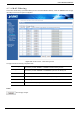
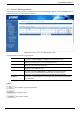
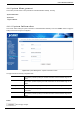


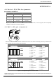
Table Of Contents
- 1. INTRODUCTION
- 2. HARDWARE INSTALLATION
- 3. INDUSTRIAL MODBUS GATEWAY MANAGEMENT
- 3.1 Overview
- 3.2 Requirements
- 3.3 Management Methods
- 3.4 PLANET Smart Discovery Utility
- 3.5 PLANET Modbus Gateway Utility
- 3.5.1 Installing PLANET Modbus Gateway Utility
- 3.5.2 PLANET Modbus Gateway Utility Menu Bar
- 3.5.3 PLANET Modbus Gateway Utility Shortcut Menu Bar
- 3.5.3.1 User Manager
- 3.5.3.2 Import Network Topology
- 3.5.3.3 Export Network Topology
- 3.5.3.4 Zoom In
- 3.5.3.5 Zoom Out
- 3.5.3.6 Search Device
- 3.5.3.7 Save Topology
- 3.5.3.8 Delete Topology
- 3.5.3.9 Batch IP Settings
- 3.5.3.10 Batch Monitoring IP Settings
- 3.5.3.11 Hide Device Tree/Show Device Tree
- 3.5.3.12 Hide Alarm List/Show Alarm List
- 3.5.3.13 Auto Refresh Topology
- 3.5.3.14 Refresh Interval
- 3.5.4 PLANET Modbus Gateway Utility Device Function
- 4. WEB MANAGEMENT
- 5. COMMAND LINE INTERFACE
- 6. COMMAND LINE MODE
- APPENDIX A

User’s Manual of IMG-110T
-70-
APPENDIX A
A.1 Device‘s RJ45 Pin Assignments
■ 10/100Mbps, 10/100BASE-TX
Contact MDI MDI-X
1
1 (TX +)
3
2
2 (TX -)
6
3
3 (RX +)
1
6
6 (RX -)
2
4, 5, 7, 8
Not used
Not used
Implicit implementation of the crossover function within a twisted-pair cable, or at a wiring panel, while not expressly
forbidden, is beyond the scope of this standard.
A.2 RJ45 cable pin assignment
2
1
3
6
1
2
3
6
2
1
3
6
There are 8 wires on a standard UTP/STP cable and each wire is color-coded. The following shows the pin allocation and
color of straight cable and crossover cable connection:
Straight Cable SIDE 1 SIDE 2
1 2 3 4 5 6 7 8
1 2 3 4 5 6 7 8
SIDE 1
1 = White / Orange
2 = Orange
3 = White / Green
4 = Blue
5 = White / Blue
6 = Green
7 = White / Brown
8 = Brown
1 = White / Orange
2 = Orange
3 = White / Green
4 = Blue
5 = White / Blue
6 = Green
7 = White / Brown
8 = Brown
SIDE 2
Straight Cable SIDE 1 SIDE 2
1 2 3 4 5 6 7 8
1 2 3 4 5 6 7 8
SIDE 1
1 = White / Orange
2 = Orange
3 = White / Green
4 = Blue
5 = White / Blue
6 = Green
7 = White / Brown
8 = Brown
1 = White / Orange
2 = Green
3 = White / Orange
4 = Blue
5 = White / Blue
6 = Orange
7 = White / Brown
8 = Brown
SIDE 2
Figure A-1: Straight-through and Crossover Cable
Please make sure your connected cables are with same pin assignment and color as the above diagram before deploying the
cables into your network.