User’s Manual of IMG-120T Industrial 2-Port RS422/485 Modbus Gateway IMG-120T -1-
User’s Manual of IMG-120T Trademarks Copyright PLANET Technology Corp. 2017. Contents are subject to change without prior notice. PLANET is a registered trademark of PLANET Technology Corp. All other trademarks belong to their respective owners.
User’s Manual of IMG-120T WEEE Warning To avoid the potential effects on the environment and human health as a result of the presence of hazardous substances in electrical and electronic equipment, end users of electrical and electronic equipment should understand the meaning of the crossed-out wheeled bin symbol. Do not dispose of WEEE as unsorted municipal waste and have to collect such WEEE separately.
User’s Manual of IMG-120T TABLE OF CONTENTS CHAPTER 1. INTRODUCTION .............................................................................................. 6 1.1 PACKAGE CONTENTS .................................................................................................................... 6 1.2 HOW TO USE THIS MANUAL ........................................................................................................... 6 1.3 PRODUCT DESCRIPTION .............................................
User’s Manual of IMG-120T 4.5.2 Slave ID........................................................................................................................ 52 4.6 STATE MONITORING .................................................................................................................... 59 4.6.1 4.6.1 COM State .......................................................................................................... 59 4.7 ACCESS CONTROL ...................................................
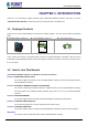
User’s Manual of IMG-120T CHAPTER 1. INTRODUCTION Thank you for purchasing PLANET Industrial 2-port RS422/485 Modbus Gateway, IMG-120T. The term “Industrial Modbus Gateway” mentioned in this user’s manual refers to the IMG-120T. 1.1 Package Contents Open the box of the Industrial Modbus Gateway and carefully unpack it.
User’s Manual of IMG-120T 1.3 Product Description (FRQRPLFDO 6ROXWLRQ IRU ,QGXVWULDO 0RGEXV 7&3 578 $6&,, 1HWZRUN ,QWHJUDWLRQ 3/$1(7 KDV DGGHG WKH ,QGXVWULDO 0RGEXV 7&3 ,3 3URWRFRO WR LWV ,0* 7 ,QGXVWULDO OHYHO SRUW 56 0RGEXV *DWHZD\ DQ LQGXVWULDO PDQDJHPHQW OHYHO SURGXFW WKDW FRPHV ZLWK 6&$'$ +0, V\VWHP DQG RWKHU GDWD DFTXLVLWLRQ V\VWHPV RQ WKH IDFWRU\ IORRU 0RUHRYHU DQ LQGXVWULDO ,7 6103 QHWZRUN FDQ EH XSJUDGHG WR DQ ,QGXVWULDO DXWRPDWLRQ 0RGEXV 7&3 ,3 QHWZRUN ZLWKRXW DQ\ GLIILFXOW\ DQG
User’s Manual of IMG-120T Remote Management The Industrial Modbus Gateway makes the connected industrial Modbus RTU/ASCII equipment become IP-based facilities and is able to connect to the Modbus TCP/IP network via its R422/485 serial interface and 10/100BASE-TX RJ45 Ethernet port. It provides a remote web management and telnet Interface for efficient remote network management.
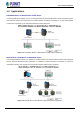
User’s Manual of IMG-120T 1.4 Applications RTU/ASCII Master to Multi Modbus TCP/IP Slaves The Industrial Modbus Gateway can act as a bridge between the industrial RTU/ASCII master equipment and the multi-industrial TCP/IP slave equipment in a Modbus TCP/IP networking environment to control multi-industrial TCP/IP slave equipment via the industrial RTU/ASCII master equipment.
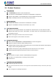
User’s Manual of IMG-120T 1.5 Product Features Serial Interface ■ Two RS422/485 ports with 5-contact terminal block ■ Cost effective for RS422/RS485 to Fast Ethernet 10/100BASE-TX application ■ Supports 4-wire RS422 or 2-wire RS485 with 5-contact terminal block operation ■ 300bps~115200bps baud rate and non-blocking communication Ethernet Interface ■ Complies with IEEE 802.3, IEEE 802.
User’s Manual of IMG-120T 1.
User’s Manual of IMG-120T ASCII Master ASCII Slave Standards Conformance Standards Compliance IEEE 802.310BASE-T standard IEEE 802.3u 100BASE-TX standard IEEE 802.
User’s Manual of IMG-120T CHAPTER 2. HARDWARE INSTALLATION This section describes the hardware features and installation of the Industrial Modbus Gateway’s components on the desktop or shelf. For easier management and control of the Industrial Modbus Gateway, familiarize yourself with its display indicators, and ports. Front panel illustrations in this chapter display the unit LED indicators. Before connecting any network device to the Industrial Serial Converter, please read this chapter completely. 2.
User’s Manual of IMG-120T Figure 2-2 shows the front panel of the Industrial Modbus Gateway. Figure 2-2: Industrial Modbus Gateway Front Panel 2.1.2 LED Indicators ■ LED Definition ■ System LED Color Power Green Function Lights to indicate the system has power. ■ 10/100BASE-TX Interface LED Color LNK/ACT Green Function Lights: To indicate the link through that port is successfully established. To indicate that the IMG-120T is actively sending or receiving data over that Blinks: port.
User’s Manual of IMG-120T LED Color RX1/RX2 Green Function Blinks: To indicate that the IMG-120T is actively receiving data over that port. 2.1.3 2-Contact Terminal Block Pin Define ■ Wiring the Power Inputs: The 2-contact terminal block connector on the top panel of the Industrial Modbus Gateway is used for DC power input and the DC power input range is 9-48V.
User’s Manual of IMG-120T 2.1.5 Hardware DIP Switch for Reset to Default The upper panel of the Industrial Modbus Gateway consists one 4-bit DIP switch for resetting the system to the factory default mode. ■ Resetting to default through hardware DIP switch: 1: Find the hardware DIP switch that is near the RJ45 port of the Industrial Modbus Gateway. 2: Adjust DIP 2 at the “ON” position and DIPs 1, 3, 4 remain at the original position.
User’s Manual of IMG-120T CHAPTER 3. INDUSTRIAL MODBUS GATEWAY MANAGEMENT This chapter describes how to manage the Industrial Modbus Gateway. Sections include: • Overview • -Requirements • Management Methods • PLANET Smart Discovery Utility • PLANET Modbus Gateway Utility 3.1 Overview This chapter gives an overview of the Industrial Modbus Gateway management. The Industrial Modbus Gateway provides a remote IP-based WEB browser/Telnet interface.
User’s Manual of IMG-120T Please refer to the following Chapters 4, 5 and 6 for more details. 3.2 Requirements Ethernet Port Connection • Workstations running Windows XP/2003/Vista/7/8/2008/10, MAC OS X or later, Linux, UNIX, or other platforms are compatible with TCP/IP protocols. • Workstations are installed with Ethernet NIC (Network Interface Card) Network cables -- Use standard network (UTP) cables with RJ45 connectors.
User’s Manual of IMG-120T You can then use your Web browser to list and manage the Industrial Modbus Gateway configuration parameters from one central location. Web Management requires either Microsoft Internet Explorer 8.0 or later, Google Chrome, Safari or Mozilla Firefox 1.5 or later. 3.3.2 Login the Industrial Modbus Gateway Web Interface The following shows how to start up the Web Management of the Industrial Modbus Gateway.
User’s Manual of IMG-120T Figure 3-5: Web Main Screen of Industrial Modbus Gateway For security reason, please change and memorize the new password after this first setup. 1. Only accept command in lowercase letter under web interface. 3.3.3 Remote IP-based Telnet Interface The Industrial Modbus Gateway offers management features that allow users to manage the Industrial Modbus Gateway from anywhere on the network through remote IP-based telnet interface.
User’s Manual of IMG-120T 3.3.4 Login the Industrial Modbus Gateway Telnet Interface The following shows how to start up the Telnet Management of the Industrial Modbus Gateway. Note the Industrial Modbus Gateway is configured through an Ethernet connection. Please make sure the manager PC must be set to the same IP subnet address. For example, the default IP address of the Industrial Modbus Gateway is 192.168.0.100, then the manager PC should be set to 192.168.0.
User’s Manual of IMG-120T 2. Find and deposit the Planet Smart Discovery Utility in administrator PC. 3. Run this utility as the following screen appears. Figure 3-9: Planet Smart Discovery Utility Screen If there are two LAN cards or above in the same administrator PC, choose a different LAN card by using the “Select Adapter” tool. 4. Press the “Refresh” button for the currently connected devices in the discovery list as the screen shows below: Figure 3-10: Planet Smart Discovery Utility Screen 1.
User’s Manual of IMG-120T 2. After the setup is completed, press the “Update Device”, “Update Multi” or “Update All” button to take effect. The functions of the 3 buttons above are shown below: Update Device: Use the current setting on one single device. Update Multi: Use the current setting on multi-devices. Update All: Use the current setting on all the devices in the list. The same functions mentioned above also can be found in the “Option” tool bar. 3.
User’s Manual of IMG-120T Figure 3-11: Planet Modbus Gateway Utility Install Process Screen Figure 3-12: Planet Modbus Gateway Utility Install Process Screen -24-
User’s Manual of IMG-120T Figure 3-13: Planet Modbus Gateway Utility Install Process Screen Figure 3-14: Planet Modbus Gateway Utility Install Process Screen -25-
User’s Manual of IMG-120T Figure 3-15: Planet Modbus Gateway Utility Install Process Screen Figure 3-16: Planet Modbus Gateway Utility Install Process Screen -26-
User’s Manual of IMG-120T Figure 3-17: Planet Modbus Gateway Utility Install Complete Screen 4. Find the PLANET Modbus Gateway UtilityV1.0 icon on the desktop of administrator PC and double-click it as the icon is shown below: 5. After the installation is completed, execute the utility. The screen in Figure 3-18 appears.
User’s Manual of IMG-120T Figure 3-18: Planet Modbus Gateway Utility Main Screen 3.5.2 PLANET Modbus Gateway Utility Menu Bar The Planet Modbus Gateway Utility menu bar has the following options: - System(S) - Tools(Y) Figure 3-19: Planet Modbus Gateway Utility Tool Bar Screen 3.5.2.1 System(S) This function provides Select network adapter and Quit for closing the PLANET Modbus Gateway Utility.
User’s Manual of IMG-120T Figure 3-21: Planet Modbus Gateway Utility Tool Bar System -- Select network adapter Screen Quit This option allows you to press “Quit” for closing the PLANET Modbus Gateway Utility. Figure 3-22: Planet Modbus Gateway Utility Tool Bar System -- Quit Screen 3.5.2.
User’s Manual of IMG-120T Search Device This option allows you to search the connected Industrial Modbus Gateway for further management .
User’s Manual of IMG-120T Figure 3-26: Planet Modbus Gateway Utility Tool Bar -- Set Timing Save Screen Manual Add Device This option allows you to manually set up IP search device and send search unicast packets; there are two ways to manually add the device as shown below: 1: Add "On line Devices" under an existing IP address, click "√" in front of the desired IP address and click on ">" to add IP address; 2: A "Device IP Address" is filled out to manually enter the IP address and click "Add" to add the
User’s Manual of IMG-120T Figure 3-27: Planet Modbus Gateway Utility Tool Bar -- Manual Add Device Screen Batch IP Settings This option allows you to set up IP addresses for a group of devices so as to avoid one-by-one setting, which can save a lot of time. Figure 3-28: Planet Modbus Gateway Utility Tool Bar -- Batch IP Settings Screen The IP address range is 1-254. 3.5.
User’s Manual of IMG-120T -Refresh Interval Figure 3-29: Planet Modbus Gateway Utility Shortcut Menu Bar Screen 3.5.3.1 User Manager : This function provides setting up user name and password for PLANET Modbus Gateway Utility to avoid illegal modification on the Industrial Modbus Gateway. Figure 3-30: Planet Modbus Gateway Utility Shortcut Menu Bar -- User Manager Screen The page includes the following fields: Object Description • New Name The ID of the user. Maximum length: 18 characters.
User’s Manual of IMG-120T 3.5.3.2 Import Network Topology : This function provides the import topology in PLANET Modbus Gateway Utility. Step 1: Click the shortcut icon for the “import Network Topology” and enter search screen of administrator PC. Step 2: Choose a “.BEF” document to be imported. 3.5.3.3 Export Network Topology : This function provides the export topology in PLANET Modbus Gateway Utility and saved as “.BEF” document. For further review, please use the “Import Network Topology” function.
User’s Manual of IMG-120T 3.5.3.9 Batch IP Settings : This option allows you to set up IP addresses for a group of devices so as to avoid one-by-one setting, which can save a lot of time. Figure 3-32: Planet Modbus Gateway Utility Shortcut Menu Bar -- Batch IP Settings Screen The IP address range is 1-254. 3.5.3.10 Batch Monitoring IP Settings : This option allows you to set up Batch Monitoring IP addresses for a group of devices.
User’s Manual of IMG-120T Figure 3-33: Planet Modbus Gateway Utility Shortcut Menu Bar -- Batch Monitoring IP Settings Screen Button : Click to apply changes. 3.5.3.11 Hide Device Tree/Show Device Tree : This option allows you to hide or show the device tree in Industrial Modbus Gateway Utility. 3.5.3.12 Hide Alarm List/Show Alarm List : This option allows you to hide or show the alarm list in Industrial Modbus Gateway Utility. 3.5.3.
User’s Manual of IMG-120T 3.5.4 PLANET Modbus Gateway Utility Device Function The Planet Modbus Gateway Utility provides the following options for Industrial Modbus Gateway device management. - Web Console - Device Name -Network Settings -Reset Factory Settings -Recent Alarm 3.5.4.1 Web Console This function provides Web interface access to PLANET Modbus Gateway. Figure 3-34: Planet Modbus Gateway Utility Device Function -- Web Console Screen 3.5.4.
User’s Manual of IMG-120T Figure 3-35: Planet Modbus Gateway Utility Device Function -- Device Name Screen Button : Click to apply changes. 3.5.4.3 Network Settings This function is to change the IP subnet address of PLANET Modbus Gateway. Figure 3-36: Planet Modbus Gateway Utility Device Function -- Network Settings Screen Button : Click to apply changes. 3.5.4.
User’s Manual of IMG-120T Step 3: Right-click to choose the “Restore Factory Settings”. Figure 3-37: Planet Modbus Gateway Utility Device Function -- Restore Factory Settings Screen Step 4: Click “Yes” when the “Are you sure to restore factory settings” pop window appears. Figure 3-38: Planet Modbus Gateway Utility Device Function -- Restore Factory Settings Screen Step 5: Press “OK” to complete the factory default procedure.
User’s Manual of IMG-120T Figure 3-39: Planet Modbus Gateway Utility Device Function -- Restore Factory Settings Screen Button : Click to apply changes. Step 6: Search the device again and you will see the Industrial Modbus Gateway with default IP address, and username and password: “admin”. Figure 3-40: Planet Modbus Gateway Utility Device Function -- Restore Factory Settings Screen 3.5.4.
User’s Manual of IMG-120T Figure 3-41: Planet Modbus Gateway Utility Device Function -- Recent Alarm Screen -41-
User’s Manual of IMG-120T CHAPTER 4. WEB MANAGEMENT The Industrial Modbus Gateway provides Web interface for management function configuration which makes the Industrial Modbus Gateway operate more effectively. It can be configured through the various web browser tools. A network administrator can manage and monitor the Industrial Modbus Gateway from the local LAN. This section indicates how to configure the Industrial Modbus Gateway to enable its management to function. 4.
User’s Manual of IMG-120T Slave ID: configure Slave ID Map Table parameters. State Monitoring Display the serial port communication traffic counters in transmit and receive. Access Control Configure access control parameters as shown below: Device Security: allow disable or enable Web Console, Telnet Console, Device Search, Firmware Upgrade function. IP Filtering: set up the IP address filtering function. MAC Filtering: set up the MAC address filtering function.
User’s Manual of IMG-120T 4.2 Overview The System Information page provides information for the current device. It helps a network manager to identify the versions and IP Address. The screen in Figure 4-2 appears. Figure 4-2: Overview Screen The page includes the following fields: Basic Settings • Model The model name of Industrial Modbus Gateway. • Hardware Version The current hardware version of Industrial Modbus Gateway. • Module The module information of Industrial Modbus Gateway.
User’s Manual of IMG-120T • MAC Address The MAC address information of Industrial Modbus Gateway.
User’s Manual of IMG-120T 4.3 Network Settings This function allows setting the value for network configuration. The value is DHCP client, IP address, Subnet Mask, or Gateway, DNS. Press the “Submit” button to set the value and the screen in Figure 4-3 appears. Figure 4-3: Network Settings Screen The page includes the following configurable data: Network Settings • Use the following IP Address Choose static IP address for the Industrial Modbus Gateway.
User’s Manual of IMG-120T DNS server address • DNS Server Gateway. DNS is the way that Internet domain names are identified and translated into IP addresses. A domain name is an alphanumeric name, such as planet.com, which is usually easier to remember. Assign the DNS server IP address. IP Report • Server Address Need to report to the top of the host IP. • Server Port When reporting or listening to the port, the default is 4002. • Repeat Time Report IP interval (seconds); the default is 10.
User’s Manual of IMG-120T 4.4 Serial Settings This function provides serial port COM settings and displays the serial port COM information. 4.4.1 COM Settings This function allows setting the value for serial port COM configuration. Press the “Submit” button to set the value and the screen in Figure 4-4 appears. Figure 4-4: Serial Settings -- COM Settings Screen The page includes the following configurable data: Port Setting • Port Display the COM1 information.
User’s Manual of IMG-120T • Parity Bits It is a simple method to check out fault in serial communication; it has 4 types: Even/Odd/Mark/Space. • Flow Control Flow control is determined by product hardware. For some reason, it cannot communicate. When communication is blocked, open the flow control to ease. Flow control allows the data receiving device to notify the data sending device when it is unable to receive the data, so that it can be stopped. It includes XON/XOFF,DTR/DSR, and RTS/CTS.
User’s Manual of IMG-120T The screen in Figure 4-5 appears.
User’s Manual of IMG-120T 4.5 Modbus Settings This function provides Modbus parameters settings and slave ID settings. 4.5.1 Modbus Parameters This function allows setting the value for serial port COM configuration. Press the “Submit” button to set the value and the screen in Figure 4-4 appears. Figure 4-6: Modbus Parameters Screen The page includes the following fields: Modbus Setting This function due to the Modbus from the machine device initialization time is relatively long.
User’s Manual of IMG-120T • Inter-character Timeout (0ms,10-500ms) In a single frame, the time difference is between a single character and the next character. When the value is 0, the default is 3.5T time, which is equal to 3.5 characters. The available range is 10-500ms. The current RTU response with the next RTU request is between the time intervals. The default is 0ms. This feature is to avoid the RTU request from the station equipment.
User’s Manual of IMG-120T setting the ID range and ID offset. Only the channel type in the slave mode of the channel can be set up, including the Slave ASCII, Slave RTU and Slave TCP. Virtual ID + ID Offset = Real ID (Actual ID). This function allows setting the value for slave ID configuration. Press the “Add” and “Submit” buttons to set the value and the screen in Figure 4-7 appears. Figure 4-7: Slave ID Screen The page includes the following fields: Slave ID Map Table Channel No.
User’s Manual of IMG-120T Operate Provide Delete and Modify button. to access the following parameters screen. Press Figure 4-8: Slave ID Parameters Screen The page includes the following fields: Remote IP Address Allow input the remote IP address. TCP Port This parameter is to input the TCP port and available range is 1-65535. Slave ID Start This parameter is to input the start Slave ID and available range is 0-247.
User’s Manual of IMG-120T Figure 4-9: Slave ID Parameters Screen Figure 4-10: Slave ID-RTU Master Screen The IP address of the TCP is 192.168.0.188 (For example, the IP address of the local PC), the TCP port number is 6000, and the virtual ID is 3~4. Offset is 2. RTU Slave Mode This function allows the users to use Modbus TCP master device and Modbus RTU device to achieve communication. The operation mode of the Industrial Modbus Gateway is set to RTU Slave. Step 1: Choose” RTU Slave” in Channel Type.
User’s Manual of IMG-120T Figure 4-11: Slave ID Parameters Screen Figure 4-12: Slave ID-RTU Slave Screen The virtual ID is 3~4. Offset is 2 in Channel No 1. ASCII Master Mode This function allows the users to use Modbus ASCII master device and Modbus TCP device to achieve communication. The operation mode of the Industrial Modbus Gateway is set to ASCII Master. Step 1: Choose “ASCII Master” in Channel Type. Step 2: Press the “Add” button to input the setting parameters.
User’s Manual of IMG-120T Step 3: After setup is completed, press the “Affirm” button to take effect. Figure 4-13: Slave ID Parameters Screen Figure 4-14: Slave ID-ASCII Master Screen The IP address of the TCP is 192.168.0.188 (For example, the IP address of the local PC), the TCP port number is 6000, and the virtual ID is 3~4. Offset is 2. ASCII Slave Mode This function allows the users to use Modbus TCP master device and Modbus ASCII device to achieve communication.
User’s Manual of IMG-120T Step 3: After setup is completed, press the “Affirm” button to take effect. Figure 4-15: Slave ID Parameters Screen Figure 4-16: Slave ID-ASCII Slave Screen The virtual ID is 3~4. Offset is 2 in Channel No 1.
User’s Manual of IMG-120T 4.6 State Monitoring This function provides Industrial Modbus Gateway serial COM port traffic counter in Transmit (TX) and Receive (RX). 4.6.1 COM State The function displays the serial port COM state information like the current traffic counter of serial port as the screen in Figure 4-17 appears. Figure 4-17: State Monitoring -- COM State Screen The page includes the following fields: Port Indicate the port number.
User’s Manual of IMG-120T RTS Indicate the “On” or “Off” status of RTS function. Clear ALL This function allows to clear the current serial COM port traffic counter in Transmit (TX) and Receive (RX). 4.7 Access Control This function provides access control parameters of Industrial Modbus Gateway, including: -Device Security -IP Filtering -MAC Filtering -User Management 4.7.1 Device Security This function allows setting up the device security functions of Industrial Modbus Gateway.
User’s Manual of IMG-120T Device Search This function provides “Disable” or “Enable” the device search function. Firmware Upgrade This function provides “Disable” or “Enable” the firmware upgrade function. Button : Click to apply changes. 4.7.2 IP Filtering This function allows setting up the IP Filtering function of Industrial Modbus Gateway. Press the “Submit” button to apply the setting as the screen in Figure 4-19 appears.
User’s Manual of IMG-120T IP Address This function allows inputting the IP address. Subnet Mask This function allows inputting the Subnet Mask value. Button : Click to apply changes. 4.7.3 MAC Filtering This function allows setting up the MAC Filtering function of Industrial Modbus Gateway. Press the “Submit” button to apply the setting as the screen in Figure 4-20 appears.
User’s Manual of IMG-120T Button : Click to apply changes. 4.7.4 User Management This function allows setting up the user management function of Industrial Modbus Gateway. Press the “Submit” button to apply the setting as the screen in Figure 4-21 appears. Figure 4-21: Access Control -- User Management Screen The page includes the following configurable data: Authentication This function provides “Disable” or “Enable” the authentication function.
User’s Manual of IMG-120T Buttons : Click to edit the username and password. : Click to apply changes. : Click to apply changes. 4.8 System Management This function provides access control parameters of Industrial Modbus Gateway, including: -System Information -System File -Logout & Reboot 4.8.1 System Information This function allows editing the system information of Industrial Modbus Gateway. Press the “Submit” button to apply the setting as the screen in Figure 4-22 appears.
User’s Manual of IMG-120T Description This function provides inputting the description and the available range is 18 letters. Serial Number This function provides inputting the serial number information and the available range is 20 numbers. Contact Information This function provides inputting the contact information and the available range is 20 letters. Button : Click to apply changes. 4.8.
User’s Manual of IMG-120T Configuration Upload Configuration Press the “Choose File” to find the configuration file and press the “Upload” button to start the configuration upload process. Upgrade Firmware from Local PC Update Firmware Press the “Choose File” to find the firmware file and press the “Upgrade” button to start the firmware upgrade process. 4.8.
User’s Manual of IMG-120T CHAPTER 5. COMMAND LINE INTERFACE 5.1 Accessing the CLI When accessing the management interface for the Industrial Modbus Gateway via a remote Telnet connection, the Industrial Modbus Gateway can be managed by entering command keywords and parameters at the prompt. Using the Industrial Modbus Gateway’s command line interface (CLI) is very similar to entering commands on an UNIX system.
User’s Manual of IMG-120T Figure 5-2: Telnet Main Screen of Industrial Modbus Gateway 1. For security reason, please change and memorize the new password after this first setup. 2. Only accept command in lowercase letter under web interface.
User’s Manual of IMG-120T CHAPTER 6. COMMAND LINE MODE The CLI groups all the commands in appropriate modes according to the nature of the command. A sample of the CLI command modes are described below. Each of the command modes supports specific software commands. After logging in and accessing the Industrial Modbus Gateway Telnet interface, please enter “?” or “help” under Industrial Modbus Gateway Telnet interface where it displays a list of the available commands and descriptions of the commands.
User’s Manual of IMG-120T Serial This command will access serial setup menu. Security This command will access security setup menu. Manage This command will access system management menu. Information This command will access system information setup menu. Modbus This command will access Modbus setup menu. Command lines online help Description: Command lines port provides the following online help Total help Partial help Syntax: Total help Type in To get all commands and their description.
User’s Manual of IMG-120T Modbus
--Enter Modbus manage menu Type in former letters of some key word of the command, press key. If the letters are unique, it can show the completed key word. Example: ModbusGateway(Device)# inf + ModbusGateway(Device)# information History command Description: Command lines port can provide the function similar to Dos key. It automatically saves command lines that users type in, and users can use these history commands.User’s Manual of IMG-120T APPENDIX A A.1 Device‘s RJ45 Pin Assignments ■ 10/100Mbps, 10/100BASE-TX Contact 1 2 3 6 4, 5, 7, 8 MDI 1 (TX +) 2 (TX -) 3 (RX +) 6 (RX -) Not used MDI-X 3 6 1 2 Not used Implicit implementation of the crossover function within a twisted-pair cable, or at a wiring panel, while not expressly forbidden, is beyond the scope of this standard. A.2 RJ45 cable pin assignment 6 32 1 6 321 6 3 21 There are 8 wires on a standard UTP/STP cable and each wire is color-coded.
User’s Manual of IMG-120T 4 = Blue 5 = White / Blue 6 = Green 7 = White / Brown 8 = Brown SIDE 2 4 = Blue 5 = White / Blue 6 = Orange 7 = White / Brown 8 = Brown Figure A-1: Straight-through and Crossover Cable Please make sure your connected cables are with same pin assignment and color as the above diagram before deploying the cables into your network.