
User Manual
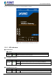
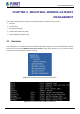
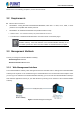
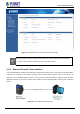
Table Of Contents
- Chapter 1. INTRODUCTION
- Chapter 2. HARDWARE INSTALLATION
- Chapter 3. INDUSTRIAL MODBUS GATEWAY MANAGEMENT
- Chapter 4. WEB MANAGEMENT
- Chapter 5. COMMAND LINE INTERFACE
- Chapter 6. COMMAND LINE MODE
- APPENDIX A

User’s Manual of IMG-120T
-14-
Figure 2-2 shows the front panel of the Industrial Modbus Gateway.
Figure 2-2: Industrial Modbus Gateway Front Panel
2.1.2 LED Indicators
■ LED Definition
■ System
LED Color Function
Power
Green
Lights to indicate the system has power.
■ 10/100BASE-TX Interface
LED Color Function
LNK/ACT Green
Lights
: To indicate the link through that port is successfully established.
Blinks:
To indicate that the IMG-120T is actively sending or receiving data over that
port.
■ RS422/RS485 Serial Port
LED Color Function
TX1/TX2 Green Blinks:
To indicate that the IMG-120T is actively transmitting data over that port.