
User Manual

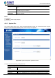

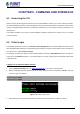
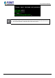
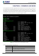
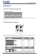
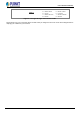
Table Of Contents
- Chapter 1. INTRODUCTION
- Chapter 2. HARDWARE INSTALLATION
- Chapter 3. INDUSTRIAL MODBUS GATEWAY MANAGEMENT
- Chapter 4. WEB MANAGEMENT
- Chapter 5. COMMAND LINE INTERFACE
- Chapter 6. COMMAND LINE MODE
- APPENDIX A

User’s Manual of IMG-120T
-72-
APPENDIX A
A.1 Device‘s RJ45 Pin Assignments
■ 10/100Mbps, 10/100BASE-TX
Contact
MDI
MDI-X
1
1 (TX +)
3
2
2 (TX -)
6
3
3 (RX +)
1
6
6 (RX -)
2
4, 5, 7, 8
Not used
Not used
Implicit implementation of the crossover function within a twisted-pair cable, or at a wiring panel, while not
expressly forbidden, is beyond the scope of this standard.
A.2 RJ45 cable pin assignment
2
1
3
6
1
2
3
6
2
1
3
6
There are 8 wires on a standard UTP/STP cable and each wire is color-coded. The following shows the pin
allocation and color of straight cable and crossover cable connection:
Straight Cable SIDE 1 SIDE 2
1 2
3 4 5 6 7 8
1 2
3 4 5 6 7 8
SIDE 1
1 = White / Orange
2 = Orange
3 = White / Green
4 = Blue
5 = White / Blue
6 = Green
7 = White / Brown
8 = Brown
1 = White / Orange
2 = Orange
3 = White / Green
4 = Blue
5 = White / Blue
6 = Green
7 = White / Brown
8 = Brown
SIDE 2
Straight Cable SIDE 1 SIDE 2
1 2 3 4 5 6 7
8
SIDE 1
1 = White / Orange
2 = Orange
3 = White / Green
1 = White / Orange
2 = Green
3 = White / Orange