5/8-Port 10/100/1000Mbps Industrial Gigabit Ethernet Switch IGS-501 / IGS-801 / IGS-501T / IGS-801T User's Manual
Trademarks Copyright © PLANET Technology Corp. 2009. Contents subject to revision without prior notice. PLANET is a registered trademark of PLANET Technology Corp. All other trademarks belong to their respective owners. Disclaimer PLANET Technology does not warrant that the hardware will work properly in all environments and applications, and makes no warranty and representation, either implied or expressed, with respect to the quality, performance, merchantability, or fitness for a particular purpose.
communications. Operation of this equipment in a residential area is likely to cause harmful interference in which case the user will be required to correct the interference at his own expense. CE Mark Warning This is a Class A product. In a domestic environment, this product may cause radio interference, in which case the user may be required to take adequate measures.
Table Of Contents 1. INTRODUCTION......................................................................... 6 1.1 Package Contents................................................................ 6 1.2 How to Use This Manual ..................................................... 6 1.3 Product Features.................................................................. 7 1.4 Product Specifications.......................................................... 8 2. INSTALLATION..........................................
4.5 Auto-Negotiation.................................................................21 5. TROUBLESHOOTING..................................................................22 APPENDIX A: NETWORKING CONNECTION........................................23 A.1 Switch’s RJ-45 Pin Assignments............................................23 A.2 RJ-45 cable Pin Assignments................................................
1. INTRODUCTION 1.1 Package Contents Check the contents of your package for following parts: l Industrial Gigabit Ethernet Switch x 1 l User's manual x 1 l DIN rail kit x 1 l Wall mount kit x 1 If any of these are missing or damaged, please contact your dealer immediately, if possible, retain the carton including the original packing material, and use them against to repack the product in case there is a need to return it to us for repair. 1.
1.3 Product Features Physical Port l 5-Port 10/100/1000Base-T RJ-45 with auto MDI/MDI-X function (IGS501 / IGS-501T) l 8-Port 10/100/1000Base-T RJ-45 with auto MDI/MDI-X function (IGS801 / IGS-801T) Layer 2 Features l Complies with IEEE 802.3 10Base-T, IEEE 802.3u 100Base-TX, IEEE 802.
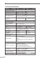
1.4 Product Specifications Model IGS-501 IGS-801 Hardware Specification 10/100/1000Base-T Ports 5 8 Dimensions (W x D x H) 135mm x 87mm x 32mm Weight 455g Power Requirement 12~48 VDC, Redundant power with polarity reverse protection function 473g Power Consumption / Dissipation 11.9 Watts / 40BTU Installation DIN rail kit and wall mount ear 13.
Model IGS-501T IGS-801T Hardware Specification 10/100/1000Base-T Ports 5 8 Dimensions (W x D x H) 135mm x 87mm x 32mm Weight 455g Power Requirement 12~48 VDC, Redundant power with polarity reverse protection function 473g Power Consumption / Dissipation 11.9 Watts / 40BTU Installation DIN rail kit and wall mount ear 13.
2. INSTALLATION This section describes the functionalities of the Industrial Gigabit Ethernet Switch’s components and guides how to install it on the desktop. Basic knowledge of networking is assumed. Please read this chapter completely before continuing. In the following section, the term “Industrial Gigabit Ethernet Switch” means the IGT-501 / IGT-801 / IGT-501T / IGT-801T. 2.
2.1.1 Product Overview The PLANET Industrial Gigabit Ethernet Switch with 5/8 RJ-45 10/100/1000Mbps ports for high-speed network connectivity. The Industrial Gigabit Ethernet Switch can also automatically identify and determine the correct transmission speed and half / full duplex mode of the attached devices with its 5/8 ports. The Gigabit port with 9K jumbo frame feature supported, can handle extremely large amounts of data transmission in a secure topology linking to a backbone or highpower servers.
Figure 2-3 IGS-501T front panel Figure 2-4 IGS-801T front panel 2.1.3 LED Indicators LED Color Function P1 Green Lit: indicate the power 1 has power. P2 Green Lit: indicate the power 2 has power. FAULT Green Lit: indicate the either power 1 or power 2 has no power. 1000 Green Lit: indicate the Switch is successfully connecting to the network at 1000Mbps. Off: indicate that the Switch is successfully connecting to the network at 10Mbps or 100Mbps.
2.1.4 Switch Upper Panel The upper panel of the Industrial Gigabit Ethernet Switch consist one terminal block connector within two DC power inputs. Figure 2-5 shows the upper panel of the switch. Figure 2-5 shows upper panel of Industrial Gigabit Ethernet Switch. Figure 2-5 Industrial Gigabit Ethernet Switch upper Panel. 2.1.5 Wiring the Power Inputs The 6-contact terminal block connector on the top panel of Industrial Gigabit Ethernet Switch is used for two DC redundant powers input.
2. Tighten the wire-clamp screws for preventing the wires from loosing. 1 2 Power 1 - Note 3 4 Fault + 5 6 Power 2 - + The wire gauge for the terminal block should be in the range between 12 ~ 24 AWG. 2.1.6 Wiring the Fault Alarm Contact The fault alarm contacts are in the middle of the terminal block connector as the picture shows below.
2.2 Mounting Installation This section describes how to install the Industrial Gigabit Ethernet Switch and make connections to it. Please read the following topics and perform the procedures in the order being presented. 2.2.1 DIN-Rail mounting The DIN-Rail is screwed on the Industrial Gigabit Ethernet Switch when out of factory.
Step 1: screw the DIN-Rail on the Industrial Gigabit Ethernet Switch. Step 2: Lightly press the button of DIN-Rail into the track. Step 3: Check the DIN-Rail is tightly on the track. Step 4: Please refer to following procedures to remove the Industrial Gigabit Ethernet Switch from the track.
Step 5: Lightly press the button of DIN-Rail for remove it from the track. 2.2.2 Wall Mount Plate Mounting To install the Industrial Gigabit Ethernet Switch on the wall, please follows the instructions described below. Step 1: Remove the DIN-Rail from the Industrial Gigabit Ethernet Switch; loose the screws to remove the DIN-Rail. Step 2: Place the wall mount plate on the rear panel of the Industrial Gigabit Ethernet Switch.
3. APPLICAITON In this paragraph, we will describe how to install Industrial Gigabit Ethernet Switch and the installation points for the attention.
Step 3: To hang the Industrial Gigabit Ethernet Switch on the DINRail track or wall, please refer to the Mounting Installation section. Step 4: Power on the Industrial Gigabit Ethernet Switch. (Please refer to the Wiring the Power Inputs section for power input) The power LED on the Industrial Gigabit Ethernet Switch will light up. Please refer to the LED Indicators section for meaning of LED lights. Step 5: Prepare the twisted-pair, straight through Category 5 cable for Ethernet connection.
4. SWITCH OPERATION 4.1 Address Table The Industrial Gigabit Ethernet Switch is implemented with an address table. This address table composed of many entries. Each entry is used to store the address information of some node in network, including MAC address, port no, etc. This information comes from the learning process of Industrial Gigabit Ethernet Switch. 4.2 Learning When one packet comes in from any port. The Industrial Gigabit Ethernet Switch will record the source address, port no.
4.4 Store-and-Forward Store-and-Forward is one type of packet-forwarding techniques. A Store-and Forward Industrial Gigabit Ethernet Switch stores the incoming frame in an internal buffer, do the complete error checking before transmission. Therefore, no error packets occurrence, it is the best choice when a network needs efficiency and stability.
5. TROUBLESHOOTING This chapter contains information to help you solve issues. If the Industrial Gigabit Ethernet Switch is not functioning properly, make sure the Industrial Gigabit Ethernet Switch was set up according to instructions in this manual. The per port LED is not lit Solution: Check the cable connection of the Industrial Gigabit Ethernet Switch. Performance is bad Solution: Check the speed duplex mode of the partner device.
APPENDIX A: NETWORKING CONNECTION A.
A.2 RJ-45 cable Pin Assignments The standard RJ-45 receptacle/connector There are 8 wires on a standard UTP/STP cable and each wire is colorcoded.