
User Manual

8
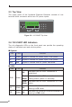
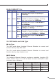
2.3 Top View
The upper panel of the Industrial Ethernet Extender consists of one
terminal block connector within two DC power inputs.
Input
DC12~48V, AC 24V
V1+ V1- V2+ V2-
PWR1
PWR2Fault
1A@24V
1 2 3 4 5 6
Figure 2-3: IVC-234GT Top View
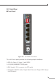
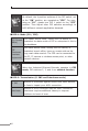
2.4 IVC-234GT LED Indicators
The rich diagnostic LEDs on the front panel can provide the operating
status of individual port and whole system.
System
LED Color Function
P1 Green Lights to indicate DC power input 1 has power.
P2 Green Lights to indicate DC power input 2 has power.
Fault Red Lights to indicate that DC power has failed.
VDSL
LED Color Function
VDSL Green
Lit
Indicates that the VDSL connection is
established.
Fast
Blink
Indicates that the VDSL connection is in
training status (about 15 seconds).
Slow
Blink
Indicates that the VDSL connection is in idle
status.
CO Green Lit
Indicates the Industrial Ethernet Extender is
running in CO mode.
CPE Green Lit
Indicates the Industrial Ethernet Extender is
running in CPE mode.