LoRa Node Controller LN501 and LN1152 LoRa Node Controller LN501 and LN1152 -1-
LoRa Node Controller LN501 and LN1152 Copyright Copyright (C) 2022 PLANET Technology Corp. All rights reserved. The products and programs described in this User’s Manual are licensed products of PLANET Technology, This User’s Manual contains proprietary information protected by copyright, and this User’s Manual and all accompanying hardware, software, and documentation are copyrighted.
LoRa Node Controller LN501 and LN1152 – Increase the separation between the equipment and receiver. – Connect the equipment into an outlet on a circuit different from that to which the receiver is connected. – Consult the dealer or an experienced radio/TV technician for help. CE mark Warning The is a class A device, In a domestic environment, this product may cause radio interference, in which case the user may be required to take adequate measures.
LoRa Node Controller LN501 and LN1152 Table of Contents Chapter 1. Product Introduction............................................................................................. 5 1.1 Package Contents ...................................................................................................... 6 1.2 Overview .................................................................................................................... 7 1.3 Features ..................................................
LoRa Node Controller LN501 and LN1152 Chapter 1. Product Introduction Thank you for purchasing PLANET LoRa Node Controller, LN series. The descriptions of these models are as follows: LN501 Outdoor IP67 LoRa Node Controller with Solar Panel LN1152 Indoor IP30 LoRa Node Controller “LoRa Node” mentioned in the manual refers to the above models.
LoRa Node Controller LN501 and LN1152 1.
LoRa Node Controller LN501 and LN1152 1.2 Overview Feature-rich Sensor Hub for Connecting Sensors PLANET LN501 and LN1152 are LoRa node controllers used for data acquisition from multiple sensors. They contain different I/O interfaces such as analog inputs, digital inputs, digital outputs, serial ports and so on to simplify the deployment and replacement of LoRaWAN networks. LN501: It can be easily and quickly configured by NFC or wired USB port.
LoRa Node Controller LN501 and LN1152 1.
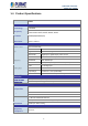
LoRa Node Controller LN501 and LN1152 1.4 Product Specifications Product LN501 Wireless Transmission Technology Frequency LoRaWAN LN501-868M: IN865, EU868, RU864 LN501-915M: US915, AU915, KR920, AS923 Tx Power 16dBm(868)/20dBm(915) Sensitivity -137dBm @300bps Work Mode Class A, Class C Data Interfaces Interface Type IO Serial Port Analog Input Power Output M12 A-Coded Male Ports 2 × GPIO Logical Level Low: 0~0.9V, High: 2.5~3.
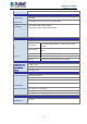
LoRa Node Controller LN501 and LN1152 Product LN1152 Wireless Transmission Technology LoRaWAN Antenna × 50 Ω SMA Connectors (Center Pin: SMA Female) Connector Frequency LN1152-868: IN865, EU868, RU864 LN1152-915: US915, AU915, KR920, AS923 Tx Power 16dBm(868)/20dBm(915) Sensitivity -147dBm @300bps Work Mode OTAA/ABP Class C Data Interfaces Interface Type 3.
LoRa Node Controller LN501 and LN1152 Chapter 2. Hardware Introduction 2.
LoRa Node Controller LN501 and LN1152 Power Button: Function Action LED Indication Turn On Press and hold the button for more than 3s. Off → On Turn Off Press and hold the button for more than 3s. On → Off Reset Press and hold the button for more than 10s. Blinks. Check On/Off Light On: Device is on. Quickly press the power button. Status Light Off: Device is off. Data Interface: Data Interface 1 Pin Description 1 5V/9V/12V OUT (Switchable) 2 3.
LoRa Node Controller LN501 and LN1152 LN1152 PIN Definition Description 1 GND Ground 2 VIN 5-24 V DC 3 RXD 4 TXD 5 GND 6 A 7 B 8 IN 9 IN_COM 10 OUT_COM 11 OUT_NC 12 OUT_NO RS232 RS485 DI DO LED Definition: LED Indication System Status Description Static System Start-up On for 500 ms, off for 500 ms The system is running properly. System Status The system is not connected to On for 200 ms, off for 200 ms server.
LoRa Node Controller LN501 and LN1152 2.2 Hardware Installation Refer to the illustration and follow the simple steps below to quickly install your LoRa Node. 2.2.1 LoRa Antenna Installation (LN1152) Step 1: Rotate the antenna into the antenna connector accordingly. Step 2: The external LoRa antenna should be positioned vertically for a good signal. 2.2.2 Wall Mounting LN501 Make sure you have a wall mounting bracket, bracket mounting screws, wall plugs, wall mounting screws and other required tools.
LoRa Node Controller LN501 and LN1152 LN1152 Step 1: Align the LN1152 device horizontally to the desired position on the wall and use a marker pen to mark two mounting holes on the wall. Step 2: Drill the two holes marked previously on the wall by using your drill with a 6 mm drill bit. Step 3: Mount the device to the wall by tightly screwing the wall mounting screws (M3 * 20) into the device mounting holes.
LoRa Node Controller LN501 and LN1152 2.2.
LoRa Node Controller LN501 and LN1152 LN1152 series supports 5-24 V DC power supply. You can use other supplies or power adapter to power on the device. For industrial applications, it’s suggested not to release the metal case and use an independent power supply.
LoRa Node Controller LN501 and LN1152 Chapter 3. Preparation Before accessing the LoRa node controllers, user has to install utility tool for operation. 3.1 Requirements • Workstations running Windows 10/XP/2003/Vista/7/8/2008. • Type C USB cable for LN501 • Micro USB cable for LN1152 3.2 Managing LoRa Node 1. Download ToolBox software from Planet web site. 2. https://www.planet.com.tw/en/support/downloads?&method=keyword&keyword=LN501&view=6#list 3.
LoRa Node Controller LN501 and LN1152 Chapter 4. Operations Management This chapter provides operations details of the LoRa node controller. 4.1 Managing LoRa Node 5. Download ToolBox software from Planet web site. 6. https://www.planet.com.tw/en/support/downloads?&method=keyword&keyword=LN501&view=6#list 7. Power on the LoRa Node device and then connect it to computer via micro USB port. 8. Open the ToolBox and select “Type” and then "General", and then click password to log in ToolBox.
LoRa Node Controller LN501 and LN1152 9. After logging in the ToolBox, you can click “Power On” or “Power Off” to turn on/off device and change other settings.
LoRa Node Controller LN501 and LN1152 4.2 LoRaWAN setting LoRaWAN setting is used for configuring the transmission parameters in LoRaWAN ® network. Basic LoRaWAN Settings: Go to “LoRaWAN -> Basic” of ToolBox software to configure join type, App EUI, App Key and other information. You can also keep all settings by default. Object Description Device EUI Unique ID of the device which can also be found on the label. App EUI Default App EUI is 24E124C0002A0001.
LoRa Node Controller LN501 and LN1152 5572404C696E6B4C6F52613230313823. Device Address DevAddr for ABP mode, default is the 5th to 12th digits of SN. Network Session Nwkskey for ABP mode, default is Key 5572404C696E6B4C6F52613230313823. Application Appskey for ABP mode, default is Session Key 5572404C696E6B4C6F52613230313823. Spread Factor If ADR is disabled, the device will send data via this spread factor.
LoRa Node Controller LN501 and LN1152 If frequency is one of AU915/US915, you can enter the index of the channel that you want to enable in the input box, making them separate by commas.
LoRa Node Controller LN501 and LN1152 4.3 Interface setting LN501 and LN1152 support data collection by multiple interfaces including GPIOs, analog inputs and serial ports. Besides, they can also power the terminal devices by power output interfaces. Basic settings are as follows: Go to “General -> Basic” of ToolBox software to change the reporting interval. Object Reporting Interval Description Reporting interval of transmitting data to network server. Default: 20 mins, Range: 1-1080 mins.
LoRa Node Controller LN501 and LN1152 4.3.1 RS485 Settings 1. Connect RS485 device to RS485 port on interface 2. If you need LN501 to power the RS485 device, please connect the power cable of RS485 device to 5V/9V/12V power output on interface 2. 2. Go to “General -> Serial” of ToolBox software to enable RS485 and configure serial port settings. Serial port settings should be the same as RS485 terminal devices.
LoRa Node Controller LN501 and LN1152 Execution Interval The execution interval between Modbus commands. Max. Response Time The maximum response time that the LN501 waits for the reply to the command. If it does not get a response after the maximum response time, it is determined that the command has timed out. Max. Retry Time Set the maximum retry times after device fails to read data from RS485 terminal devices.
LoRa Node Controller LN501 and LN1152 Example: If you configure it as the following picture, LN501 will send Modbus read command to terminal device regularly: 01 03 00 00 00 01 84 0A 4. For ToolBox software, click “Fetch” to check if LN501 can read correct data from terminal devices. You can also click “Fetch” on the top of list to fetch all channel data. Please do not click “Fetch” frequently since response time to reply is different for every terminal device.
LoRa Node Controller LN501 and LN1152 4.3.2 RS232 Settings 1. Connect RS232 device to RS232 port on interface 2. If you need LN501 to power the RS232 device, connect the power cable of RS232 device to 5V/9V/12V power output on interface 1. 2. Go to “General -> Serial” of ToolBox software to enable RS232 and configure serial port settings. Serial port settings should be the same as RS232 terminal devices.
LoRa Node Controller LN501 and LN1152 4.3.3 GPIO Settings 1. Connect devices to GPIO ports on interface 2. 2. Go to “General -> GPIO” of ToolBox software to enable GPIO port. 3. Select GPIO type according to your requirements. Digital Input: detect high or low status of devices Digital Output: send voltage signal to trigger devices Counter: pulse counter.
LoRa Node Controller LN501 and LN1152 Digital Input: Select initial status of digital input. If pull up is selected, falling edge will be triggered; if pull down is selected, rising edge will be triggered. After selection, click “Fetch” to check current status of digital input. Digital Output: Click “Switch” to check if LN501 can trigger devices by digital output or click “Fetch” to check the current status of digital output.
LoRa Node Controller LN501 and LN1152 Object Digital Input Description Initial status of counter. Pull Down: Increase 1 when detecting rising edge Pull Up/None: Increase 1 when detecting falling edge Digital Filter It’s recommended to enable when pulse period is greater than 250 us. Keep Last Value When Power Keep the counted values when the device powers off. Off Start/Stop Make the device start/stop counting. Note: LN501 will send non-changeable counting values if you do not click“Start”.
LoRa Node Controller LN501 and LN1152 3. Select analog input type according to analog device type. Make sure DIP switch has changed before changing “Analog Input Signal Type” to 0-10V. 4. Enable “Interface 1 (Pin 1) 5V/9V/12V” and configure “Power Output Time Before Collect”, LN501 will power the analog devices for a period of time before collecting data. When you use power output to power analog devices, it only supplies power when reporting interval is coming.
LoRa Node Controller LN501 and LN1152 4.4 Maintenance 4.4.1 Upgrade Go to “Maintenance -> Upgrade” of ToolBox software, click “Browse” to import firmware and upgrade the device. You can also click “Up to Date” to search for the latest firmware of the device and upgrade. 4.4.2 Backup LN501 devices support configuration backup for easy and quick device configuration in bulk. Backup is allowed only for devices with the same model and LoRa frequency band.
LoRa Node Controller LN501 and LN1152 4.4.3 Reset to Factory Default Please select one of following methods to reset device: Hardware: Open the case of LN501 and hold on power button for more than 10s. ToolBox Software: Go to “Maintenance -> Backup and Reset” to click “Reset”.